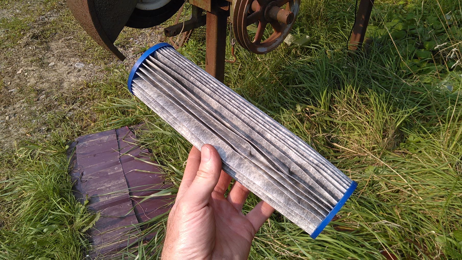
I think your right. If I take my glasses off and take a really close look I think I can see something like micro fiberglass. Must not be paper. I guess I can scrap the blue paper filter idea.
5 Likes
I wonder if anyone is using the kind of filters we used to use when processing maple syrup.
We used an orlon bag filter, with a “paper” pre-tilter inside it.
You can see them by googling:
“maple syrup filters”
I seem to remember that this filter pair made up about a 50 micron filter system. I’m not sure that it would work for hot soot, but they sure worked well for syrup.
If you look into this system, you will see that the sellers tell you that you can wash the pre-filters 2 or 3 times before discarding them. But we washed them over and over, for years.
Pete Stanaitis
5 Likes
Amazon has tons of microfiber cloth to choose from.
- - - - -
Then there is the synthetic filter cloth industry. This is a China company but the information should be close.
http://www.filtercloths.org/filter-cloth/polypropylene-felt-filter-cloth.html
1 Like
I too have thought very long and hard about cyclones, a baghouse and reheating the gas for paper filtering. Patrick Johnson’s work with this process and coupling it up to the WK is very inspiring. I totally respect Vesa’s and Max’s knowledge and proven experience with these systems. SteveU blesses both wet and dry filtering and explains the whys and how’s of it all…
My personal conclusion was, for me, it would be worth all that effort IF I didn’t have a Dakota. I will use these hot filtering systems on other engines that I have, like my carbonated tractors, a great solution to keep the soot out
Besides…all the fun of lighting up the intake on the Dakota would be lost!
Bryan
8 Likes
Ha! Too air choking smoky to do much “physical”. School’s early released 2-hour so the kido’s can go home and hopefully get inside into HEPA filter whole-house systems. AND . . . I just happened to have the right candy bar in-pocket with the right on-net game-playing kid to buy his library-access hour.
So . . .
On the modern open cell foam block blowing condensate soot bubbles that was a MaxG posted up experienced. Not me. I’ve personally only used on-site generated organics, never washed, replenished/replaced out to local property biodegrade enrich.
On this Pegasus Unit topic I did search out and pay dearly for an old original archived book companion Plan-Set. These were sold as an accessory to the book. Book and plan set advertised in the back of popular magazines.
Book has the normal copyright restriction printed in it. The sequence I believe is that the book rights were acquired by Dr Tom Reed for his use in his bio-mass gasification books store. And years later he turned this over to Dr Paul Anderson. Who public domain released it out as a downloadable pdf.
This five sheet of 24"x18" Plan set was not part of this rights transfer.
Every single sheet is big circled C copyrighted and imprinted boldly, “Reproduction Whole or in Part is Strictly Forbidden.”
This plan set was for an individual to build one “Pegasus 125 W For Wood Fuel”.
All copyright author do allow partial quoting and descriptions for promotional and review needs.
So . . .
125 W would mean 123 kW/mechanical powering engines. Page 126 Conversion factor makes this ~93 engine horsepower.
A 1960’s Checker sedan would have had an overhead valve converted I-6 Continental engine, or a Chevrolet small block V-8 engine.
Plan Set sheet 1 says this very Inbert copy unit was for:
“This design is suitable for a medium sized car 1500 to 3000cc” (engines). (92 to 183 CID.)
This very Inbert clone is the cones/tubes formed double throat version. This means it has an oxidization to reduction catch bowl area.
This plan set used the five jet with four air tube to four of these system coming from a common “social” (MaxG) air-inlet box area. Social because it is doing many things at once; balanced, and well.
More of their first sheet plan set descriptions and operating/troubleshooting quotes.
“The enclosed design is easy and simple to build. It will be obvious to the experienced engineer or designer that most of the dimensions are not critical, E.G. plate thicknesses, cleaning out sizes and so forth. judicious substitutions or the use of salvage parts is quite permissible. What IS important is to avoid undue friction in the gas passages by using piping that is too small.
Gas temperature should ideally be near 20 degrees centigrade (68 degrees Fahrenheit) when the gas reaches the engine. Hense a good cooler will improve performance.
Those who enjoy more elaborate technical perfection will find numerous ideals in “The Pegasus Unit” to allow sophisticated refinements.”
OK Their plan set cooler? Sheet 5 of 5
14 element flat vertical tube assembly 25" high including the square cross section upper and lower tanks. Lower tank
airtight" divided across the center. Seven tubes flow UP across top tank then seven tubes flow down. Tubes made up of “14 cooling elements of 16 or 18 gauge steel, 5/8” x 4 1/2" cross section placed 1 1/8" on center, with the two center elements placed 2" O.C."
Unspecified gas-in to the one side of the lower tank. Opposite lower tank side specified to be 5" gas tube out. This out to the cyclone can assembly.
“place two drain cocks in the lower section.” One for each tank side.
This cyclone is very different from any I’ve seem.
Ha! Out of time. Certainly out of brain-concentration. I type slowly.
Tomorrow the cyclone internal details if there is an interest.
S.U.
5 Likes
That one must have the drum like cyclone. The cone is inside the drum like housing. I think it was on a taxi. I got the plans from Tom Reed. Might still have them some where.
1 Like
Yes, interested in cyclone. Recently came across a separator called a Thein plate separator that would take less space than a comparable cone type. TomC
Yes. Yes.
I’m back. I’ve edit corrected my post above. Great apologies to those who English second language. I run out of brain in the afternoon anymore.
JeffD is correct: a cone-in-a-can.
Tom C I do not know a Thain-plate separator. One I will have to look up.
This Plan Set cyclone is specified to be made up, “Fabricate from 18 gauge steel”
A round can with flat ends 16" high by 12" diameter. The internal cone is gas tight to be welded inverted to the top can plate. It is speficifed to be 10" top diameter by 3 1/2 bottom OPEN end diameter. Plan calls for, “Use 2 1/2” light pipe (conduit) Inlet pipe to be tangentially to the cyclone" Illistrates this inlet to be welded 2" center down, at a 90 degrees from the long axis, from the top out edge of the can at (of course) flow spin inducing angle.
A sheet 1 note says that ALL gas piping tubing will be 2 1/2" unless other wise specified. So the very Imbert “stick up in the air” cooler piping inlet would have been 2 1/2"
It is the flow pattered within this assebly that I’ve never seen
gas-in induced to spin-flow down around the OUTSIDE of the cone first. Then lower 3 1/2" open end suck UP spinning? Exits out a 2 1/2" pipe in the top center.
Whole assembly specified to have lower outer edge 4" pipe nipple and cap clean-out centered 3" up from the bottom edge. The lower flat bottom specified to have a , “Place draincock where convenient”
Please under stand that I am not putting any of this up as better-idea’s, or idealism’s.
I am a dedicated statioanry-for-power guy.
No need for me to build this books Figure 52 super compact all integrated system.
And for many other reasons I would not even build up this very-true Imbert clone copy system.
Amazinf though this pulished out “15th Aug. 1974” book and plan set.
Amazing it was priced so cheaply then. Advertised in the classifies sections of Mechanical Illustrated and other USofA widely available magazines.
From exslave-labor/needs-must WWII era western Eropean user of all of the wood, charcoal, and fossile coal system donew by DR Tom reed and others the Imbert system was admired for the ease of use. Ease of maintenance. ONLY downside was they needed reliably pre-dryed down,15% or less moisture fuel woods.
Sheet #1 iuse instruction says fuel wood chunks to be,
“Use good ,air dried wood in sizes one-by-two-by-three inches, approximately.”
Thgis sytem would whup-ass over the 10 year later broadcast out Mother-Earth-News too-many tubed, too many gastight welds, system. Really performance wup-ass over the F.E.M.A crappola tar-maker.
Why was this Pesasus Plans Set system overlooked and ignored?
Social dynamics. Not-invneted-by-me. I’m a modern smarty. Of course I can come up with a better way. Pay-for-fo-a plan?! I’ll just do it all myself.
Same as today, eh?
3 Likes
Easy to answer for me. Never knew it existed until the last go around interest in gas-works-for-me (GWFM). I had no problem paying for MEN plans, they were my only mentors - - God help me ! ! In MEN defense, my mistake was putting it on the back of my only vehicle. It should of been on a trailer or should I call it training wheels.
3 Likes
Hi. I am back.
I’d thought that I’d come to know the history, evolution and 20 years of make-it simpler, more practical to manufacture and use late 1940’s Imbert fuel-wood systems.
Then the Sheet #1 First Start Up instructions showed me I had completely missed one important system intended design compromise: this is neither a all-gas-flow-through-the-grate system. And not a gas-flow-through&up-over-the -grate-bypass system.
Imbert: the grate just holds up the charcoal stack. As needed, minor grate wiggled to gravity-fall sift out accumulated ash from the char stack. ALL gas flows are above the grate trough an inverted V-U flow of extended distanced wrapped char stack!
“First Startingup - - - Fill charcoal through the stack cover (hopper-lid) to a level about four inches above the air holes in the hearth section. Fill charcoal through the upper cleanout and distribute well in the lower part of the housing to the level of the middle of the upper cleanout hole. Now fill wood through the stack cover (hopper-lid). Check gasket and lubricate with grphite before the stack cover is closed. Check that all cocks and valves are closed. Ignite with an alcohol soaked rag through the air intake.”
Net loaded up videos shows these all have full system starting up effective suction blowers. One somewhat fuzzy net video of a 1940’s Imbert sales presentation show well the internal guts with the perimeter ledge mounted flat plate, many holes punched grate. It can only be a few MM back and forth wiggled by the air-tight lock down manual grate shaker.
Now the factory two big upper clean-out/inspection ports make sense.
Now this Plan Sets five seems-too large 5/8" air jets make sense.
Now this Plan sets seems-too-big 5" to-reduction hearth opening makes sense.
System flow is actually being restricted/controlled with gas flowing 2X the apparent height from the inside the hourglass reduction char, to down-over and up through the char stack outside the hourglass.
And the full double walled Imbert housing long up-flow gas is dropping any chars/large chunks back down to help keep the outside the hourglass char bed replenished.
Smart is simple. Practical-use effective is always evolved simple-smart. Mauser 98, Glock 17, Chevy small block, Delco 10 SI, Delco 10 MT, loose fit drop-in scarificial thermal brick lined wood stoves.
tree farmer Steve unruh
5 Likes
Steve, Is there any article in the DOW library that would have pictures of the Imbert you are describing. I believe I have a good understanding of the Imbert cyclone other than how long is the cone —from 10 diameter to 3 1/2 in.diameter TomC
1 Like
Tom, later this weekend I’ll see if I can find a picture of the one I made from those plans. It was a poor clone of the real one.
Edit: cyclone that is, and a spelling correction.
3 Likes
If anyone is interested, I’m beginning a 3D model of the Pegasus unit, live on the Hangout tonight. Regular link, here:
(redacted - hangout not in session)
2 Likes
Will we be able to see the dwg any place after the friday night hang out. I couldn’t get on the Hangout. TomC
1 Like
I’ll post it when I get more done. It’s going to be a several week project.
I do have some dimensions which I’ll try and post tomorrow.
6 Likes
TomC, I am glad ChrisKY is doing this.
Unfortunately all installations, pictures that I have seem on factory Imbert systems just show overall lay-outs.
I and other that I trust wiil all say that this Plan Set is really just an DYI capable to make clone of the real thing. Worked hard I’d think by 1000 hours or into the third year be a constant weld-back-up fix-or-repair headache.
For those wanting direct-make simple I still hand out photocopies of S.E. Werners free-to-all weld-up tanks built system.
Want more capability, durability?
Wayne’s/Chris’s book; VesaM’s book; or now Ben Peterson’s books systems.
Regards
Tree-farmer Steve unruh
4 Likes
Steve; Would you please go to “New Mercedes Benz” thread and go to posting #12 where there is a description of the Thein Plate Separator. In one video he concludes that the Thein is not quite as good as a cyclone. My thought is it is a lot smaller than a cyclone in some dimension. If you made it a litter larger in the dimension where it is small, you could get as good of performance, plus save some space in other dimensions. TomC
2 Likes
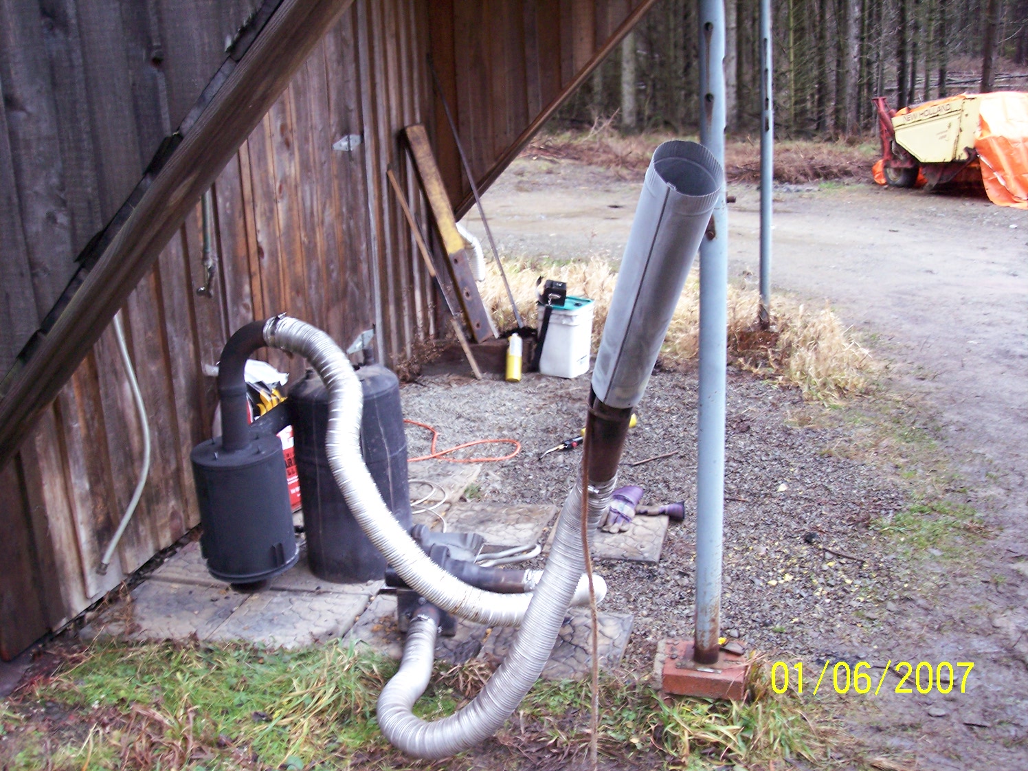
It was made from an air cleaner housing from a military gammagoat. Cone from a rusty gasoline can cut and bent into kind of a shape of a cone. Wasn’t the right proportions but the only stuff I had at the time. It was some time ago so I do not remember how well the cyclone worked.
4 Likes
Jeff; The vertical exit pipe-- does it end at that top plate or does it protrude down inside the cone inside?? TomC
1 Like
Tom, next weekend I’ll see if I can find the plans. The gasifier was trashed years ago and I’m way too old to remember.
3 Likes