Drive On Wood!
Joni gas generator, version 8.0 (GJ - 8.0)
Projects
Joni
(Yevgen Kolyvan (Ukraine))
December 19, 2020, 9:26pm
31
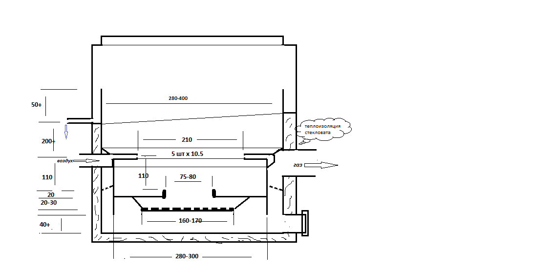
Безымянный v8.1m
1091×554 7.01 KB
14 Likes
Wood-fired gas generator Kolyvan 9.0 version
Wood-fired gas generator Kolyvan 9.0 version
show post in topic