I went and bought a snap on welder that is actually made by mostly century parts, it has 6 caps with one big resistor accrost all of them on the bus bar,so i am good on the pics, good too know them diodes like you used work good.THANKS
1 Like
I have been aware of these modifications for the little HF welder but never tried them.
Yes the welds are ugly but I just thought this was because I sucked lol.
Maybe I try this then?
I have some big Diodes from an old Exide battery chargers and some oil caps kicking around.
I noticed better wire helped.
These are the kind I have, as you can see you you need a heat sink to use these ( sold separately )
http://www.ebay.com/itm/4-NOS-1N4045-DIODES-100-Volt-275-Amp-Make-full-wave-Welding-Rectifier-/111951827161?hash=item1a10d950d9:g:TwwAAOSwdU1W-tII
Add this project to the growing list
I always come back to the old stuff.
This guy is one of the most dangerous and amusing people on Youtube.

Fins blowing up watermelons also never gets old.

Be careful out there.
1 Like
I went on that salvage mission today.
Looked at the diodes and heat sinks.
Turned my nose up at them 300 amps at 250 volt.
Massive over kill 3 phase units.
Can’t use the heat sinks too large ( big as my welder ).
I could have sworn these were much smaller.
I am going to sniff around the scarp pile from something smaller ( and less rusty too )
On the other hand I saved the shunts and metering from 3 units.
You never know when you want to monitor a battery bank.
1 Like
That was a very nice mod! I did a similar mod on my little Arksen 100 flux core. Instead of the three-phase rectifier I used diodes that were leftovers from monster DC drive repairs I’ve done. Similar diodes are available on Ebay. The single diodes can be connected to a heat sink that is also the connector for the bridge output which facilitates cooling. Three phase molded bridges are usually used for applications like small wind-driven generators that use automotive alternator parts which have low-voltage cramped three-phase rectifiers that aren’t suitable for a welder because of voltage spikes and cooling problems. Large single diodes allow each diode to essentially have its own heat sink which I make from sheet metal. My heat sinks are as large as the inside of the welder will allow and I used the standard phenolic blocks as insulators. I also cut away all but an inch of the case and installed metal screens to increase cooling and enclosed the xfmr in plastic ducting with a microwave oven tube-cooling fan mounted on one end to facilitate better cooling. I’ve been using microwave cooling fans for years and they are fantastic for cooling power supplies. I got several at a local appliance recycler for free. I threw out the original cooling fan and use two microwave cooling fans, one for xfmr and one for rectifier. A friend told me that I could increase heat sink area by bending waves into the heatsink metal, but with the new cooling system the duty cycle has increased substantially. Don’t forget to use some heat sink paste. Also large single diodes allow input and output wires to be bolted directly to the diode leads. A full-wave bridge allows both sides of a single-phase supply to be routed to the correct lead. When the wave is positive the bridge routes the current to the pos lead and vice versa. The caps smooth the waveform by discharging when the voltage decreases. Inductors do the same thing for current. It’s almost as good as connecting three 12v car batteries in series and using them to weld. If you have an oscope you can tailor the caps to suit your welder. To discharge the caps when the welder is turned off, I installed a relay that opens a circuit when the welder is turned on and shorts the cap bank across the xfmr primary when the unit is turned off and the relay is deactivated. I’ve built several large battery chargers that use SCRs to clip the input wave and thereby allow for much finer adjustments of the output voltage. My next mod will be the installation of SCRs in reverse back-to-back to to allow better adjustment than the current four-setting switch, or I could put the SCRs before the switches to allow even better adjustment. A trick with older DC drives was to use neon tubes instead of diacs as SCR triggers because you can verify SCR operation by watching the tubes. A friend asked me why I didn’t just buy an inverter welder, but what fun would that be? It’s fantastic to see people doing mods instead of just throwing something away and buying something better.
1 Like
I did a similar mod to my arksen 100 amp but instead of using the three-phase rectifier I used some left-over 200 amp diodes from a DC drive repair. Each diode uses its own heat sink so the box runs very cool. I did have to add an additional level to the welder so I would have room for the big diodes. The size and weight increase isn’t very much with the box being about ten inches taller than normal… My wire drive motor was very jerky when I pulled AC from the xfmr output directly to the speed control board. My wire was jerking all over the place and I couldn’t get a good feed rate so I took a 24 volt xfmr from an old cassette player and now the feed rate is fantastic and the welds look almost as good as when I use the monster stick welder from work. Now welding with this thing almost reminds me of using the MIG from work. I’d also recommend that you buy some good Lincoln flux wire from Lowes since the stuff that came with my welder throws sparks all over the place. I also bought a box of tips from Lowes and replaced the original. On kind of a goof, I pulled the feed from the diode pack output to a piece of wood bolted to the side of the welder with the negative lead going both to the stinger and the terminals on the outside of the welder. With the neg and pos leads accessible from the outside of the welder, I added a stick welding grip just to see if I could use 6013s and I was really amazed at how well the rods burn. I read somewhere that stick welding with the flux box wouldn’t work, but for repairs around the farm or garage it works great. The sticks weld much better when I’m welding upside down where the flux tends not to penetrate very well whereas I can shove the sticks into the weld pool and get decent adhesion. With the extra room inside of the welder cabinet I have room to keep a small tube of welding rods and an extra spool of wire. Many youtube videos show that these small welders overheat and trip after just a few minutes of use, but I welded a trailer hitch under my farm truck and the box barely got hot. I cut the side louvers out of the welder and replaced them with metal screen for better airflow.
1 Like
Hey Guys
I’m calling bullshit on this mod! I have a 20 year old gasless ac mig welder and it welds just fine! the secret ingredient/mod is practice! practice! and more practice the machine isn’t the reason your welds suck!.
1 Like
I ordered my parts today to convert my welder. One question the resistors should be installed inline or between capacitor terminals? Thanks for your help
The resistors are just there to discharge the capacitor when you finish welding and release the trigger. That eliminates the hot tip that would be there if the capacitor was left charged after welding.
Brian:
I just came across your HF mod and had one question before attempting it on mine.
My HF has a cold torch tip till the trigger is pulled, which is a vast improvement on the older models.
Are you saying that when you made the mod that Matt Heere did, that the torch tip is now “always” energized after doing this mod even when not pulling the torch trigger?
The capacitor holds a charge when the trigger is pulled until it is discharged. The purpose of the resistor is to bleed the charge from the capacitor automatically after each weld is finished. With the resistor the capacitor is discharged in a couple seconds. Without it the tip will remain hot after each weld so you would have to treat the unit like the old hot tip kind, or you could ground the tip after each weld by striking the work or the ground clamp.
Donny, sorry I missed the point of your question. The resistor should be installed across the posts of the capacitor to drain the capacitor, or short the capacitor.
Thanks for the advise. What size resistor would you use to get the quickest discharge of the cap while still being able to handle the current and voltage?
I just watched the first of the “Zero” guy’s demos (see earlier post here).
He says he used a 150 Ohm, 5 watt resistor to bleed off the capacitors. That looks about right to me to reduce 24 volts to about ((24 X (1-.63)) = ~9 volts in about 9 seconds. I think the current flowing through that resistor shouldn’t be enough to be noticed in the output of the system.
Am I missing something?
P.S. I like their idea of using those 3 phase rectifiers in a single phase rectification setup.
Pete Stanaitis
Pete
That’s a good question. I saw a post that said something about the fact that the welder did not perform well until he changed out the resistor. Unfortunately the poster never explained what he change the resistor too so I have no answer for you.
I also watched the Zero guy’s video on the mod. Did you understand the mod he did on the Wire Feed motor? I understood where one of the wires goes to the feed motor, but when he turned the welder around, he lost me on where I am to hook up the second terminal of the wire feed motor to smooth out the feed motor. Did you understand how to hook up the extra transformer to the wire feed motor?
He is running it through the primary of the second transformer, and then using the secondary of the second transformer to feed the motor. The other wire should go to ground. It seems like you could just use a big cap (+resistor) to smooth it out. It is a neat way to do it, it just seems like overkill.
I’m also not convinced the rectifier is needed. I have a hard time imagining AC with mig working at all. My guess is someone mistook pulsed DC for AC.
1 Like
Sean
This is what I gleaned from his video.
As I mentioned, I understood everything he did till he turned the welder around. It appears to me (I could be wrong) that the 120 volt hot side is being feed by tapping into the trigger relay and then he is tapping into a neutral wire somewhere on the back side. Since he mentioned the Fan, I assume he figured out which wire going to the fan was the neutral and tapped the other side of the primary into that.
Is my diagram correct to what he was doing?
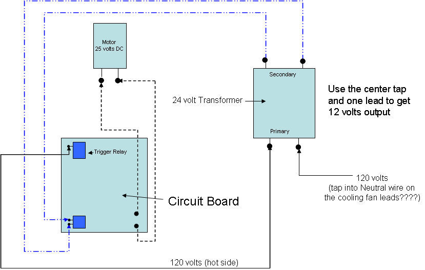
I am a bit confused too.  He is splicing the main transformer primary after the switch relay as the primary to the second transformer, and connecting the two secondary wires of the 2nd transformer to the motor. Which he said he was going to change 1 of the wires to the center tap to get 12v. I assume the pot/transistor for the wirespeed is -after- where he cut the wires from the board.
http://jacobs-online.biz/understanding_transformers.htm
I am a bit unsure about the toroid inductor, and that maybe why they have the rectifier to protect the main transformer from back current. You can use bare grounding wire then coat it, or you can run multiple smaller wires in parallel for the same effect.
Given I have seen 3 different schematics for the welder, I would put a multimeter on the transformer output leads to see if it is pulsed dc or ac. IIRC ac will show up as both positive and negative using the dc setting on the multimeter and pulsed dc will just go to 0 (at least on my multimeter.) I am guessing the rectifier is built in the power supply and that is why it isn’t showing in the schematic, but I could be wrong.
I just watched "Zero"s video for the third time. I have watched other videos that he has made (dealing with induction heating) and he is a pretty smart guy. I think he is correct in that the welder, as received, IS indeed an AC output machine. I also looked up specs on it and they say “duty cycle 20% @ 90 AC amps”.
It probably would be best to do a screen capture of the schematic that he shows at the beginning of his video, rather than attempting to redraw parts of it.
Then watch the video again try to follow what he SAYS, making notes as you go right on that schematic.
You WILL have to draw in a few things (that are missing from the schematic) as you go.
Another approach, depending on your comfort with electrical circuits like these, might be to start by simply making the DC rectifier change first. That one looks pretty straight forward. Then see if that works okay. Then move on to the next change, etc..
I have one of the very much older versions of that welder, so old that it doesn’t have any wire speed control at all. It also has the “hot” gun, but I put up with it in the few cases where I can’t get my old BetaMig 250 close enough.
Pete Stanaitis
If you already have one of these welders, the users manual has a schematic toward the end of it. That should help you to understand what’s in there as you get it (before any modifications).
And— if you don’t have the manual, you can always get an electronic copy by going to the Harbor Freight listing for that product. Go down toward the bottom of the page and you will find an area that has clickable tabs like this:
Customer overview, Product Reviews, Warranty, User Manual and Quick Start Guide, Buying Guide.
Click the "User Manual’ tab and you get the manual. The schematic is toward the end of it.
I make no guarantee that your machine will exactly fit, but it’s worth a look.
Pete Stanaitis
Actually I believe he is still letting the two leads connected to the main circuit board connect to the wire feed motor. Then I believe he has one of the leads from the second transformer’s primary side spliced into the trigger relay. The two leads from the second transformer’s secondary side appears to be connected to the circuit board. That leaves one lead from the second transformer primary connection. This seems to be the mystery lead.
Obviously I could be all wrong about theses connection points. He seem to show his handy work as if everyone knew what he had done instead of teaching, but following him along, the above diagram appears to be correct.
If anyone knows for sure, we would all like to know.