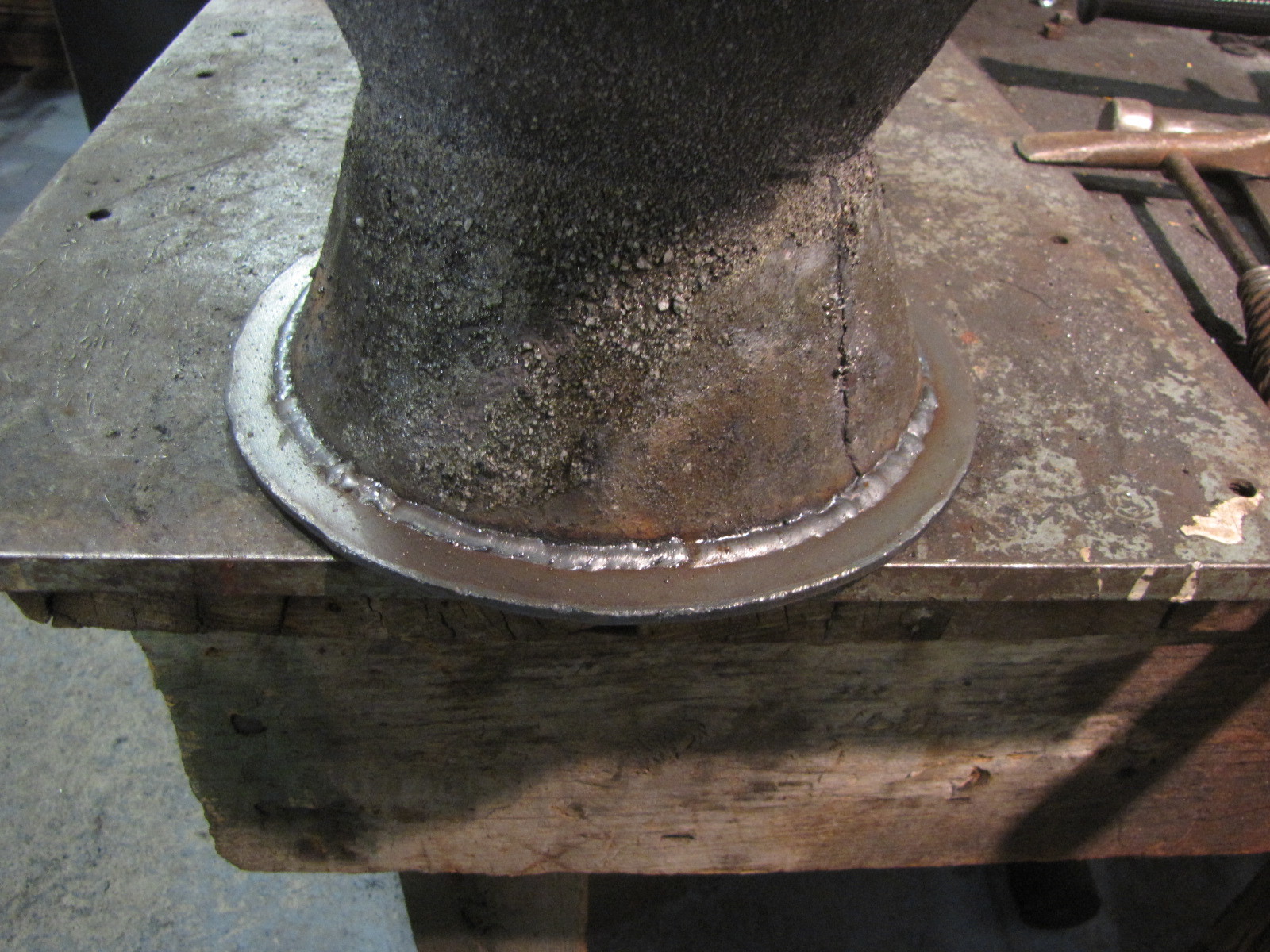
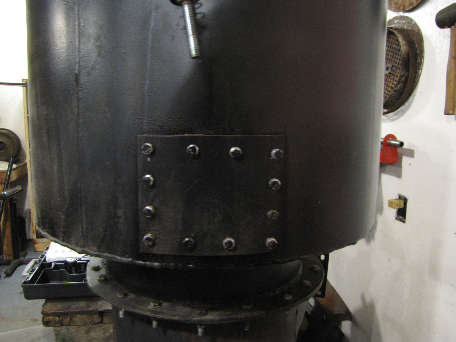
This is using a new gasket material Tom C. suggested. Used 1/16" high temp flat gasket smeared on both sides with Flamebuster latex caulk. It’s hard but it sealed great and took the heat. The heat shield extensions were definitely worth the effort. Yes, I’ll have to redo this gasket on each teardown. Gosh, what a chore, I don’t know if I can take anymore! ha,ha. It’s really a pleasure to make changes that work well.
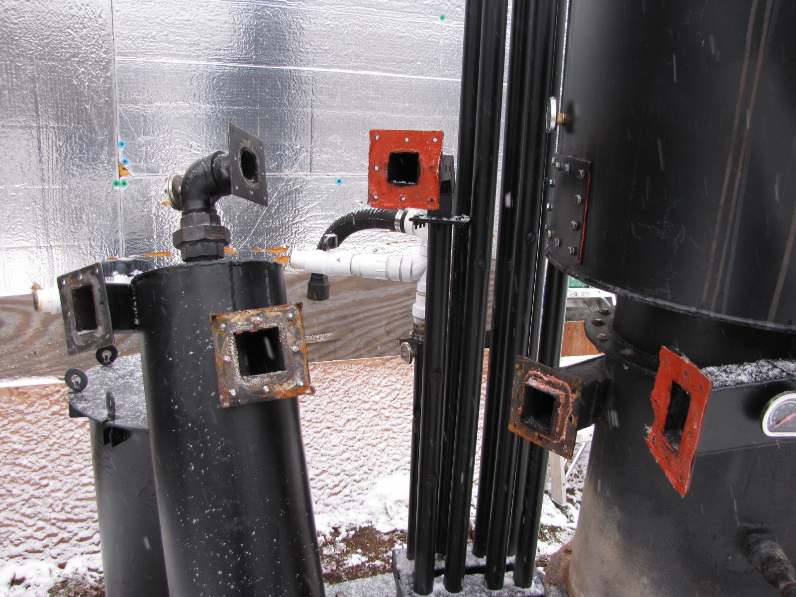
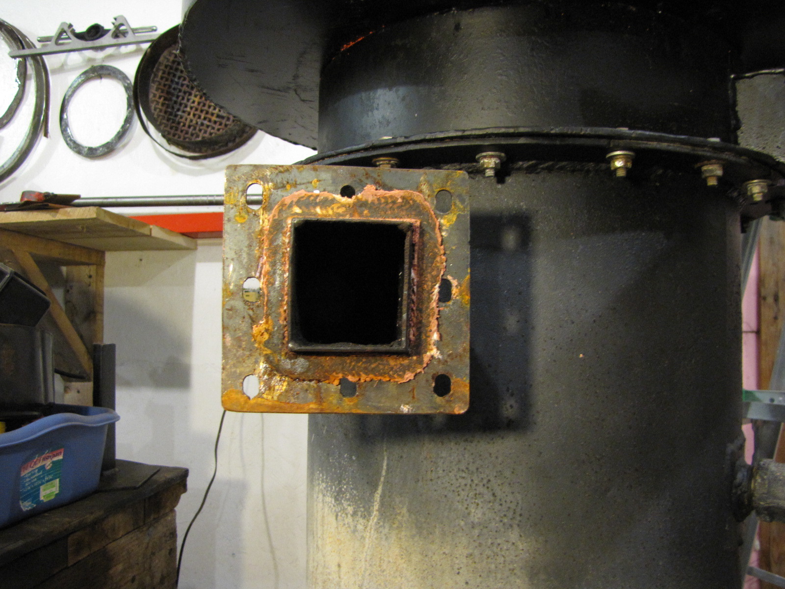
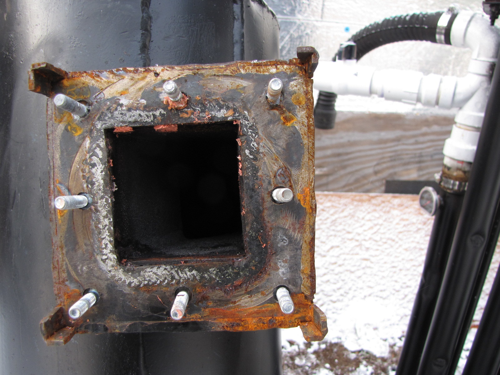
This is the old connection. I moved the gasket to other mating face protected by the extensions. I then cut out the sides leaving just the corners for line up assembly. No more heat trap here to destroy the gasket material.
Hi All,
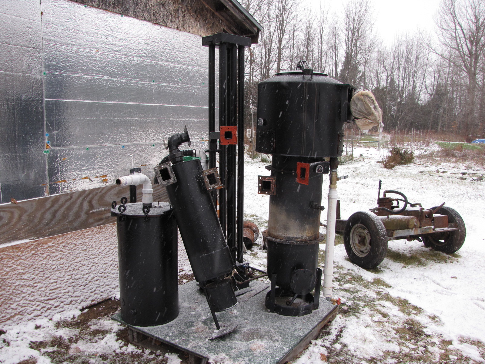
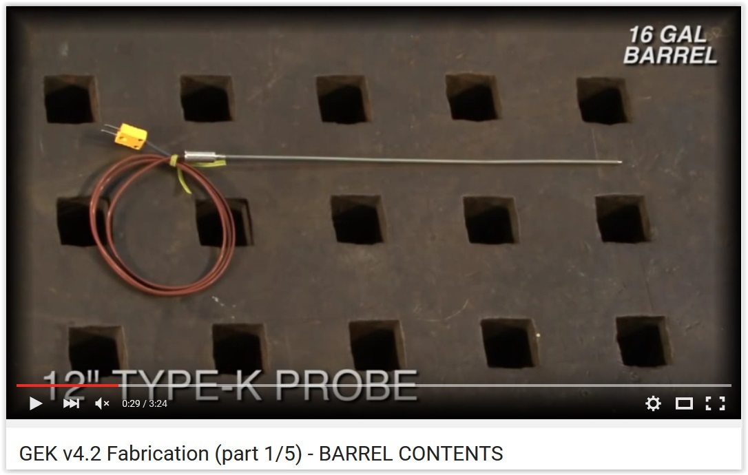
Here are some highlights of what I will be doing this winter to improve the performance of my unit. I’m sure some of you are as interested as I am in monitoring the temp at the restriction. There are other spots, too, but this is most interesting to me.
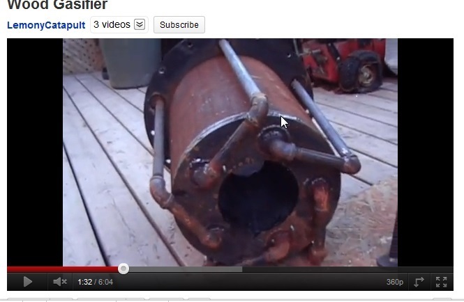
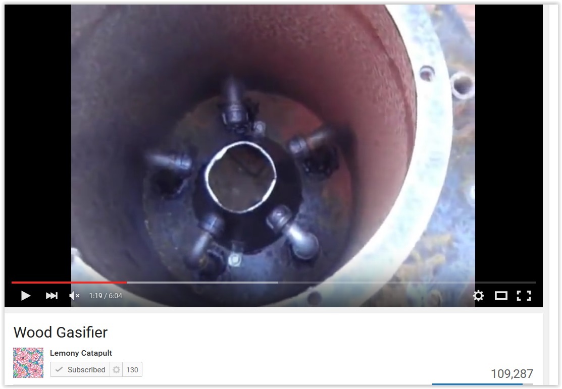
Looking for an alternative to the Fluidyne, I ran across Jim Mason’s AllPowerLabs and the GEK design. Youtube yielded this GEK derivitive posted by Lemonycatapult.
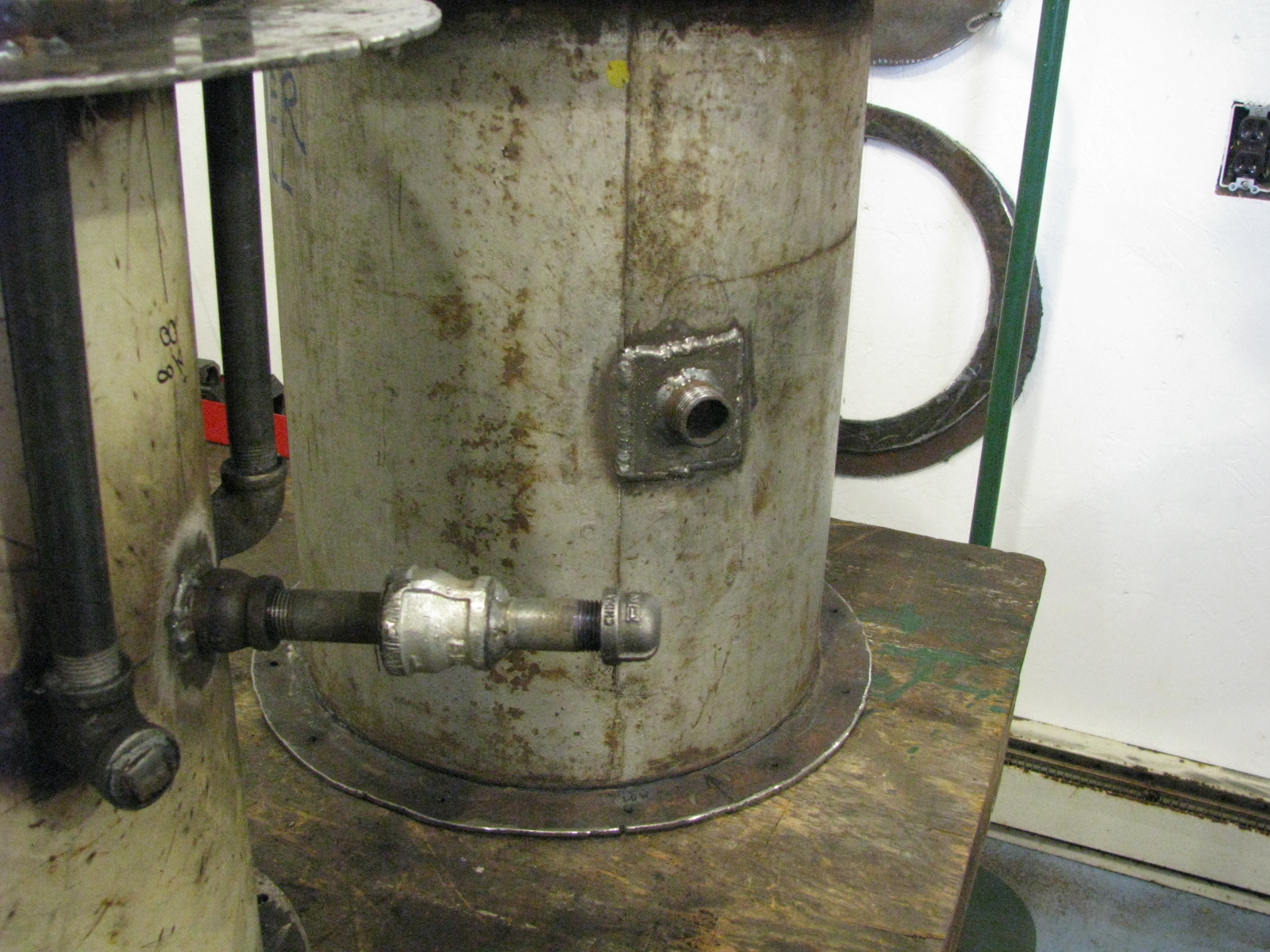
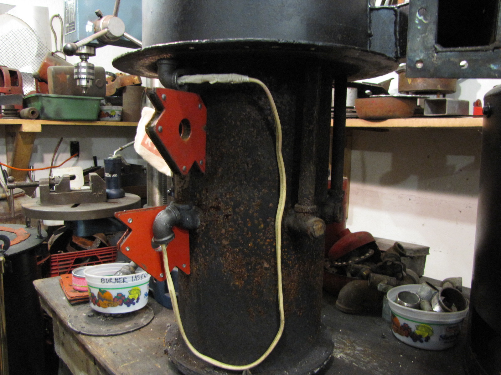
1c. My lines come through the firetube wall via a threaded 90 degree elbow. The nozzle is a 1/2" pipe cap drilled with a 1/4" hole and threaded on to a short nipple which engages the threaded elbow. Next time I would come through the wall with a 1/2" threaded pipe coupling. It would be easier to establish the nozzle ring diameter. I think it would easier to remove items from also.
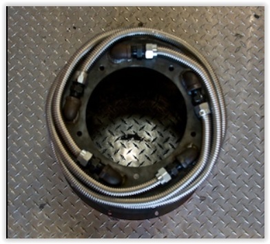
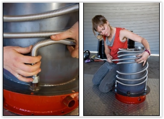
1d, 2. I will use 1’2" or 5/8" soft roll copper to make a preheat system like this.
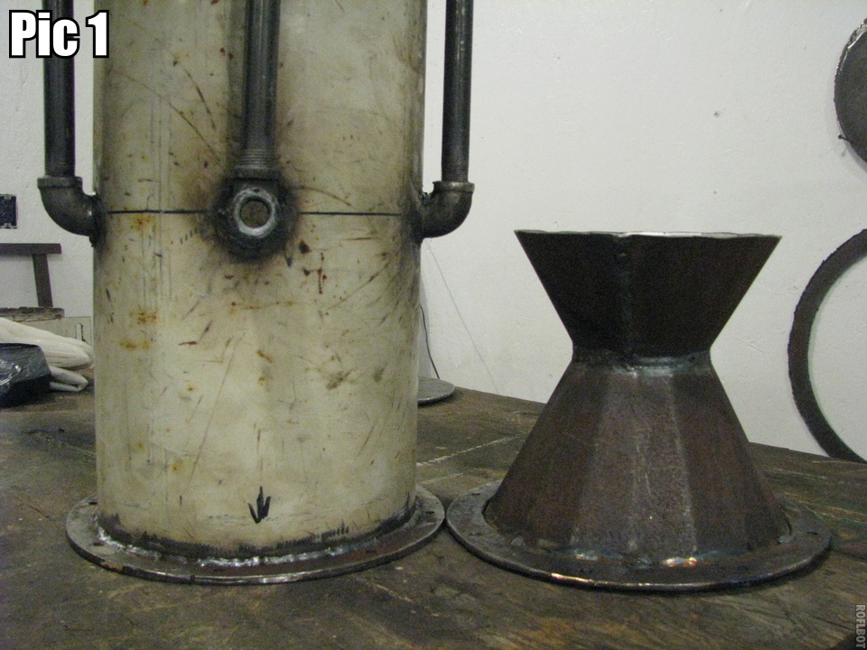
One thing I like about the removable hourglass hearth is that I can fashion cones for diff gas/hp rqmts. I have one for line C and line D on the imbert chart. Of course you are stuck with the diams of your housings/firetube. I couldn’t meet all specs, but was pretty close and got real good results. So play with the numbers a bit if you like, but build your first one as close as possible to the “numbers” so you have an accurate base for comparison. My numbers are working great,imo, so I’m not changing them.
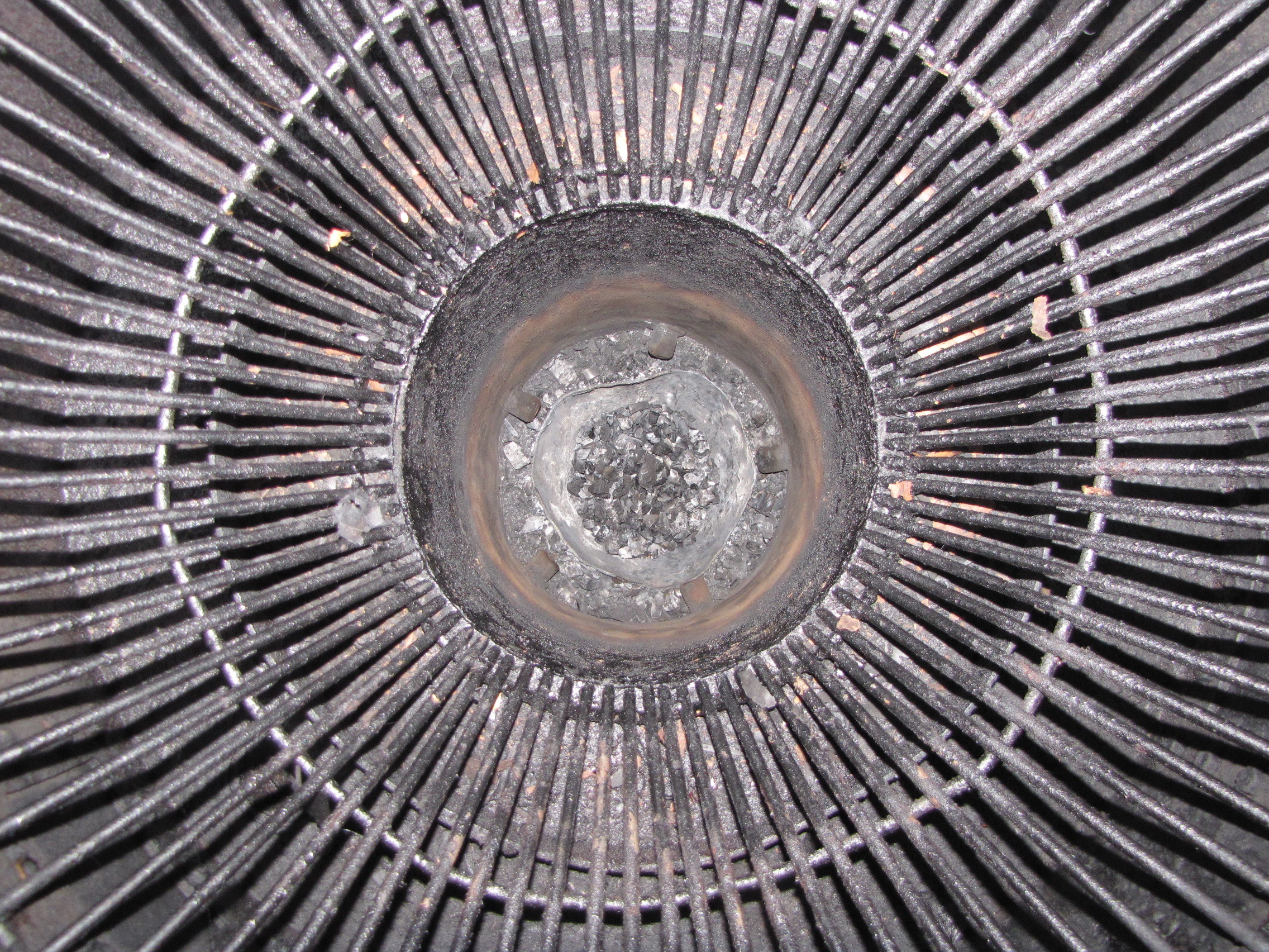
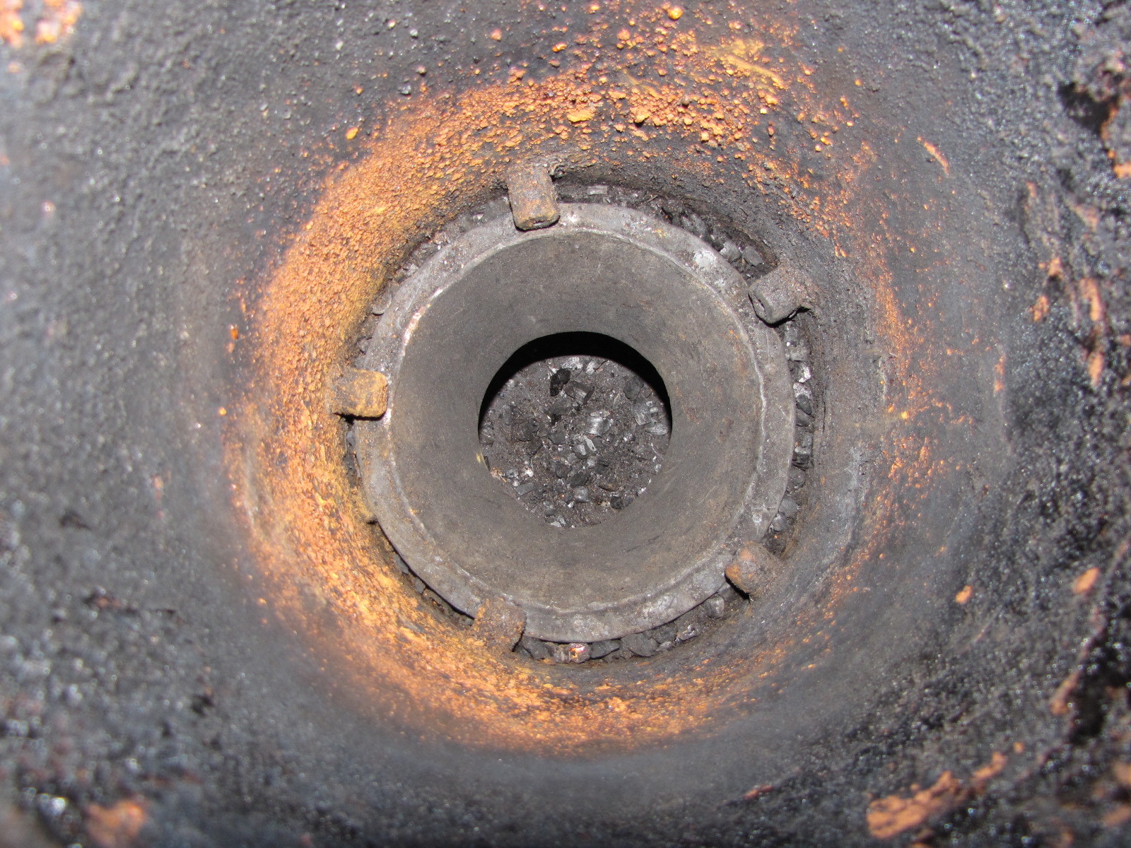
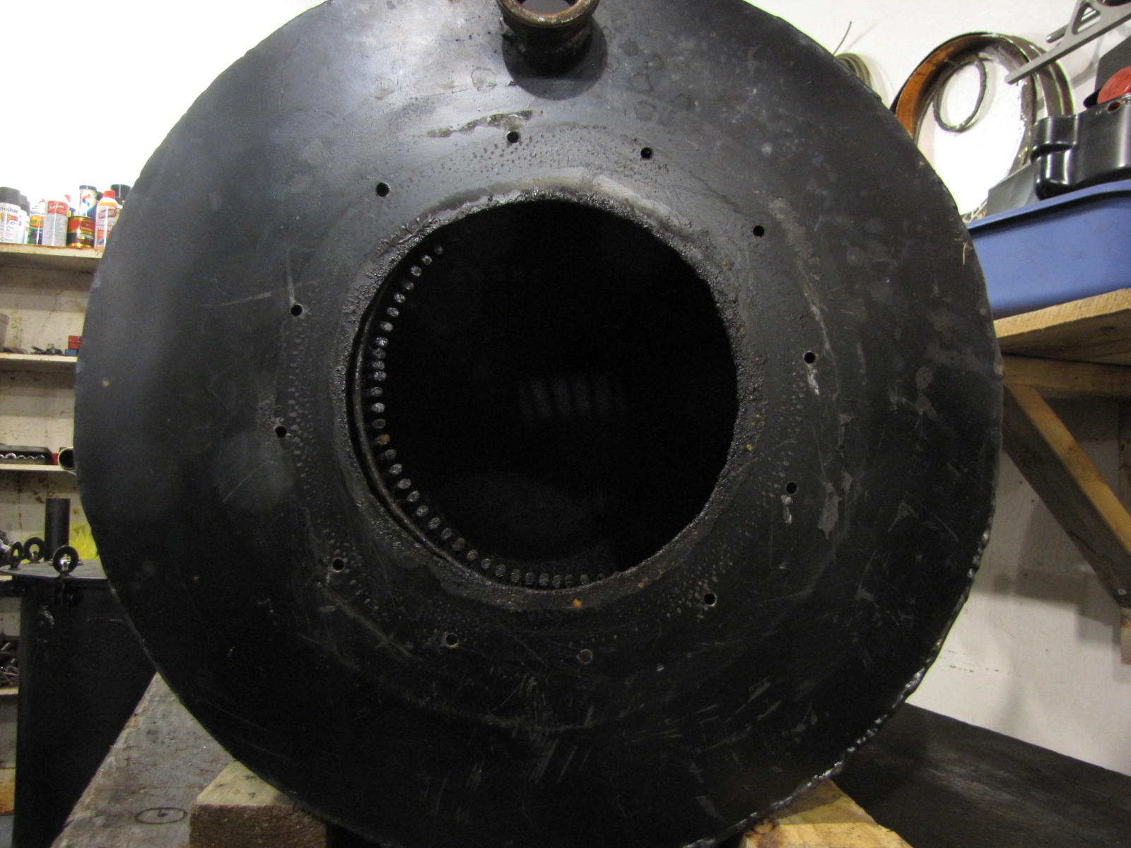
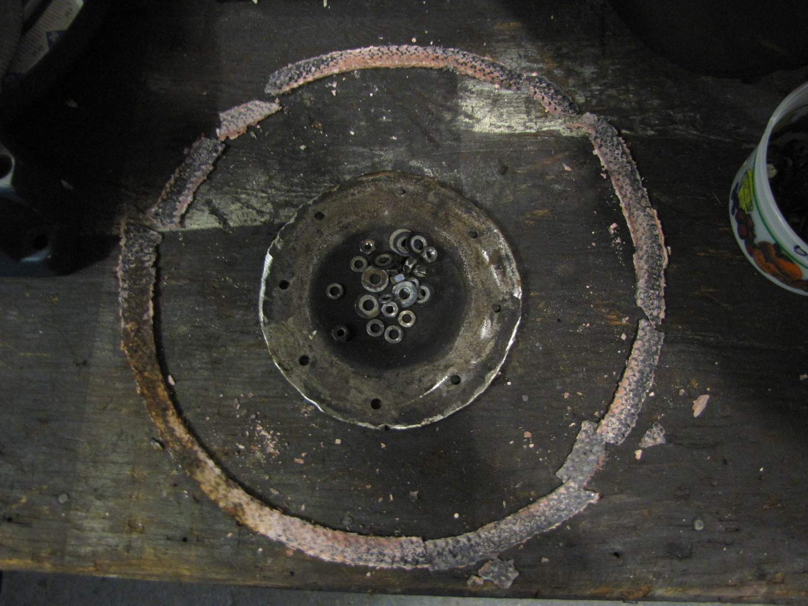
Well, there’s a bright spot in this mess. Can you see it? How about melted steel. I’d say that’s an indication the temp there was approaching 2600* F, the melting point of mild steel. A wow moment for me.
The hearth after 2015 operation. I recorded some of my hottest temps in my monitoring this summer , so I’m really pleased with the performance of my Fix.
Stay tuned for the rest of the story. Man, I liked listening to that guy. Oh, Paul Harvey btw.
Pepe
Pepe,
How much time do you think you have running the gasifier to get to this point? I’ve seen the video of you running a tiller before. Is there a particular engine you run with it?
Thanks for the pictures
Hi Bill,
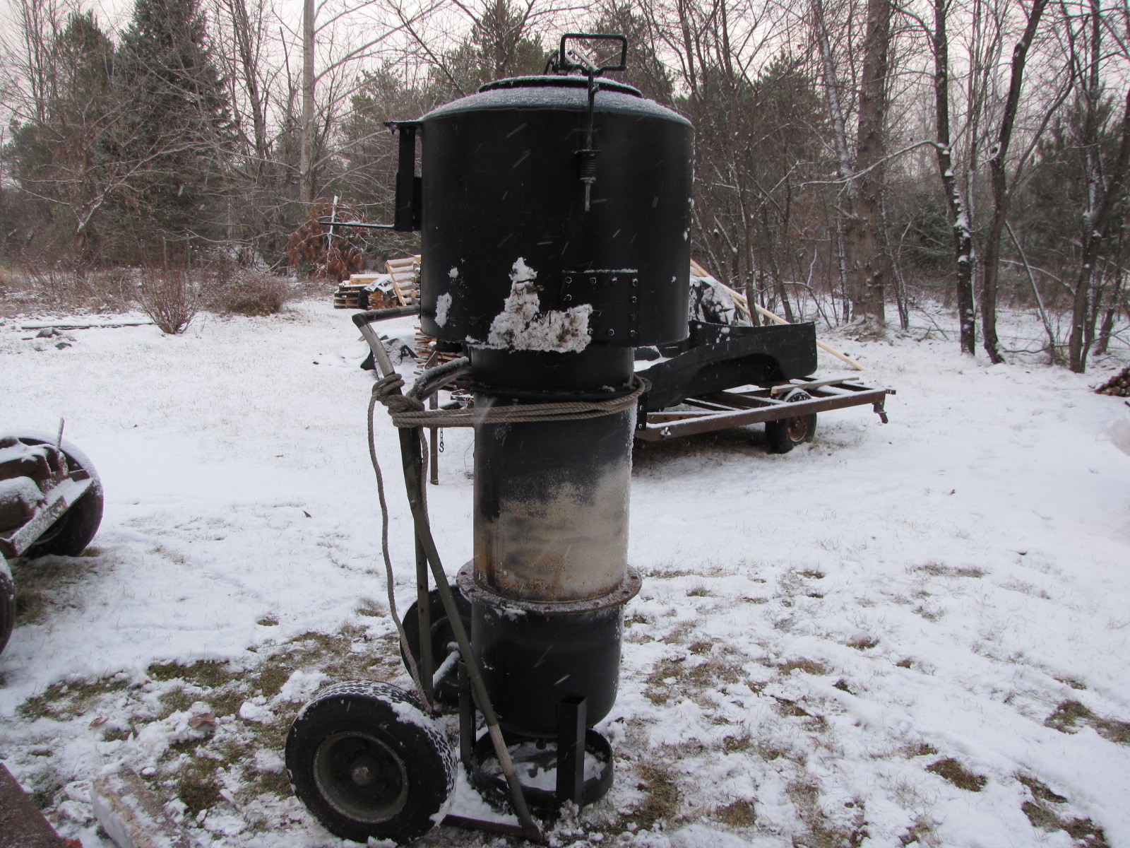
Well, as a hobbiest and gasifier fan I have probably 60 or so hrs of run time on several engines. The small rototiller is 5 hp, the snow blower is 8 hp. I have a 13 hp generator that I will sacrifice, er, run this spring so I can see how the gasifier responds to loading. The small rototiller is the only one that I ran with a load so far and it responded pretty good despite under pulling. My imbert dimensions are line D, good for 45 HP. I’ve been toying with the idea of building a line A gasifier good for 15 HP which would be more in line with the HP range I’m working with. It would also be a much smaller unit. My brother offered me a good running 1964 4WD Scout for free. It has 92 HP and would require a line K imbert gasifier. Time, time, time. I’ve been busy keeping 4 rentals going in Tupper Lake. Time to sell!
Pepe
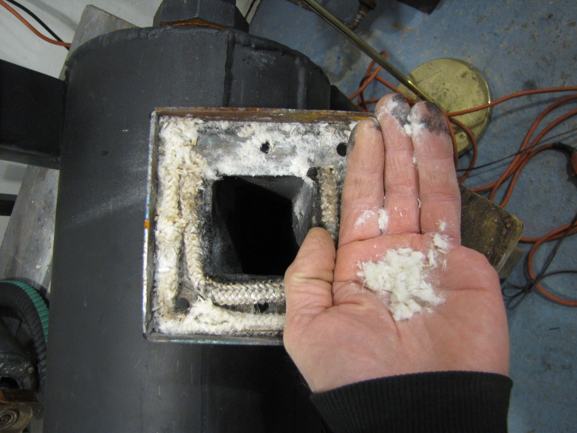
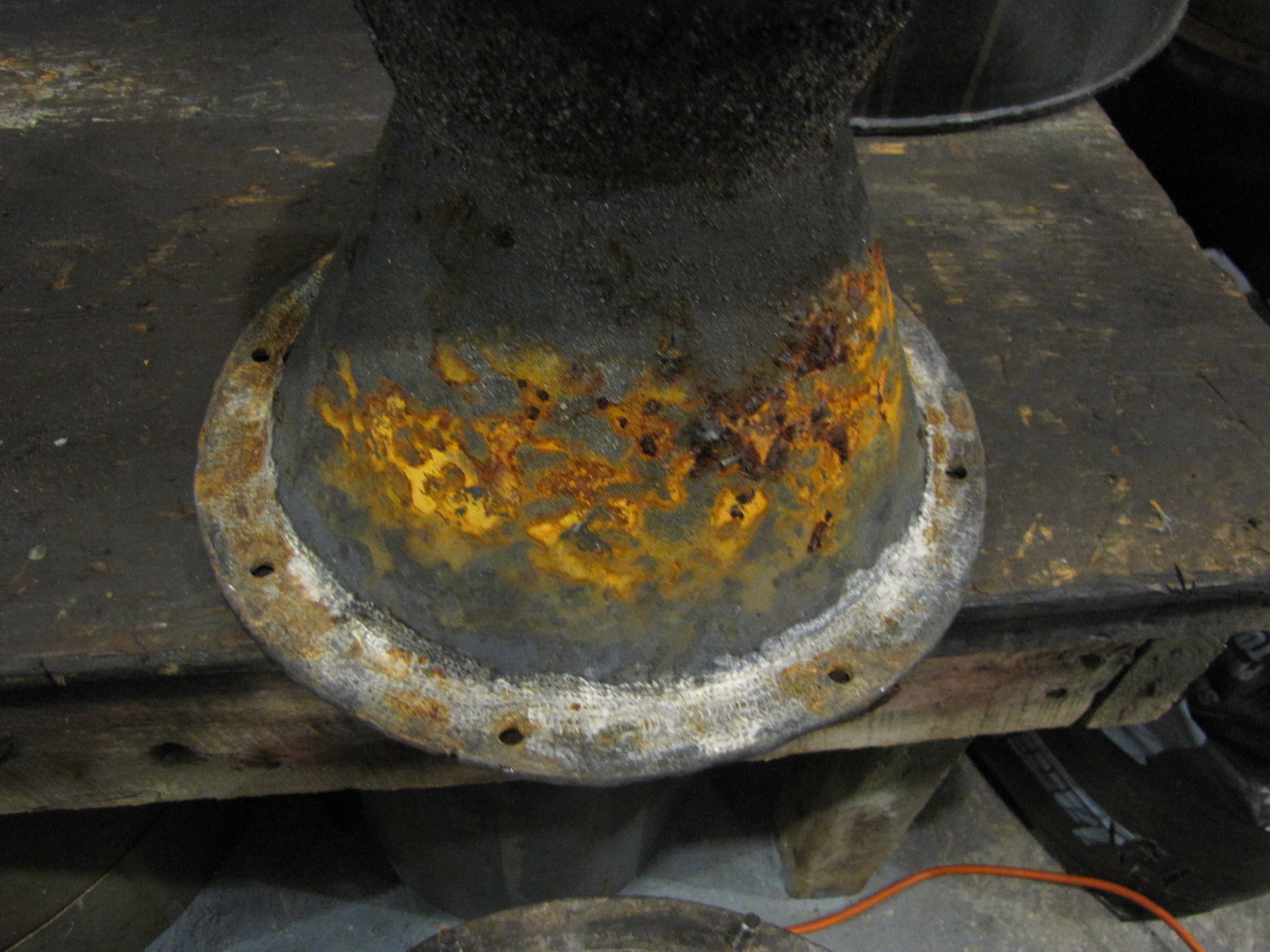
Hopper to burner shell gasket. This is fiberglass stove gasket impregnated with 600*F red silicone. Worked well, came off easily with a thin putty knife and no evidence of leak trails across the gasket faces. I will clean it up with lacquer thinner, skim coat it to smooth it over, let it set and reuse it. No leak trails on the hopper connection.
Burner insert to burner shell gasket. This is 1/2" fiberglass stove gasket impregnated with Flamebuster suggested by Tom Collins. This held up well with no evidence of leaks. This is hard as Tom said, but it didn’t leak an iota. It cracked when I separated the parts and broke up when I removed it. This came off quite easily, didn’t seem “glued” to the surfaces.
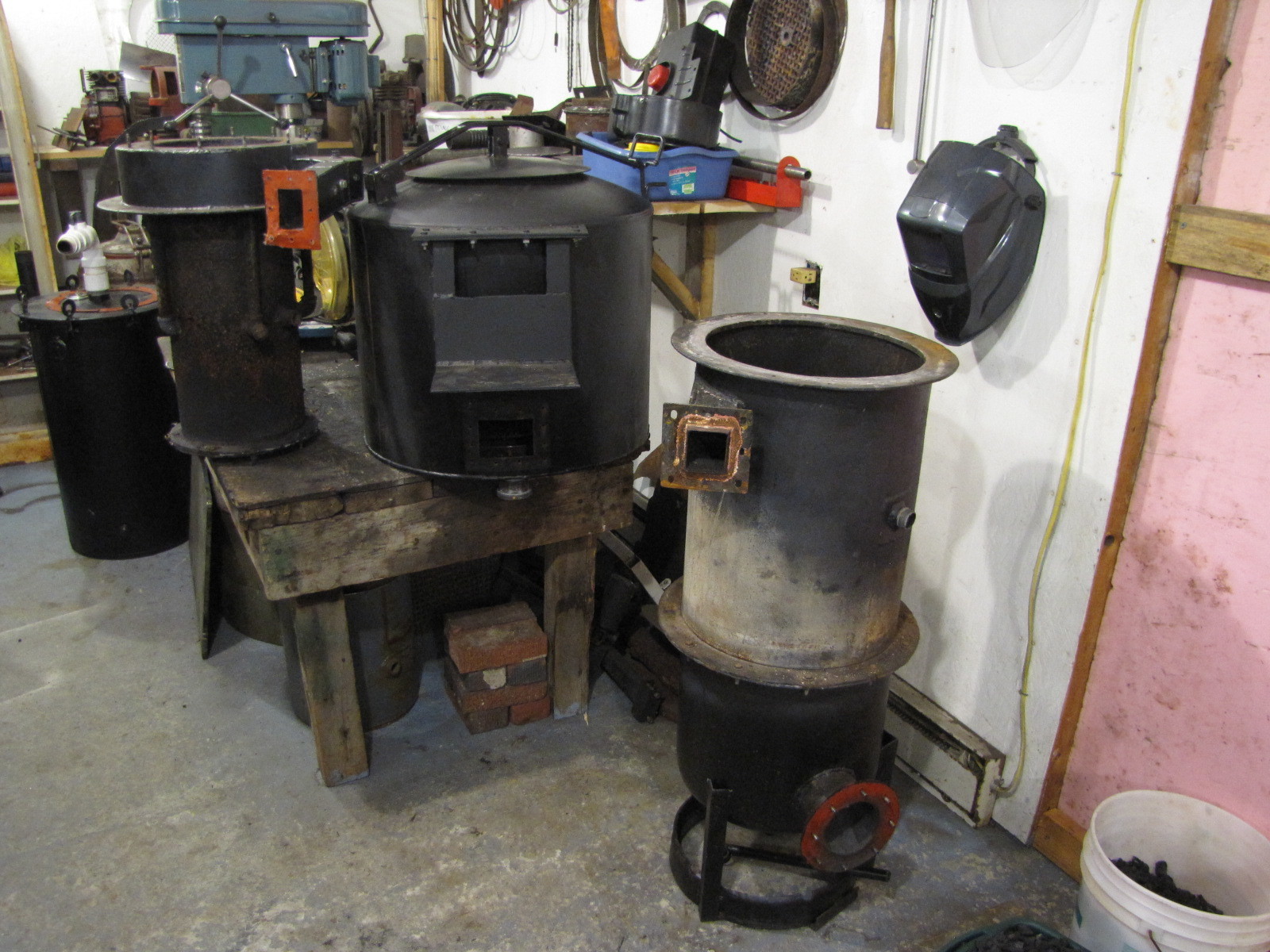
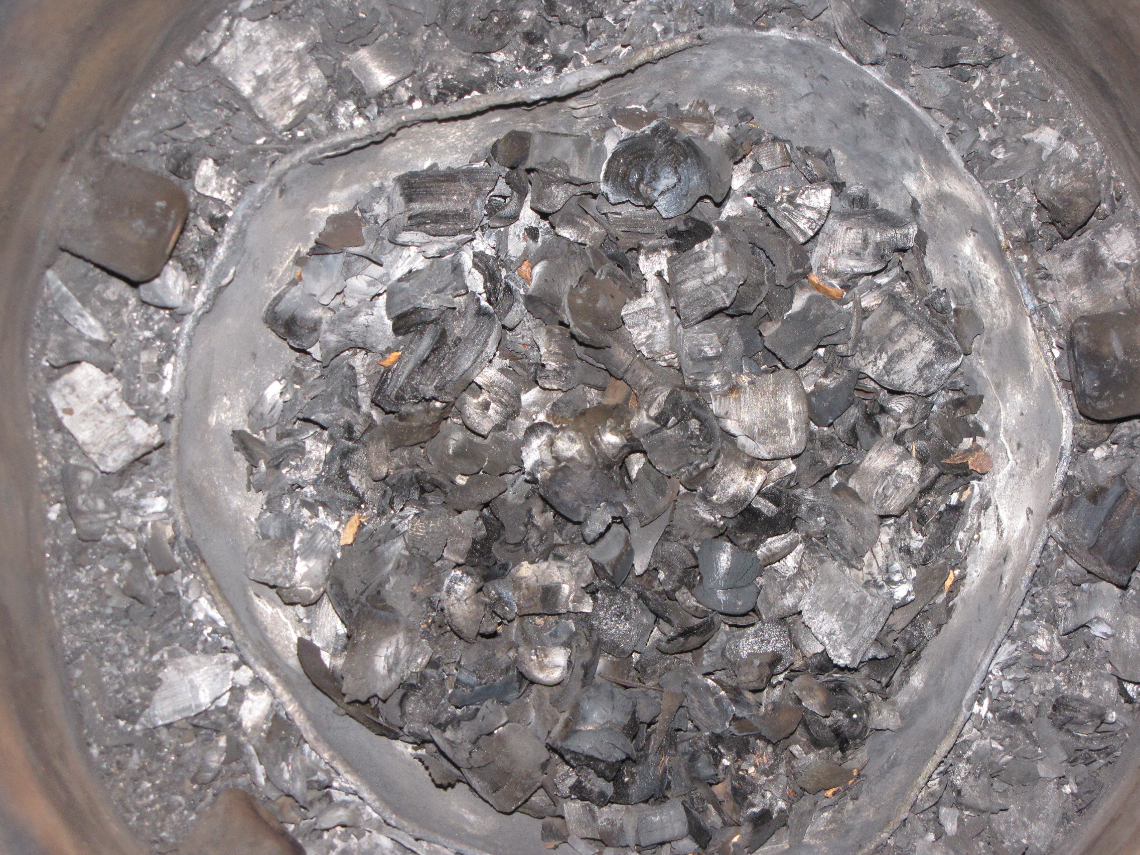
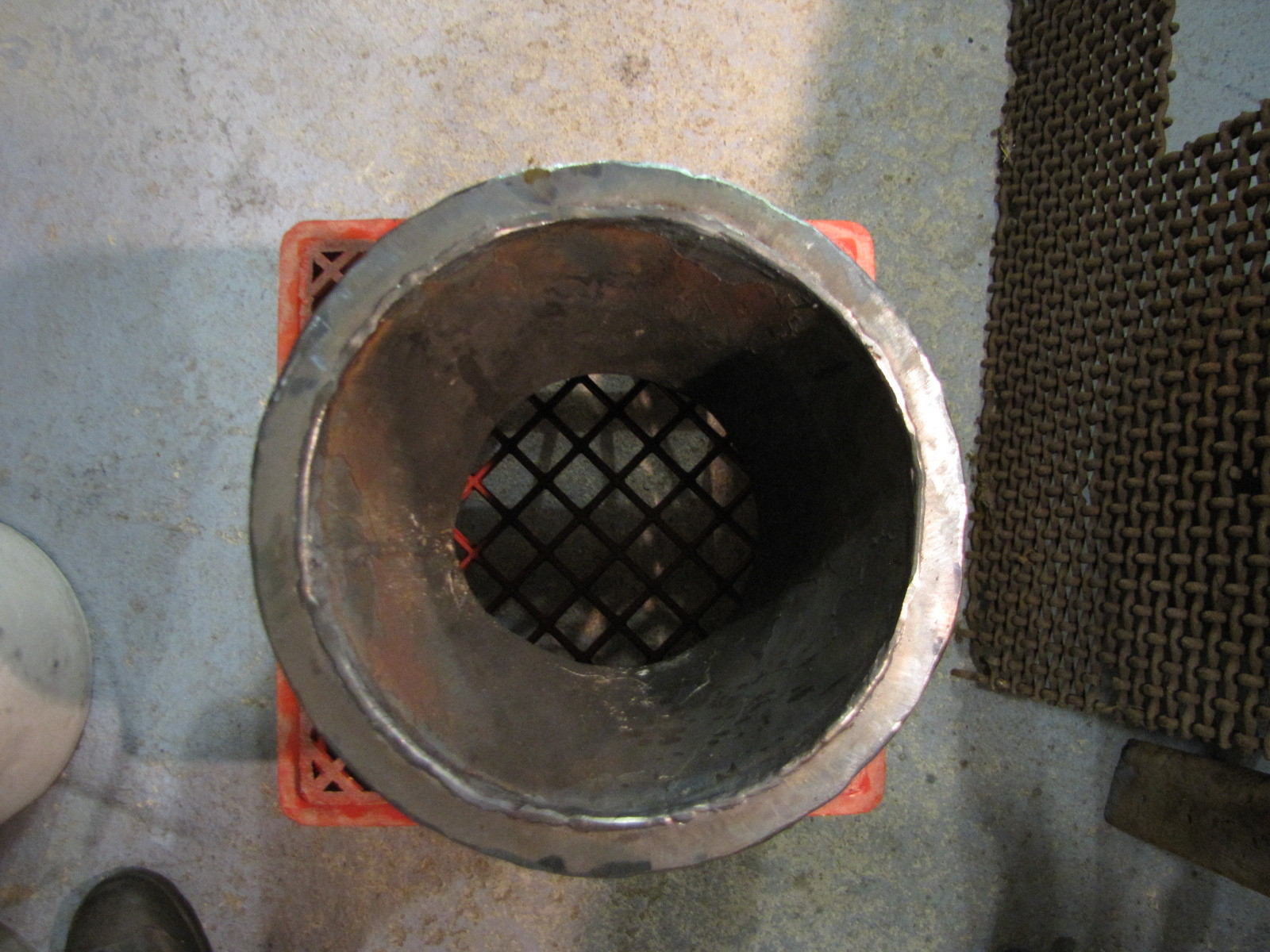
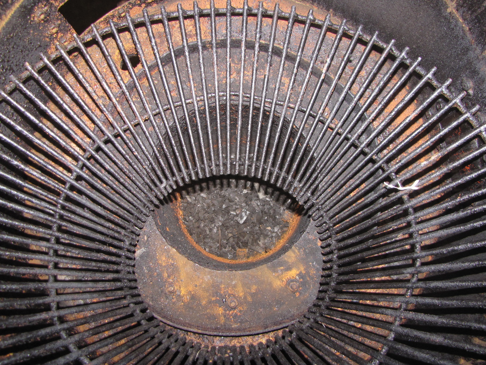
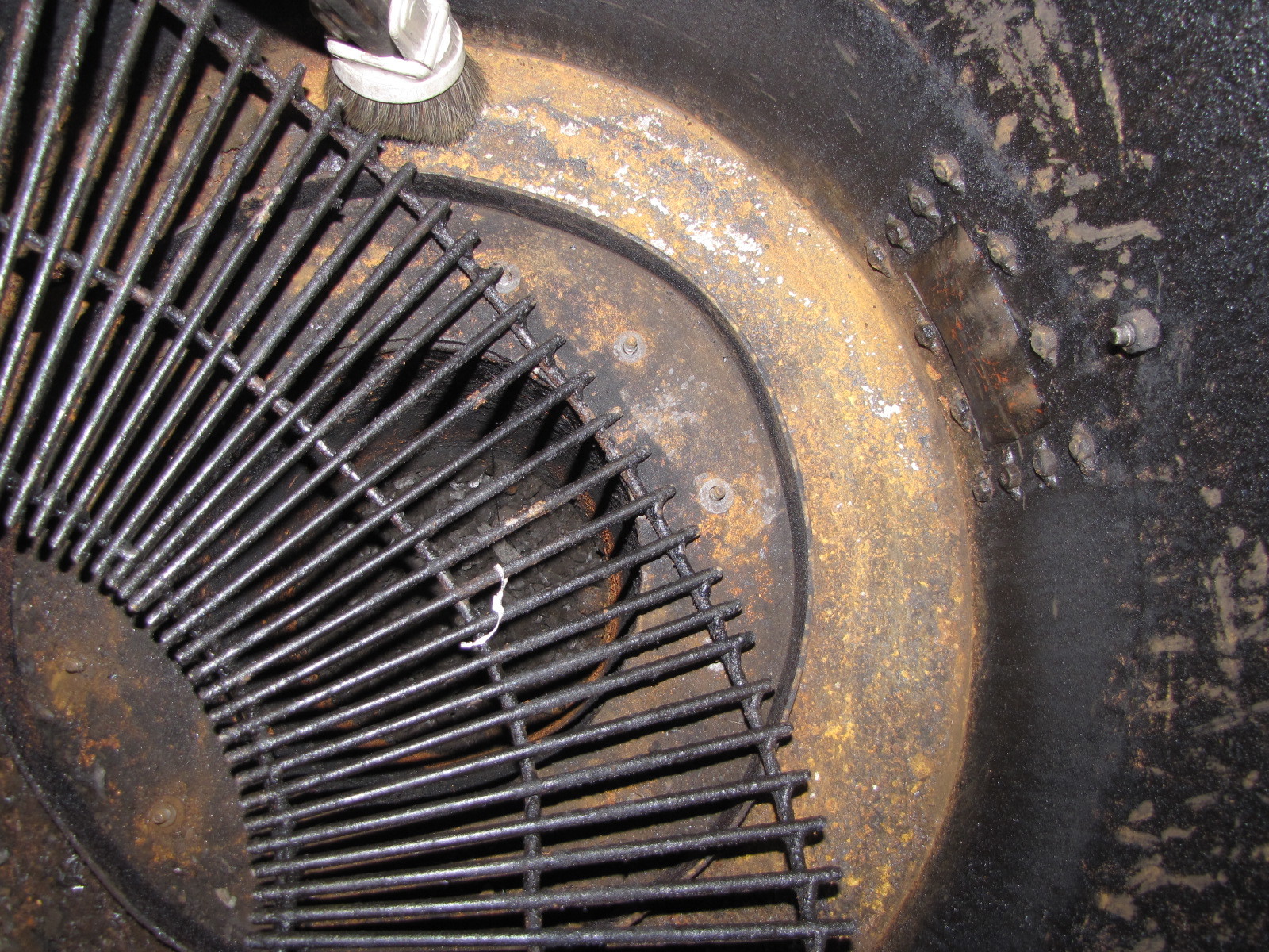
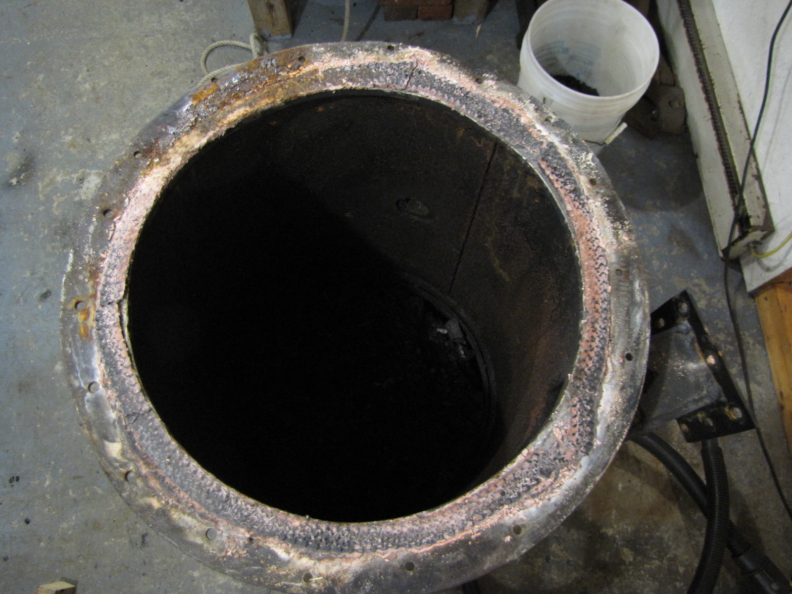
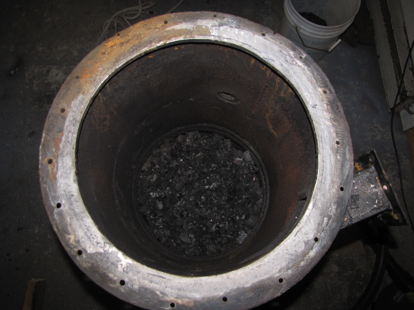
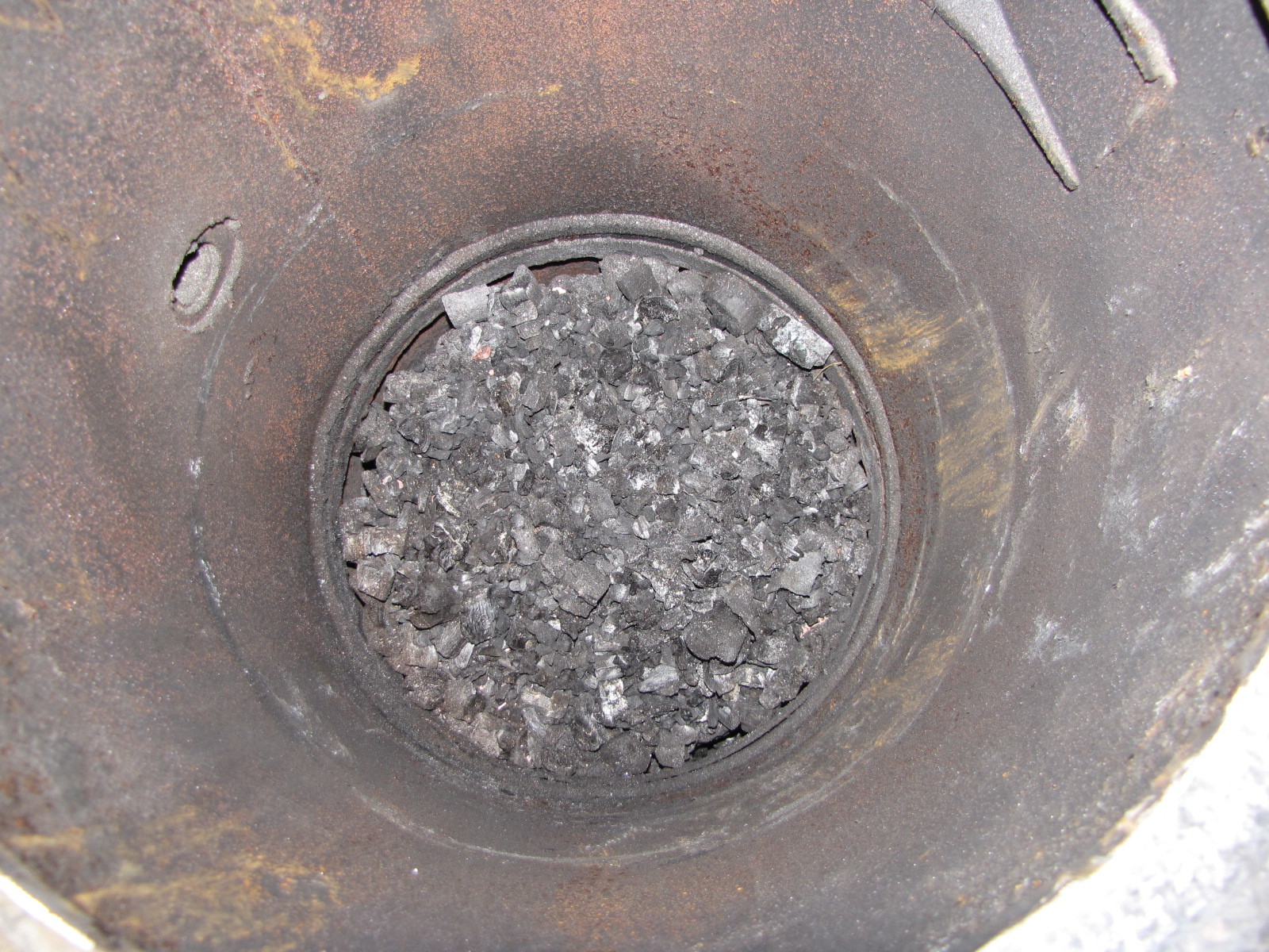
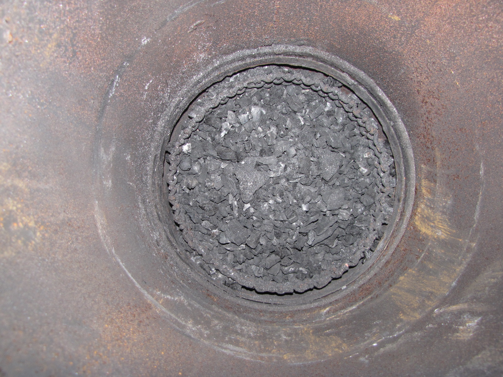
The new heavy screen basket type grate under the hourglass hearth holds a very large amount of glowing char in the reduction zone. With the hourglass hearth gasketed and bolted to the firetube, the gas has only one way to exit, through the restriction.
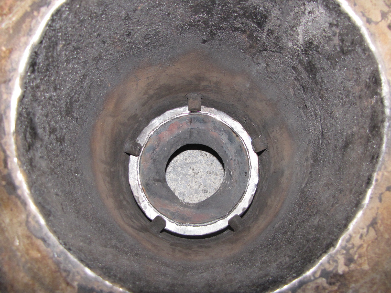
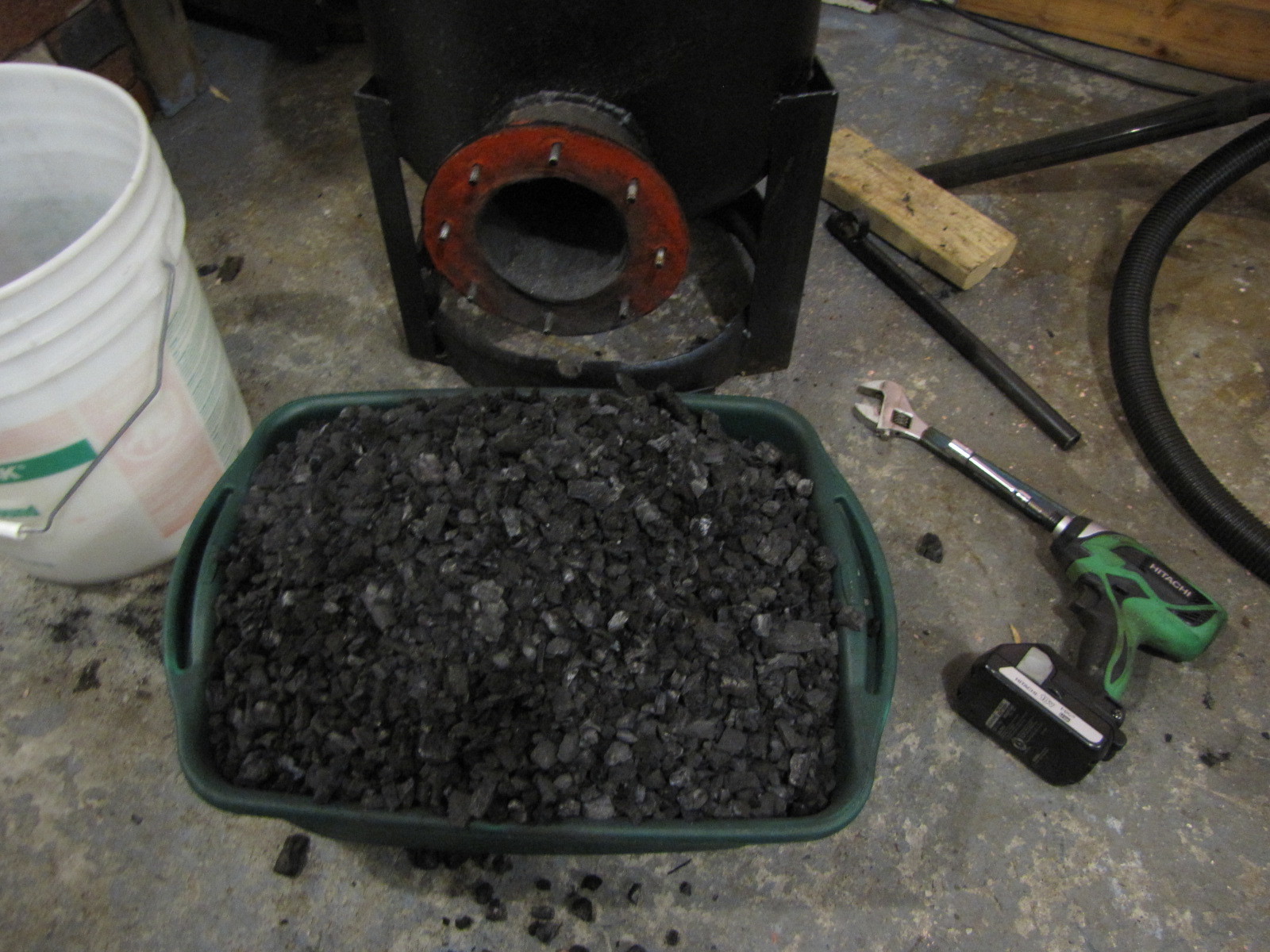
Note the char build up under the grate. This is probably 12 hrs or so of burn. Another part of the 75%, learn when to do a clean out before the buildup interferes with the free flow of gas through the char bed on the grate. Interesting, I’ll have to watch my burn videos again and see if some swirl burner anomalies started. Maybe color change, size of swirl burner flame, increasing?, decreasing? I’ll let you know if I find anything. This pan is holding 6 gallons! This had to have some adverse affect gas/flame color/size,etc. I’ll do some single fire cleanouts. Start clean, weigh it in, weigh it out. It’ll probably surprise me.
Pepe
Look at all that nice charcoal. That is perfect for running a Gilmore Simple-fier. That would be something that would be better to run small one cylinder engines on AND ----- much simpler to build that another Imbert. That beautiful charcoal is the reason I posted that design with another nozzle under the grate pointing up ---- to try and burn that charcoal into more CO. Looking good Pepe TomC
Hey All,
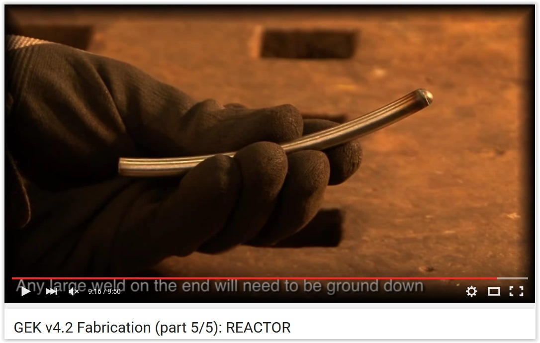
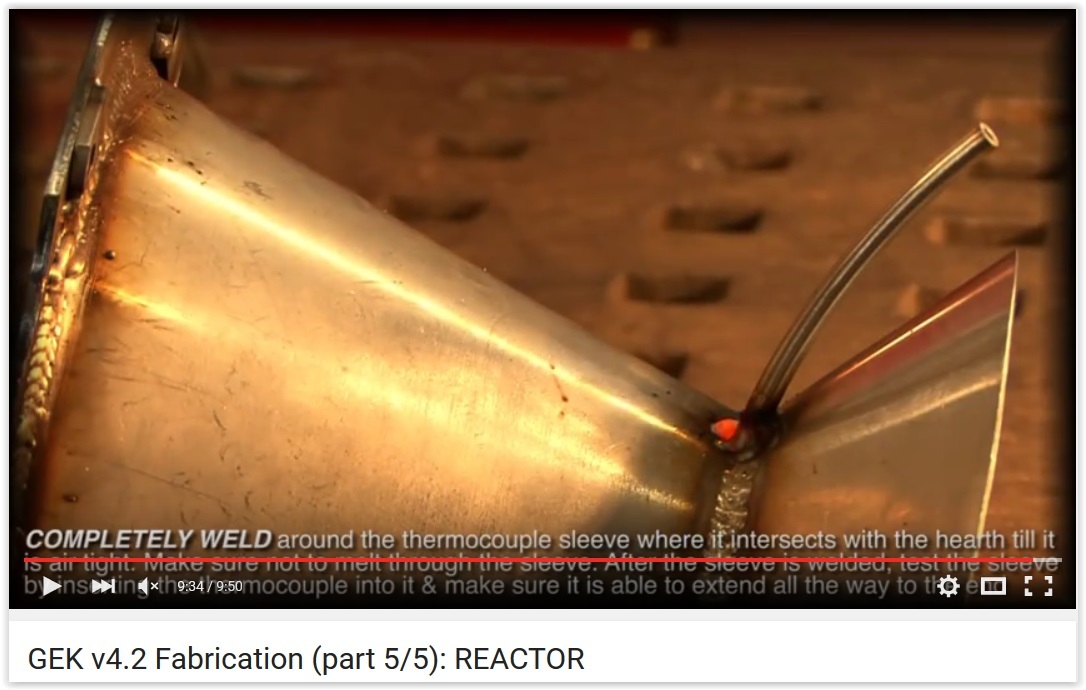
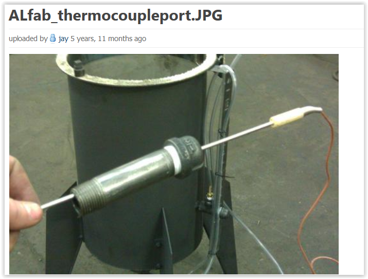
I mistakenly posted this under another topic to illustrate a possible shielding device for the charcoal gasifier thermocouple. This shows the installation process for a thermocouple for my GEK derivative gasifier, one of the improvements I mentioned that I will add this winter.
Hi All,
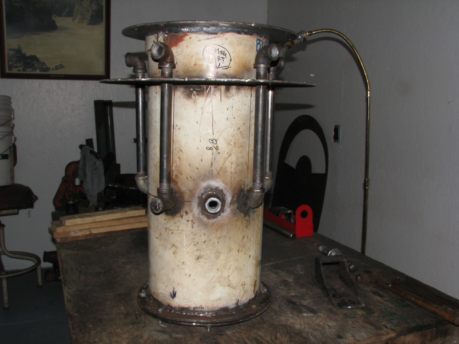
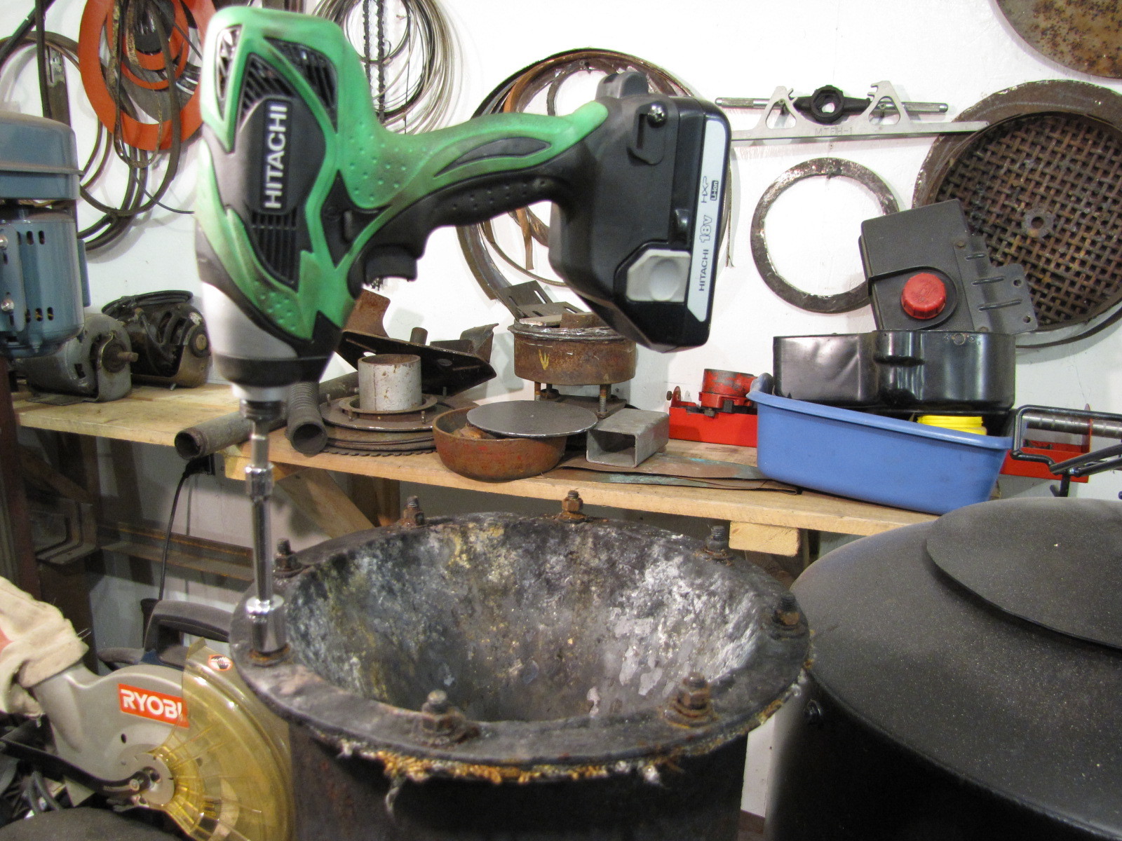
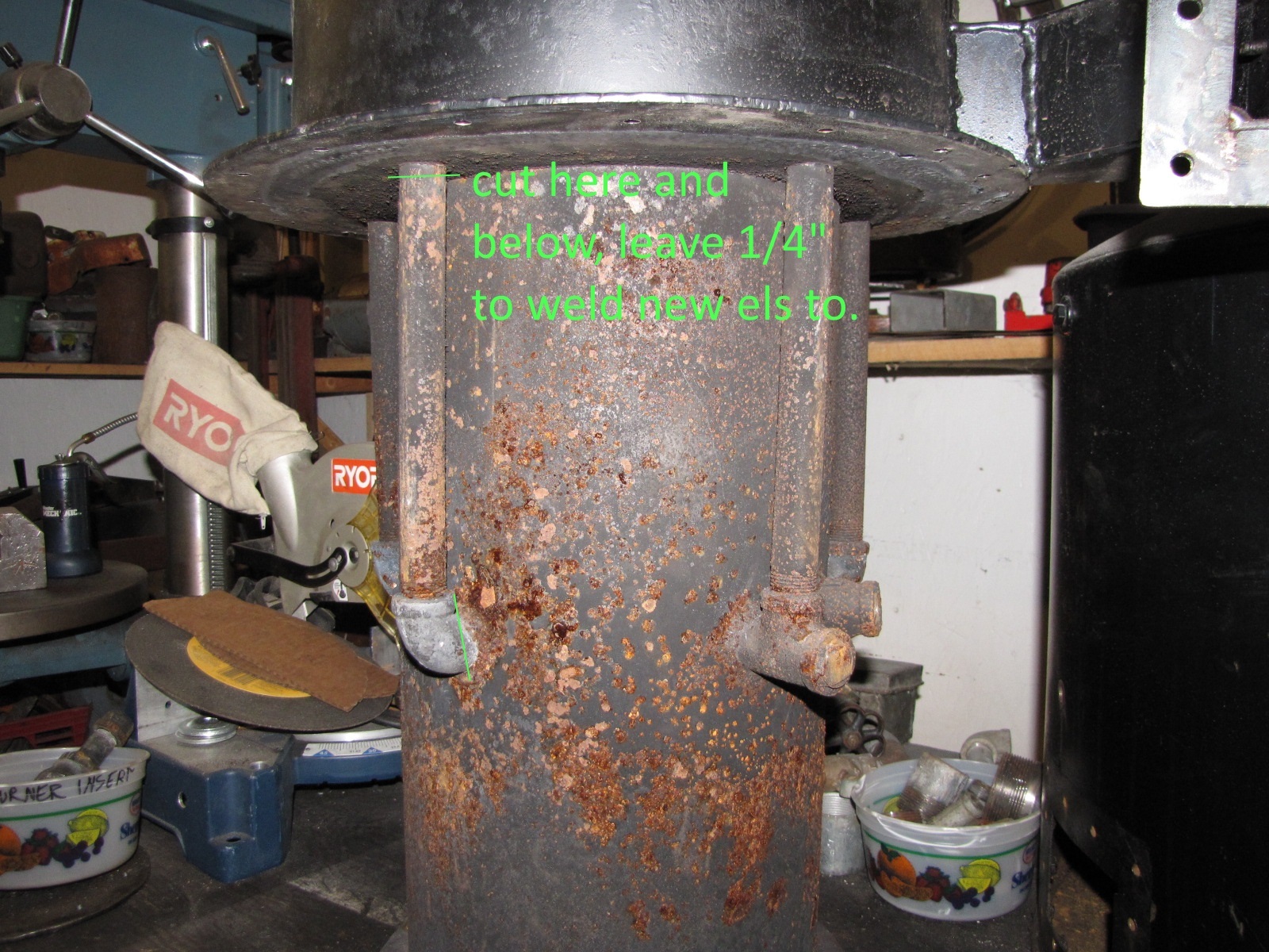
Finally got the rentals up to snuff and no vacancies. Now I can begin my gasifier upgrades starting with lengthening the internal air intake pipes.
I used this gasket material smeared with FlameBuster caulk and it worked great. This application got very hard and had to be chipped off. It stuck well. The nice thing about this material is that you can easily fit it over the bolt studs to hold it in place.
This design doesn’t lend itself well to previously posted intentions of having a permanently mounted temp sensor at the hearth constriction. I will simply use the lighting port and insert the sensor and measure the temp at the core of the combustion zone occasionally. New gasifier will have probe at the restriction. To see how I made the through the shell ignition port see comment 272 here.
This configuration will triple the length of the 1/2" iron intake tubes further increasing the temp of the preheated air. Ten inches to almost 32 inches. Will be using 1/2" ID soft roll copper and brass flare fittings. I’ll be using a homemade bending jig and filling the tubing with sand to prevent kinking. Hopefully, I’ll be able to make the half loop with its 6" diameter. We’ll see.
.
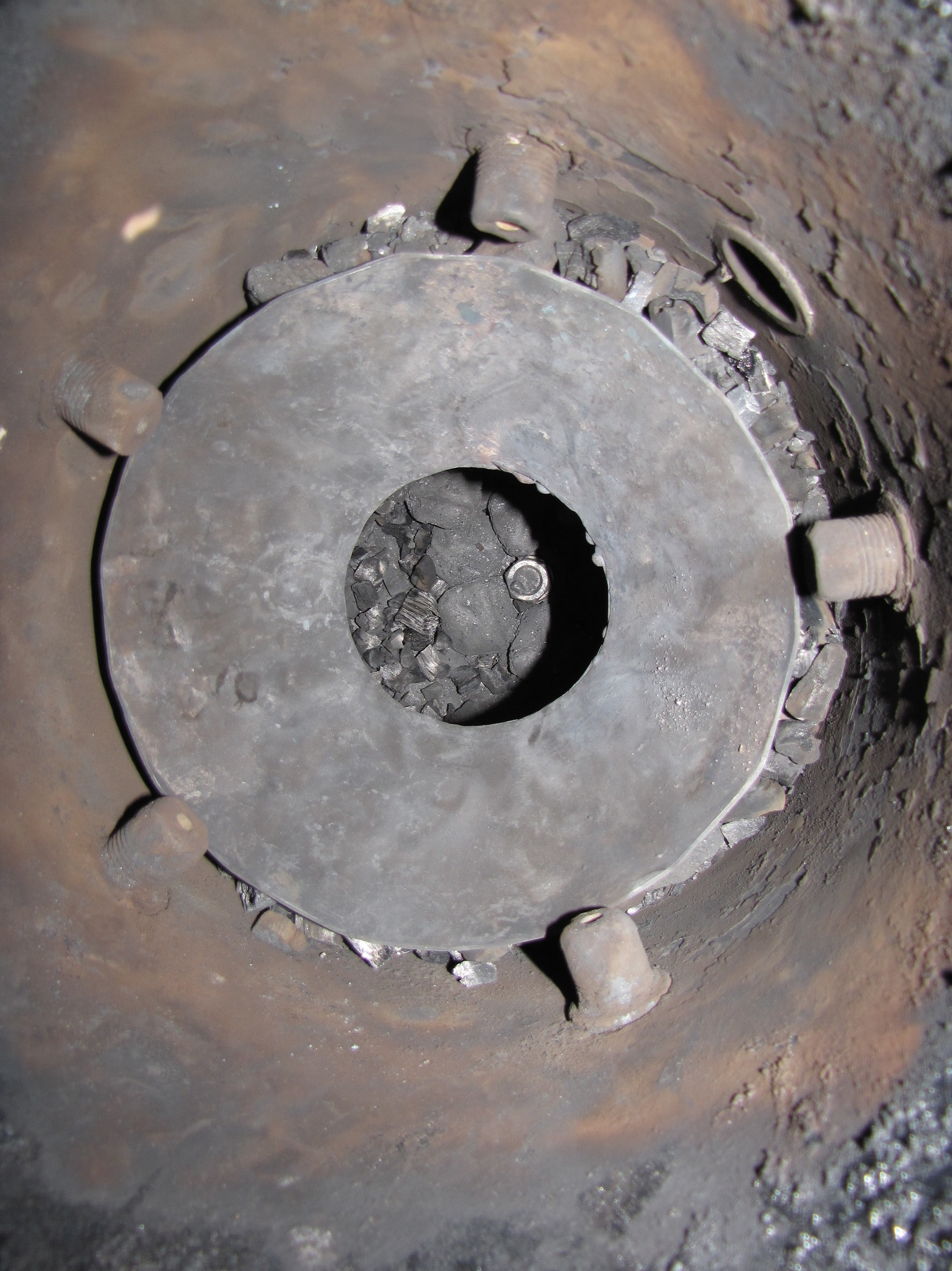
Note on comment 445 above on the through the shell ignition port in comment 270, that part 4 is shown welded and not engaged in part 2. This was done for clarity, but may be confusing anyway. Part 4 should be fully engaged in part 2 BEFORE welding to part 3. This insures an airtight fit when the pieces are screwed together.
I like it pepe that’s what I was thinking also more preheat I just picked up the brass fittings ouch there went 100+ bucks but all for good. but this design should come apart for cleaning.
When I saw your unit a few days back those gas fittings jumped right out at me. Copper, yea. There, somebody else is trying it. I have only 1 season or so of any temp records, so not much to compare to. However, hotter is better I would say. I agree with the take apart for cleaning . The lesson is start temp monitoring from the beginning. I’m approaching the 100 ouch mark. Can’t wait to start cutting and fabricating and the ouch will all go away. I’ll be into it after Easter.
Hi Brian,
I meant I spent 100 bucks, too. Once I get my mod done, the pain of spending a c-note will disappear with a smile. I was just trying to be funny with words.
Pepe
were you able to get your jig made pepe my parts didn’t come till late in the day so no progress here it supposed to be a little warmer here tomorrow it helps the motivation