Giorgio, here I will very much agree with Kristjan’s opinion, my theory is even that it is necessary to strongly preheat the incoming air (preferably to a temperature higher than 600°C), thus the overheated air increases its volume 3 times and thus the overheated air has a 3 times higher speed through the nozzle, the flow becomes turbulent, which enables better heat transfer from the metal, the air flow penetrates deeper between the coals, and what is most important, all the heat energy is returned to the gasification process, my idea is that in this way we get much better gas and much lower temperature at the nozzle.
9 Likes
thermosyphon heating would look like this, let me say that the basis for the circulation is the cooling of hot water, where the water becomes cold and heavy, thus pressing down and displacing the hot, lighter water let me add that the radiator should be narrow and tall, like the one Marcus made for Toyota
7 Likes
I don’t think you would need a radiator at all. You are just trying to keep the nozzle below melting temps and it’s probably going to flash to steam before it thermosyphons anyway. I think just a reservoir open to the atmosphere would be sufficient.
6 Likes
Im with Tom here. From what l know thermosyphon dont like bubbles.
And if the steam is used in the gasifier even better. In that case l got nothing aginst it. The water needs to boil anyway.
7 Likes
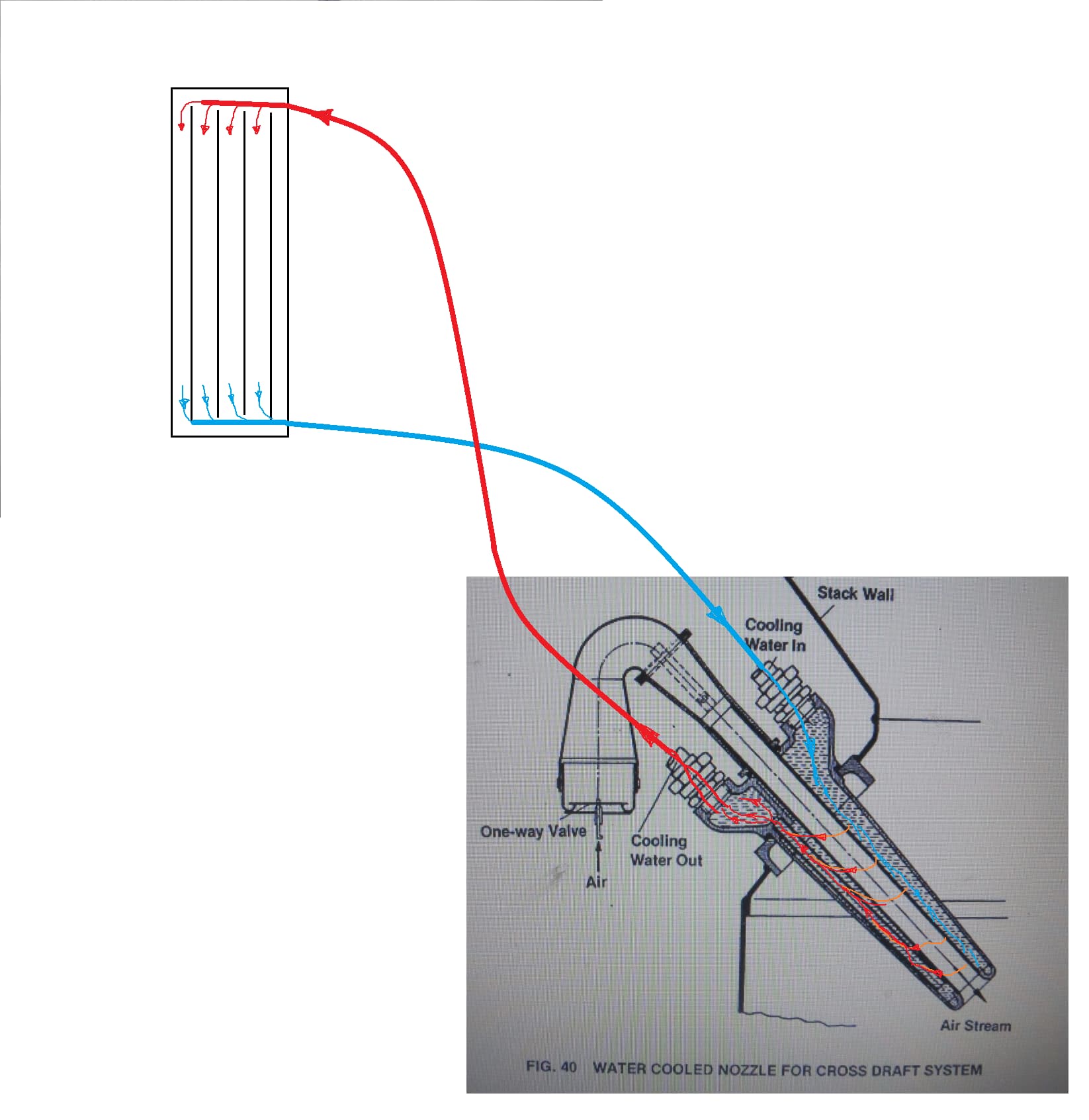
Water and steam, this is always an interesting topic, if you observe a container of water that you place on the stove, at first the water circulates slowly and heats up quietly, but when it reaches a temperature of approx. 80°C, a noise appears and the water warns that it will soon boiled. What exactly is this noise? Down at the bottom, where we heat the vessel, mini-bubbles of steam appear, which rise and the next moment cool down in contact with cooler water, it sounds like mini implosions, well, on large steam lines and condensation lines, this phenomenon is so strong that it can ruptures pipelines. If you look carefully at the picture of this nozzle, you will notice a narrowing in front of the exit of the cooling water, the designer probably forced the water and the steam bubbles to exchange heat in this way, so that the steam bubbles liquefied again.
6 Likes
This implosion effect can be incredibly strong. At work we had titanium ore disolvers, big 100m3 vessels heated with steam. The amount of underground concrete fundation for each one was insane. Yet still, when steam was injected in the slury, sometimes the whole factory wuld shake like an earthquake.
10 Likes
Hey Giorgio,
I think, for thermo syphon flow, the inlet and outlet are reversed in that image. I’d say there should be as direct a path as possible for the hot water to rise for best flow. I doubt the orientation matters if forced circulation is used.
I’ve used thermo syphon nozzles that are almost completely horizontal without problems. Even very long ones with lots of heat exchange surface.

On the heat loading issue (how much heat the liquid cooled nozzle absorbs), it appears to be determined by two things;
*the surface area of the nozzle exposed to the hot zone, or, how blunt the end of the nozzle is (make it sharp to limit the heat absorbed)
*the velocity of the air. Counter intuitively (to me anyway), high velocity air seems to reduce the heat load on the nozzle as it moves the hottest zone away from it.
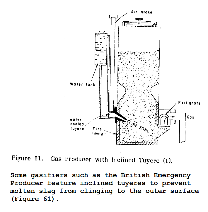
The downward angle seems to be about limiting slag buildup, not promoting coolant flow. I think it was the British pattern design that mentioned that. I’ll see if I can find the reference. It has been true in my experience that the slag puddle of a nozzle sized for high velocity, and angled downward, stays clear of the opening.
TNSTAFL, but, I like the complete confidence you get with liquid cooling. You never have to worry about your nozzle again, no matter how hard you work it. Yes, you now have to worry about your cooling system:)
Divided flow:
I doubt it is very important, but there is some divide in my nozzles as the outer tube is compressed to meet the inner tube at the flange. This is only effective for a short distance as they soon become two concentric tubes further from the flange.

5 Likes
On liquid cooling and steam;
I’ve never had a nozzle act as a boiler, except once;
I was using forced flow cooling from a hose and I forgot to turn it on before startup. I figured I’d melted the nozzle but I turned the hose on anyway. It acted as a flash boiler for a few seconds, shooting water and steam, but it calmed down immediately. The nozzle was fine.
I’ve never had it actually boil, even with the most blunt nozzle.
With that fully flat faced nozzle, using thermo syphon flow, you could hear the “nucleate boiling” a little and the circulation was more vigorous, and it heated the reservoir pretty quickly, but I’ve never had it actually produce steam.
Even when running pressurized (no engine) to create massive flares to impress the relatives.
My conclusion is that liquid cooling is very effective and very easy to achieve.
8 Likes
thanks chuck for detailed answers and sharing your knowledge, always very interesting to learn from the experts here…
ciao giorgio
6 Likes
You are welcome Giorgio, but make sure I’m not in the ‘expert’ category Lol! I’ll gladly share my experiences but my conclusions may be totally off. I’m sure you have an expression like ‘free advice is worth what you paid for it’. ![]()
On coolant flow and steam bubbles;
While I’ve haven’t observed actual steam production in the liquid cooled nozzles, I think it might be more accurate to think of the coolant flow as a ‘natural circulation boiler’ rather than ‘thermo syphon’.
Natural circulation boilers rely on vertical flow paths from the hottest zones to cause the liquid to flow. This is combined with a relatively tall vertical column as Tone mentioned, and a low restriction ‘cold’ return path.
The critical difference is that steam bubbles actually increase the flow instead of disrupting it.
8 Likes
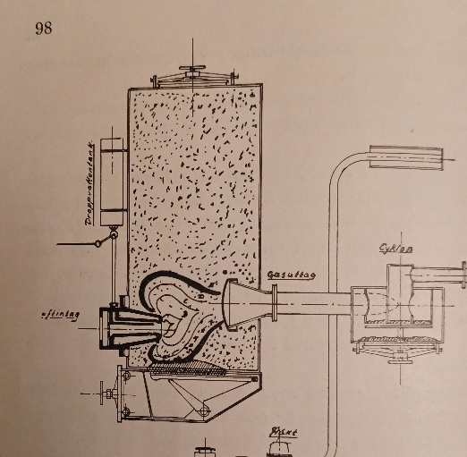
Could someone explain the gasifier in the picture. What is the purpose of the hour glass hopper and what is the grate supposed to do so far from the nozzle and hot zone?
Your real world experiences with water cooled nozzles and reporting on them is more valuable than endless speculation or second or third hand regurgitating could ever be Chuck. Thanks.
6 Likes
My working with a single nozzle on my “Charcoal Gasifier That Wanted To Be” was this. Right in front of the nozzle is where the charcoal is used up and turned into ashes, causes a void that is filled from above. So this will use up the charcoal on one side of the hopper where the nozzle is located. So the other side does not go down. The cone shap above helps to cause the charcoal to flow down evenly and still filling the void in front of the nozzle. A round barrel shape hopper with the cone in it is the best. But a square shape hopper will work too with a square shape cone. I think @don_mannes made one fore his gasifier.
Bob
6 Likes
Hi Chuck.
what volume of water should be provided to protect a nozzle? Is it necessary to put water back into the tank frequently?
3 Likes
I don’t know the actual volume flow… but you can see a worst case example in the last few seconds of this blurry video.
This was an early test with the flat faced nozzle, using total loss cooling from a garden hose. If I were guessing I say it’s a half a gallon an hour max.
https://youtu.be/BUQFCkW2UU4
Here is another test using a similar flat faced nozzle but with a cooling tank of a few gallons. This tank with a flat faced nozzle would get pretty hot and evaporate down to the circulation hose in six or eight hours.
https://www.youtube.com/watch?v=D3KtkhBHFAs
I did a total loss/garden hose setup on a recent nozzle and the flow is truly miniscule, half of the flat faced nozzle.
I’ve used an open top sixteen gallon drum which will go for forty hours or more before needing topped up. I’ve used a fifty five gallon drum and I never noticed it dropping (but I’m sure it eventually would).
I always planned to build a radiator setup for using the liquid cooled nozzle on mobile gasifiers, but I haven’t gotten to it yet. I have all the parts to emulate an automotive radiator with a pressure cap header tank and siphon reservoir… it’s on the list:)
5 Likes
THANKS Andrew, for posting your modified simple fire NOZZLE, COULD i get a clear picture of the inside of the can with the Nozzle showing in its running location, or a drawing of this charco gasifier and nozzle layout.I want too build a simple fire for test in pontiac vibe 1.8 motor. I have hard time finding the whole layout of the simple fire gasifier. HOW IS THAT ALUMINUM nozzle lasting in HOURS so far,THANKS
3 Likes
Hi Chuck
in my opinion only 4m3
.212 liter x( 3600/2)x60x.5x.5x.7=4m3
maybe I apologize too much!
2 Likes
Could be, always check my numbers for sure!![]()
Here’s what I did;
Displacement=.212L
Rpm=3600
Four stroke so half the down strokes are intake (RPM/2)
Gas/Air mix is about 1:1, so gas is 50% of intake volume
Only about 70% of the displacement gets filled on the intake stroke (Volumetric Efficiency)
60 minutes in an hour
This gives;
.212x(3600/2)x.7x.5x60=8014 cubic liters, which converts to about 8m3 of gas an hour?
I suspect the volumetric efficiency is lower than 70%, possibly as low as 50% depending on system drag. The engine has to draw through a nozzle, through a fuel bed, through filters, and a restrictive carb, in addition to any negative Kadency effects.
The fuel air mix isn’t exactly 50%, which depends on chemical makeup of the gas.
There is often water vapor dilution in char gas.
All to say, none of this is exact.
4 Likes
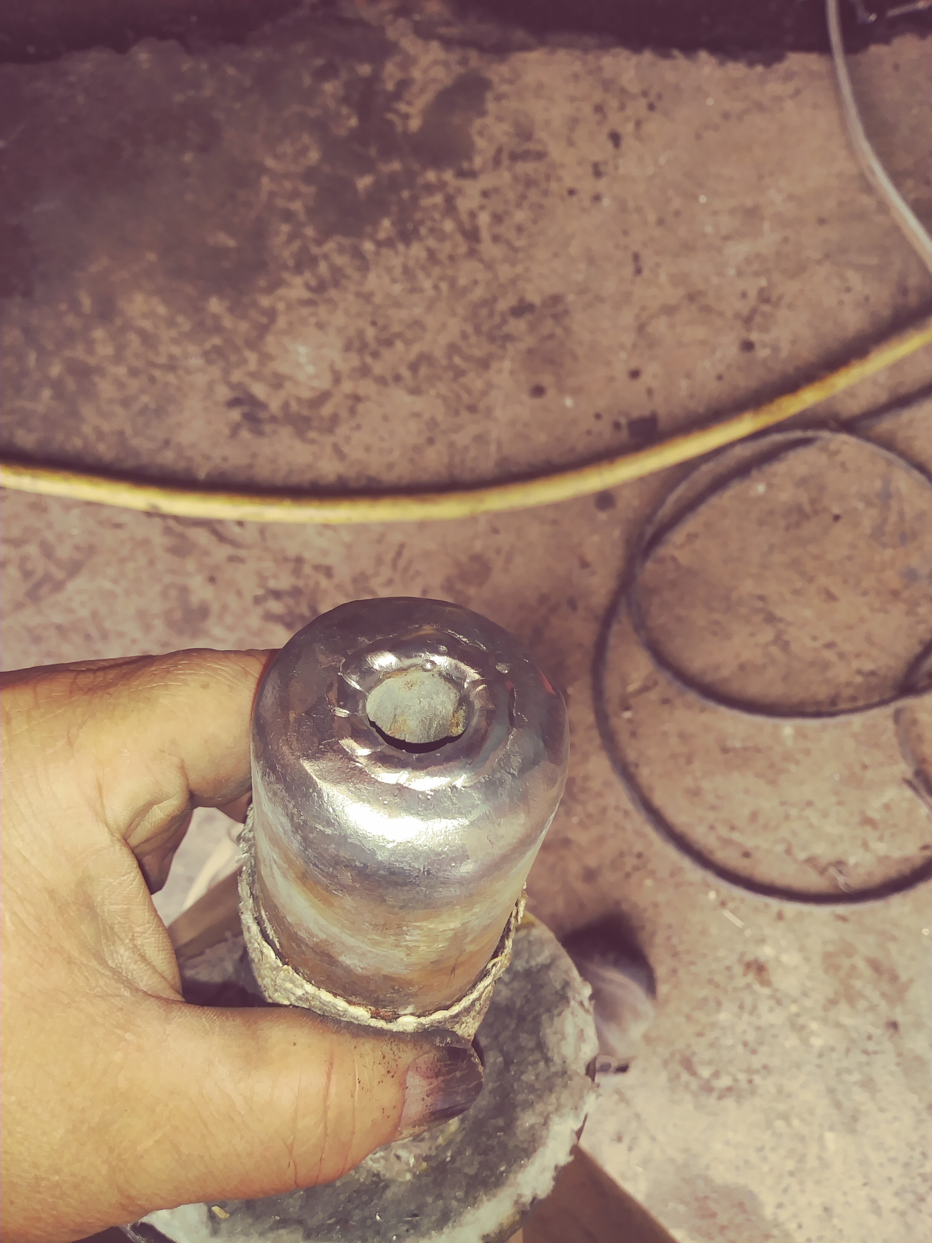
As i promised, some (bad) pic’s of water-cooled nozzle set-ups.
First of all, i agree with Kristijan and Tone, wasted energy to cool the process, but should be a cheap and easy way to make a “forever-lasting” nozzle? Also what Chuck states, i think it’s good to lead away just enough heat to save the nozzle, by not let the water all the way to the nozzle tip?

Volvo cross-draft, for trucks, 16 is coolant pipes.
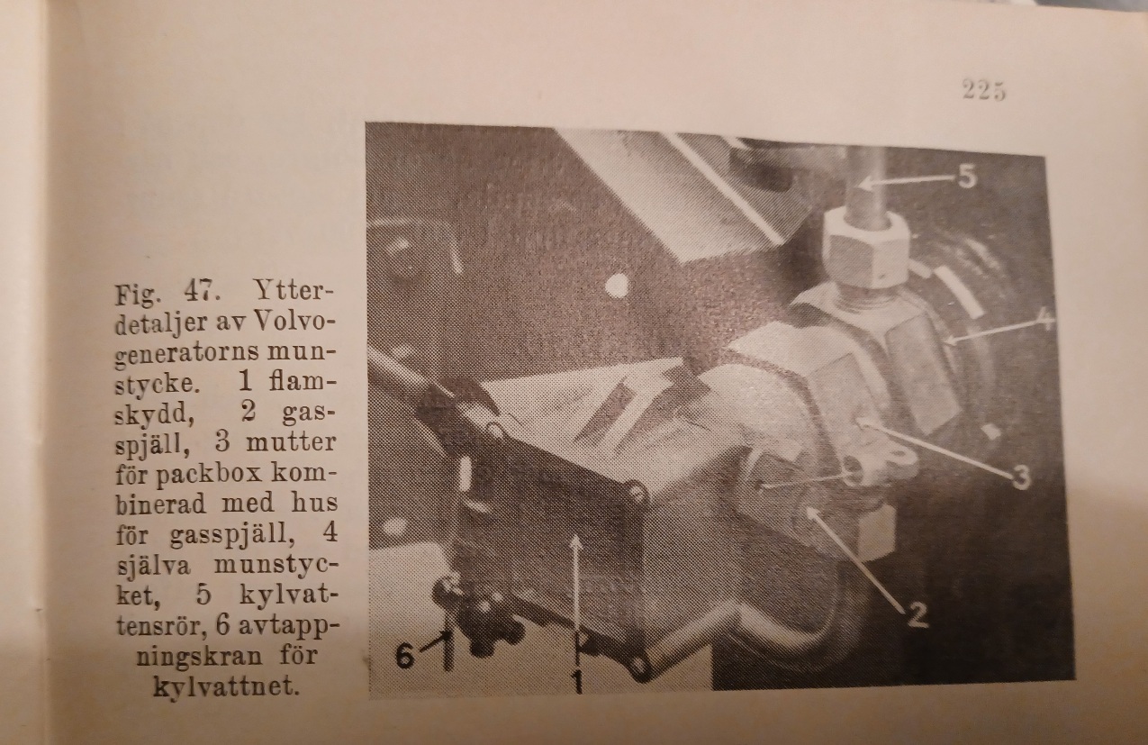
Photo of Volvo’s air-intake, 6 is drain valve.
Combined with spark/flame arrestor, and shut-off valve.

HSG (High-speed-gas) British construction,
No cooling pipes or radiator visible, 16 is drip-water container.
Interesting is this gasifier is “grateless” the “trap-door” bottom is for easy emptying. (It should be emptied before every start-up)

Prototype for Volvos one-wheel cart gasifier, the narrow, square container is the coolant tank/cooler, (mounted beside hopper)
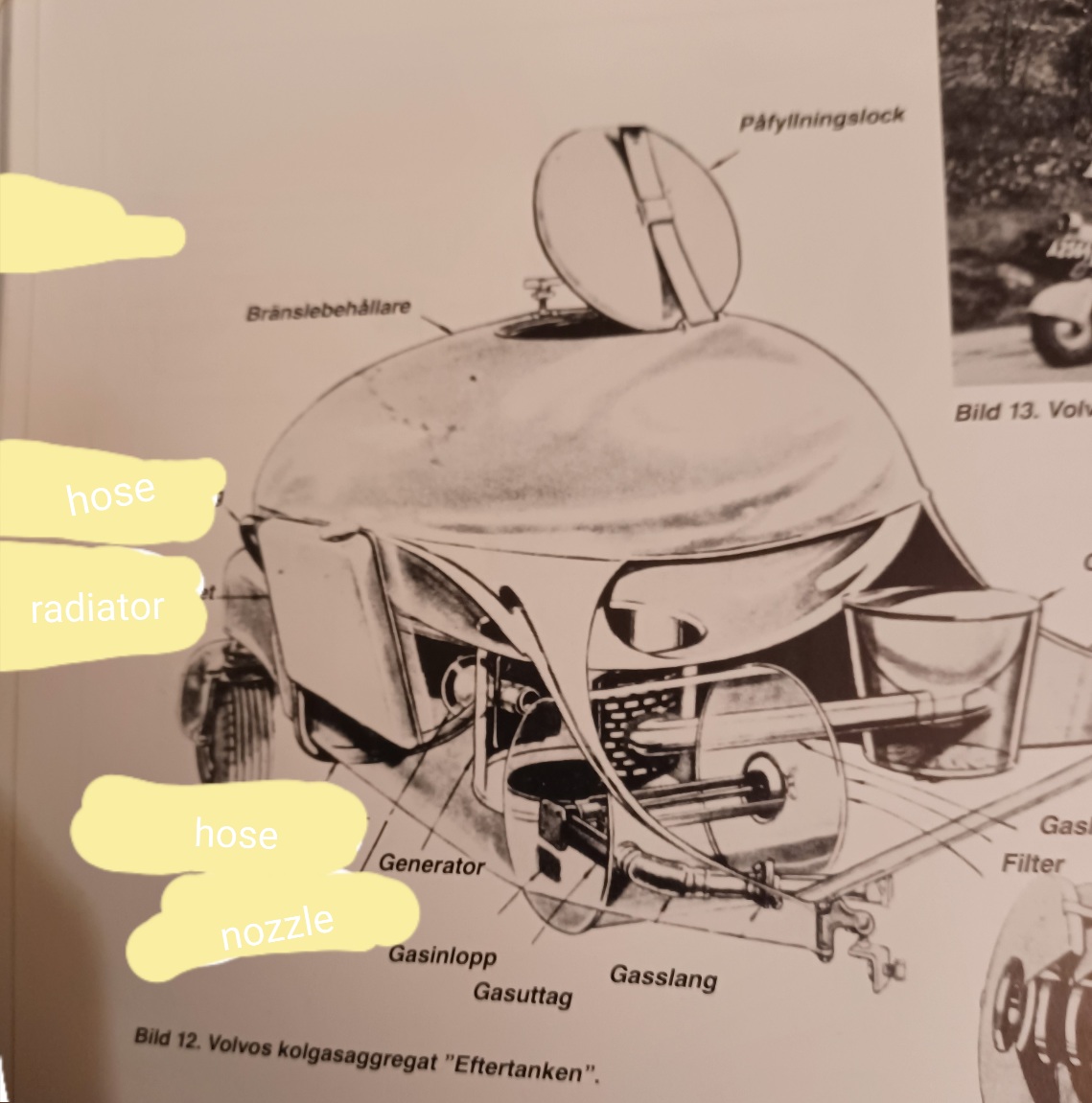
Advertising/exploded wiew of Volvo’s one-wheel cart.
HSG-Greener.
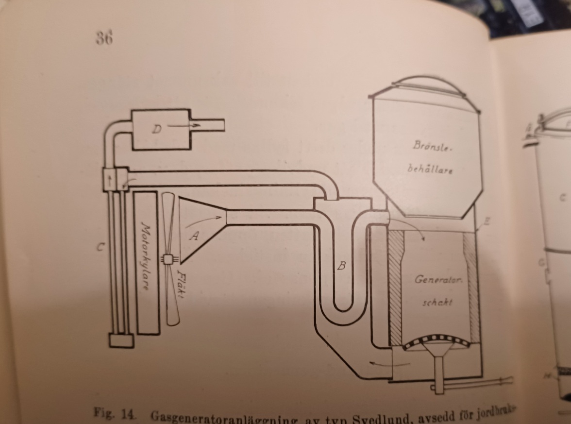
Bonus pic, Svedlund pre-war (1928) tractor gasifier, nozzle-less, almost like a FEMA, a “funnel” catches air from radiator fan, for start-up, and as a attempt to “supercharge” it some.
And notice the drop-box, heat exchanger, like a predecessor to the WK?

Bonus pic 2, Widegren brothers gasifier, same air-catcher as Svedlunds (probably copied, this one showed up 1933)
C, is a slot to let air in, the hearth (ceramic) is round inside, the housing/hopper is square.
What i found interesting is in the manual it recomends to mix the charcoal with 15-25% very dry woodchips, to increase the power, and save charcoal.
9 Likes
LOTS of charco gasifier pics, and good nozle cooling ideas too try.,Thanks for posting. are there any good books for building charco gasifiers- updated tested designs for small cars. I would like too buy a GOOD charco gasifier building BOOK, NO VIDIO needed too get the full picture.
4 Likes