Tom, Tar fences are for correcting mistakes. I ran the full gambit on them … My current experiment is using copper tubing for nozzles … I have 8, 3/8 OD, 5/16 ID at 4" long. They end just at the brake drum in the rotor. They are not in the hot char zone and always have somewhat cool air going through them like 600 degrees F… I coated over them with furnace cement and cured that and then there is ash and now lots of wood goo … So far so good. The last few test runs pulling around 5" of vacuum on the system and using a hopper full of chunks each time yielded nothing but ash in the cyclone and the condensate was clear from the cooler. I’m concerned at the lack of slipped char. I may have an air leak in the gasifier base and it is burning up. Time will tell when I start driving with it. I can’t afford any stuck valves with this truck. It flares clear out around 4 to 5 feet … Just clear ripples but I can light a napkin in it and it is burning the grass and leaves under it … Maybe I should do it at night some time … I’m waiting on some expensive flex tube to show up … Mike
tom don’t take this the wrong way most of the people on here I believe have put time in a system or two I did .it sounds like your set up just isn’t what your looking for rather than beating your self up do like you mentioned run your unit start another [ w/k ] on the side it will take no where 14 years and use the old unit for yard art . I m glade I through in the towel regrouped and started over done loving it . as for copying someone every body on any site is some way or another copying somebody from now to 100 years ago so don’t be so hard on yourself paul.
Hi, Tom!
First, I am surprised and astonished to hear, that talk of a tarfence; in your picture of the hearth there seems to be no tarfence cylinder rising up towards the nozzles, and I have had no reason to talk about it in this conversation, so far…
Vesa Mikkonen’s measures seem to belong to peat gasification; there is a modest blast not to melt peat ash. For the same reason the imaginary velocities are kept lower in all passages.
As you have 5 nozzles now, the logic of increasing upper hearth temperatures fits well with 10 nozzles, but for tennis-ball to egg wood-size do not shorten the current measure!
All 10 in the same current plane.
Then the 10 nozzle SHAFTS can be 1/2" INSIDE, but the “trumpeted” nozzle-tips internal diameter = 6.75 mm = 0.2657"
So, if you want the equal blasting velocity with other factors equal…
A cylindrical plate from the inner rim edge down to the lower brake drum “flange” filled with ash from the upper hearth (after opening the route) can be a stable and free insulation as an alternative to winding insulation around the lower drum.
A perhaps more stable alternative for round grate-bars is self protecting angle bars.
Max
Good evening friends; Paul—I take after my mother. If she had to bake a cake for an event, she could open a Pillsbury cake mix. But, she didn’t. She went to here receipt box and pulled out receipt she had acquire from and individual. Something about, when receiving a compliment on the cake, she would loose some of the pride by having to say, " it’s a Pillsbury mix".
Max; I am posting pictures with and with out the tar fence — which is what I have been using. I would appreciate your thoughts about this and with the long nozzles, will char fill in the area? I’m surprised to hear you say that Vesa’s design is for “peat moss”. Steve U. just grouped Vesa’s and WK design being similar-- yes, in using a slow flowing gas. WK is proving to be very successful so I was considering the Vesa dimensions as I thought the slow velocity would be good. Your suggestion of having 10 nozzles at the present height above the restriction sounds like a good possible chang. And, the 1/4 in. nozzle opening fits-- if I double the number of nozzles then about 1/2 the nozzle diameter makes sense. I like the idea of a insulation cylinder from the lower rim to the brake drum. I would have to cut slots in the upper brake disk to let ash go down into the cylinder. How about if I just drill a hole in that disk and use the hole to fill the area with sand? What do you mean by “self protecting angle bars” for a grate?TomC


Tar fence, and the rest…
Hi, Tom!
I am glad to have arranged two parallel monitors; the cursor can move back and forth between them. On one writing comments, while reading and looking on drawings, pictures on the other.
Easier to keep thoughts? together…
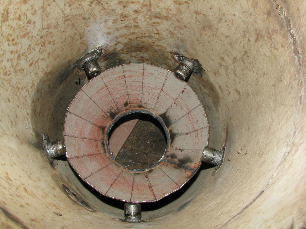
Looking at your two pictures: On the upper one there is an extension ring upward on the brake drum cylinder.
But, o dear, it is tightly following the hearth wall, so how is it “fencing” between one SIDE and the other against pyrolysis gases ???
IF you had nozzles screwed in their places, their tips would be reaching long inside the “fence”… impossible to determine more than one hole for nozzles? At 11 o’clock…
On the lower picture there are nozzles, but seemingly screwed into a cylindrical wall having a much wider diameter.
Better to say no more, until revealing pictures tell the story…
OOPS!
By enlargeing the pictures to ORIGINAL size, they reveal that the “hearthwall” is the tarfence!
Bending the upper edge outward covered the “truth” about it.
This bent out collar and the “injector” holes below it, will suck pyrolysis gases from the outskirts of the pyrolysis zone just above.
On the other hand, it will take some time to collect small char and ash outside the tarfence to provide the needed insulation.
If the route around the collar edge gets too cold, there will be tar condensation and clogging. You may need to decrease the outer diameter of the collar to avoid that…
…
Imaginary velocity alone does not determine the construction-type of a hearth!
In a WK, the fuel bed is moving “cylindrically” down in the upper parts of the tube, until it meets the ash-cone, held up by the restriction ring.
While moving down “cylindrically”, it gives off lots of heat which is MANDATORILY taken care of by the primary air preheating on the outside.
…
In an Imbert type the ash-cone is reaching up to the tips of the blasting nozzles, and depending on the internal proportions, the heart wall is usually “out of risk” to be burned.
On the other hand, with overly big (and cold) hearth diameters compared to the active region, there is a risk to get “sneaky” tar gas in from the sides to and through the restriction, before the ash cone coakes and hardens, which can take ~50 hours.
As a starting remedy against this, the “tarfence” has seen the light of the day in the beginning of this century. Jim Mason gave it the characteristic name.
…
You shall remember, that Vesa Mikkonen began his woodgas history solely and only on peat gasing; it is more energy concentrated than wood per weight unit! But the ash melts at a much lower temperature than the ash of wood.
It is only in later years he has turned to wood, because of availability.
It is a remarkable difference between dimensioning for peat and wood!
Not everybody notices the differencies…
…
Don’t make shortcuts with nozzle measures!
Diameters and areas do not go on a linear scale, there is squaring involved, so calculating according to rules keeps one on track.
Rounding values, especially when small and 10-folding will go down the slopes!
0.2657"!!!
…
Angle irons collect protecting ash in the “ditch” and radiate freely on the down-side; thats why they last.
Don’t weld anything under them in the middle part.
Max
And keep it for a spare BECAUSE YOU KNOW HOW TO MAKE IT WORK , and or run a gas welder with it and start a totaly new project with all your new KNOLLEGE.would be much easy’er, 40 hours or so, some heavyer tube, finns and or air channel, you could use your existing hopper. build new below hopper. JUST A VEIW POINT. I still gotta build a decent ash box heat exchanger.
Good Morning TomC
I did set many known systems into TWO different broad groups based on there differenrt approaches to internal active material volumns and internal velosities. The Vesa ststem and the WK are in completely diffiernet groups! Plaese re-read. Maxgasman too for his diffnert expalaination saying the same. His highlighting too of Mr Vesa’s design for peat/sod fuels.
These two broad grouping I see up are atcually mid-range of extreme possibilities.
Plasma gasification at the far quickest-time, highest velocity, lowest volumn of metered in material end of things.
Larry Dobsons works at the other extreme of largest active material volumn, with the slowest velocity and longest residence times possible.
These extreme approches are proving very containent materials difficult to build practical useable for.
Another split possibility of use groupings is grating approaches:
GAS and ASH flow through the grate holes or slots as in true Imbert, VesaM’s, early GEK’s, SMP’s, Fluidyns and VACOLA and their varients.
GAS flow out and off the grate edges. With primarily only the ash intended to down through the grate holes/slots flow/drop. By-Pass grating as in the WK, most all Victories, LeRosafiers, and many, many others.
As you can see these diffenrt grateing approached span the hearth types.
Then the grate-less approche as in DASAGIIscMukundas, 3G-I’s, all fluidized beds and some others.
As Max says the ash contnent and it’s melting/slagging point will be THE actual driving in your grating choice. Then a choice for maitanence intervals. Choice to maximimize all char as internal to be as fully as possible used up for solids to gasses engine fuels. ME!!
Or maximized “preserved” for later out of gasifier other uses like activated charcoal, or use in a charcoal gasifier.
You can actually stand aside figure a guys phlisophy and goals from these design choices he makes.
Regards
Steve Unruh
Hi Tom,
I’m just catching up on my reading and see you’re a busy man. I’m not sure if you got back to my site so I thought I’d add some info on my cyclone here. Also added my latest burner version and a few pics of the cone above the grate. On this version chart I compare the theoretical numbers with the “as close as I could get with what I had” materials. Note that these are Imbert line D dimensions. They’re pretty close and I’m making good gas. The cone keeps the gas in the hot char for a long (relatively) residence time. My finished gas is almost colorless as can be seen in my youtube posts. The space between the firetube and cone gets filled with insulating ash to keep the char as hot as possible as long as possible. The inlet air tubes (and air) are further heated by the exhaust gases. My nozzles are 1/4" dia as suggested to me by SU way back when.
I chose Imbert because I want a stand alone unit for generating elec. Line L could theoretically run a 115 HP engine.
Pepe


Bad news. While I drank my coffee this AM the ground went from green grass to pure white "snow’. 12 inches by tomorrow morning and the highs for the week at freezing.
I wanted to fill my gasifier up one more time before I tore it down, to see if I could find why it ran so badly the last time out. Now we could get a few days of “indian summer” after this storm or not (?). What to do.
Right now I want to thank all who have taken part in trying to improve my design,Max,Wayne,Steve U, Patrick, Mike,Kevin, and most recent Pepe. You have all given me much to think about. Some of the things that have stuck and I am sure I will do are 1) Protect the heat that I am making. I’m stuck on the idea of a “tar fence” but I plan on making it just the “fence” part and removing the “horizontal” portion of my “fence”. Then I will back fill the fence with packed ash. Then from the restriction down, I want to put a container around the brake drums and fill that with ash also. Pepe’s hour glass holds the ash insulation all in one. That ceramic insulation turned out to be a little pricey. 2) I “think” my nozzles are ok, but, I guess I will increase the number from 5 to 10 and that will mean new tyre (?) inside diameters. I have a draw full of restrictors I use in the 5 nozzles that I used to get to what I have. 3) the grate. Again I “think” my rebar design is OK. If it hadn’t been for the extreme temperatures I got on the last run, it had worked well. So, I see the benefit of Max’s angle iron bars for cooling, but don’t think I need that. Steve U. What were you referring to on the grate when you said, “Me” in your last post. Max talks a lot about “ash” which I see very little of when cleaning out the “ash”. Mine is mostly small marble sized charcoal. When reading the posts under “charcoal”, I see my “marbles” as a lot of lost gas. Besides grate configuration, I would consider increasing the distance to the grate ( a major project, but do-able)
Anything else you can think of I will appreciate your comments. The “changing” process has not started yet so “nothing” is for sure yetTomC
Hi, Tom!
Every expression of intent or speculation of process properties is a step forward.
- Have you had any kind of (tar)clogging on or under the horizontal part of the fence?
The part above the nozzles is aggravating the “production” of ash to fill the space between the hearth-wall and the “tarfence”.
The additional or original intent with the tarfence is to prevent “back-sneaking” of targas between the nozzles through the fresh char to the restriction and further.
About 50 hours of use will tar-coak the char-cone, so after every total cleaning the tarfence is a good firsthand protector for the motor.
-
You can well use 10 nozzles with ½" “shafts” and 1/4" tips, but do not change the total length. The tips themselves, should not be longer than ½", to achieve the best blast with the least preasure drop.
-
Round grate-bars cannot radiate much more heat than their “naked” upper half is receiving!
Ash, soot and mini-char is collected stationary in and on the ditch of an angle-bar, protecting it from radiation and convection from the passing gas and slipping particles.
The lower side has a greater surface than a corresponding rebar has.
This gives it a clear advantage to radiate more than it receives, and therefore staying cooler and more longlived.
Ash is very much hidden in soot…
In charcoal gasification, most “small marbles” are removed beforehand…
and new ones bound 'till they are gasified in the mass. They are seldom pushed downward by DOWNDRAFT!
Pushing down the grate invites more ash clogging to be countered by more mechanical activity…
Personally, I would decrease the diameter of the reduction zone, but keep it well insulated by passive ash separated by a cylinder between the restriction-plane and a tight own bottomring. The (narrower) grate would then sit just under the new bottom ring between the heart tube and the new cylinder.
The new cylinder would have an open edge just under the restriction plane, so the cylindrical “cavity” will always be well filled with, you guessed, ash.
Max
Pepe; Here are a couple of pictures of one of my earlier builds which in ways is similar to yours. I have always worked on a gasifier for a 4.3L engine so in any build I have stuck with the same basic dimensions-- which I find close to yours. For me this design had several problems and rather than attack them (because of a lack of basic knowledge) I went on to build a new one. I totally gummed up my engine twice breaking push rods. For me, this design ran “cold”, made a lot of tar, and condensate which ran up to the engine because my piping went down the roof of the car.
The first picture is the basic chamber showing the pre-heat tubes ( molded after the GEK before Mason came up with the name GEK) The second is the chamber being placed into the outside chamber.


You been a hard working guy trying too get good motor fuel. that was my fear till i found the wayne keith DOW web site. what a blessing it is.I know its going to save me a real lot of time, material.money, motor gas. Good luck on your update builds or new builds.
Again Thanks Max; Sorry I didn’t get to talk to you in the “hangout” last week. I think I have a problem with my external speakers. Then the conversation got quite deep in a commercial program so I bailed out. Besides it would have been impolite for me to just talk to you with the others sitting there.
Ok Got you last reply; 1) I have not had any signs of “tar” on or around my tar fence. I agree the horizontal part of my fence stops ash from forming and insulating the area. That is why I will remove the horizontal portion and pack ash behind the fence up to and covering the protruding part of the nozzles out to but not the ends. I don’t want to run the gasifier with out filling in that space because as you said the purpose is to keep tar from sneaking around the nozzles.
-
I will go to 10 nozzles of 1/2 inch tubing and make up inserts of about 1/2 inch long and a 1/4 inch hole. I agree the inserts should be long enough to create a laminar flow but short enough to not cause a back pressure I plan to keep all basic dimensions the same as in the past-- nozzle circle, distance from nozzles to restriction, and restriction.
-
You mentioned making the diameter of the reduction zone smaller. Hmmm How about if I put a cylinder “inside” the lower brake drum down to the height of the bottom rotor disk, with a inside diameter just a little larger than my restriction. Not sure how to put a slot in the top that can catch ash if I stay slightly larger the the restriction. I can of course buy some insurance by filling this area initially with ash. I will have to have a bottom that goes from the cylinder to the brake rotor to hold the ash in. Oh, and how thick would this new cylinder have to be? Are we getting into the heat range of the WK where they are having some problems, even with 5/16 thick tubing?
And then there is the grate. I will need to make a ring ( maybe out of rebar) and weld the angle iron strips to it. I’m thinking that if I go to a “reduction” zone of about 5 inches, this is going to be a very small grate (about a 5 inch diam ring) and the angle iron will have to be about 1/2 x1/2. That would probably be about 4 or 5 bars at most and they would be very light gage metal. Is that what you have in mind??
Again thank you for you time and interest. TomC
Testing measures
Hi, Tom!
-
If the tarfence is tight welded in the lower end, it alone functions as expected; the ash around it serves as insulation.
-
Nitti-gritti details: Trumpet-rounding of the inlet end of the ½" X 1/4" will improve the flow. Outlet end, just straight cut.
If your current fuel size and “brand” does not crumble too much; decrease the nozzle-tip-circle from 9" to 8.5".
If your fuel size is between a tennis ball and egg size, then decrease the height between the nozzle-plane and restriction to 4".
And increase the restriction from 4.25" to 5.25" ; you need gas!
Insert an upside-down “cup” with new restriction opening and height.
The original restriction hole must also be increased, slightly larger than the insert(s), otherwise the new upper hole does not work.
- You are correct about the placing of the new cylinder;
just leave ½" between the cylinder upper end and the lower rotor. The ash and soot with mini-char will blow and splat into the cavity in no time.
Nothing hinders you to “prefill” it, if you take the effort; sure is sure!
Still, leave the ½" ring-opening for continuing topping!
If the upper hearth is measured right for your fuel and needs, then the reduction is the dominant process from the new restriction downwards. That means a sharp drop in temperature “just in time” for the new cylinder…
In the WK the heat inferno is in the upper region, from the “nozzles” downward to about the start of the ash-cone, where the reduction begins.
1/8" or next up will suffice until something else goes… take what you have.
The ring bottomplate welding to this cylinder is the bad point, if done as a straight “angle-weld”!
Either piece has to be rounded hammering glowing to meet the other “in the same plane” before welding together.
Otherwise the tensions or strains will break them loose from each other!
The inside diameter of the lower rotor sets the limit for the new cylinder diameter? Leaving an “ash-channel” to the cavity around the cylinder?
- The Grate.
If the grate is set just outside the new reduction tube, under the ring-plate-bottom, you have free’er hands with the horizontal dimensions.
I.E. You can perhaps bend (roll) a flat iron “frame” for the grate.
Making it 1–1½" high keeps it together, if respecting the “living” metal…
Edge upwards can be kept tight against the ring-bottom-plate… if needed.
Max
Hi Tom,
Thanks for the pics and comments. I’ve only run an 8 hp Tecumseh on my gas. I took the head off last week due to a backfiring issue. After 20 or so hours there was very little deposit on the piston and head. The valves were essentially clean. There was minor soot in the intake port and very little in the exhaust port. I take this as a sign that my gas quality is good so my internal temps should be good or good enough. This is the first time the head has been off this 20 yr old engine. The valve clearance on both was almost nil. I’ll reseat the valves then adjust (grind) valve clearances.
When I tear my unit down I’m going to lengthen the air tubes like yours are on an angle. I think I’ll put nineties in the fire tube and use flare fittings to connect with. Picking up a bit more preheat can’t hurt. I’m also going to install a thermocouple near the top of my hourglass hearth to get a handle on the internal temp. I may even put one in the grate area somewhere. Just off hand did you use copper tubing for the air pipes?
I made my grate as wide as the fall area of my cone by extending the line of the cone down to the grate. My grate has about a 12" diam and is 2" deep. It is about 4" below the bottom of the hearth.
Good luck tracking down the cool temps.
Pepe

http://jamclasses.drbanjo.com/static/dimages/IMG_4442.JPG
http://jamclasses.drbanjo.com/static/dimages/IMG_4446.JPG
Hi Tom,
Let me share my partial success/failure from my fluidyne days. First pic shows the rope gasket for the reduction plate and my small grate with an obstructive plate holding it to a rotatable shaft. This plate has a cool spot (relatively speaking) under it affecting gas production. The second pic shows 2 two other sources of leaks. The flange weld to the outer shell and the reduction tube weld to its mounting flange. I ran the 1/2" diam nozzles but couldn’t get a burnable gas with more than 2 of the 5 nozzles open. The combustion zone shifted towards the 2 nozzles and heated the shell red hot, see vid
The nozzles were changed to plugs drilled to 1/4" diam. Note reduction flange is gasketed and bolted in place. The third pic shows how the components stack up. Here is where one is tempted to experiment with “drop in” restrictions (reductions) and “hope” that the ash will seal it. Maybe yes, maybe no. Doubtful if the unit is constantly vibrating down the road jack hammering your ash. Ash, I said ash. I must say I have not recommended this method before and I stand by that. A pita to gasket and bolt for sure, but bad gas is a pita, too.
My Fluidyne trial made a burnable gas, mostly bright orange (some sort of chemical clue there, I’m sure), but also had some smoke and a moisture plume coming through the burning gas stream unchanged! Huh? Water… that’s from combustion, not reduction! The failure? I welded 2/3 of the reduction tube to the flange and only tack welded the other 1/3 (forgot to finish welding). LEAK. Some combustion products are by passing the reduction tube char bed and getting through unchanged, CO2 and H2O and showing up down stream. The larger grate ended up not being used here, but in my present unit.
Hope this is helpful. I’m not real familiar with the WK (sorry, Wayne), but a leak is no good anywhere, imho. I have a video of the burning gas stream and moisture plume I’ll try to post tomorrow and post a link for observation. Pepe


Tom,
Here’s the smoke and moisture plume video.

Pepe
Hi TomC
Just getting back on-line after a couple of power out days from a regional windstorm.
My “ME.” in my last post here was me saying like you that ALL of my woodchar in my gasifiers is to be used for motor fuel gas making.
With my relatively low carbon percent Douglas Fir fuel woods producing a very fragil woodchar I cannot fuel economy afford the current bio-char fantasizing.
Maxgasman is steering you straight with his advices for a small volumn, high velocity woodgas system.
Regards
Steve unruh
Hello Friends; Steve U glad you are back on line-- I am concerned that Max keeps talking about ash, and I am hoping “that” is what I will produce with his help.
Pepe, thanks for the videos. I looked back at some of my old pictures off my GEK style gasifier and the moisture plume in the flare looked just like your video. That was when I was getting moisture and tar up into the engine. Some day if time ever presents itself I should pull that gasifier out of the corner and try what you have to get it running.
And Max; You are giving me so much to digest. But after I read and re read your posts and get what you are saying and “how I can actually make the changes” I am putting them on my to do list. The weather has turned to full bore winter so my hopes of putting wood in my truck and taking it for one last run before taring it down is gone. Now a couple of question about your last post;
If the insulation cylinder I am going to put around the reduction aria is “not” welded at the top to the brake, leaving a 1/4" gap, but “is” welded to a ring at the bottom that goes from the cylinder to the bottom brake drum— do I have to round the cylinder/ring so they meet in the same plane?? I am concerned how I can do this. I probably would have to have the cylinder as flat stock and round the edge and then try to roll the stock into a cylinder. Any other thoughts on that?
The grate; If I take flat stock about 1 1/2" and roll it into a cylinder just a little larger than my insulation cylinder, and weld 1/2" angle iron on the bottom, with the open “face” of the angle up, what is the spacing of the angles. But more important, are you saying to mount the grate “solid” to the bottom brake drum. I will have no movement to shake ash through the opening and more concerning, I will have NO room for “slip char”. Is that what you are telling me. I like very much the idea, that this will make 100% ash but am afraid the system will get “constipated”, plugged up, if we get less than 100%. Can we keep enough heat on the grate to convert ALL of the char to ash??
I am just about done building a hutch for my daughter in law (who happens to be from Germany). And planned to get on with taking the gasifier apart, but last night when I got so cold in the shop, I went to build a fire and all my furnace pipes had rotted out. So now I’m headed out to try and rebuild the piping as without a little heat out there I’m a “couch potato” Thanks again every oneTomC
I’m sure glad you have a direction Tom. You’re in good hands.
I also would be interested in seeing a pic of the hutch you’re building