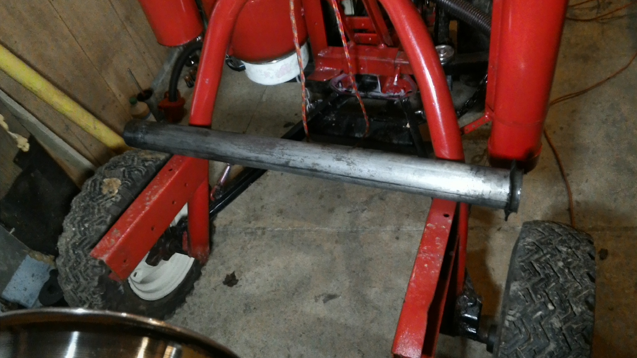
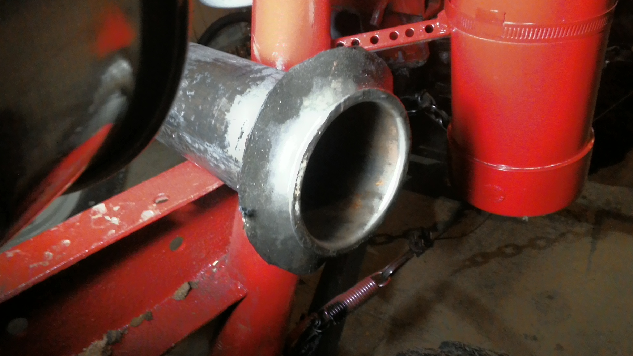
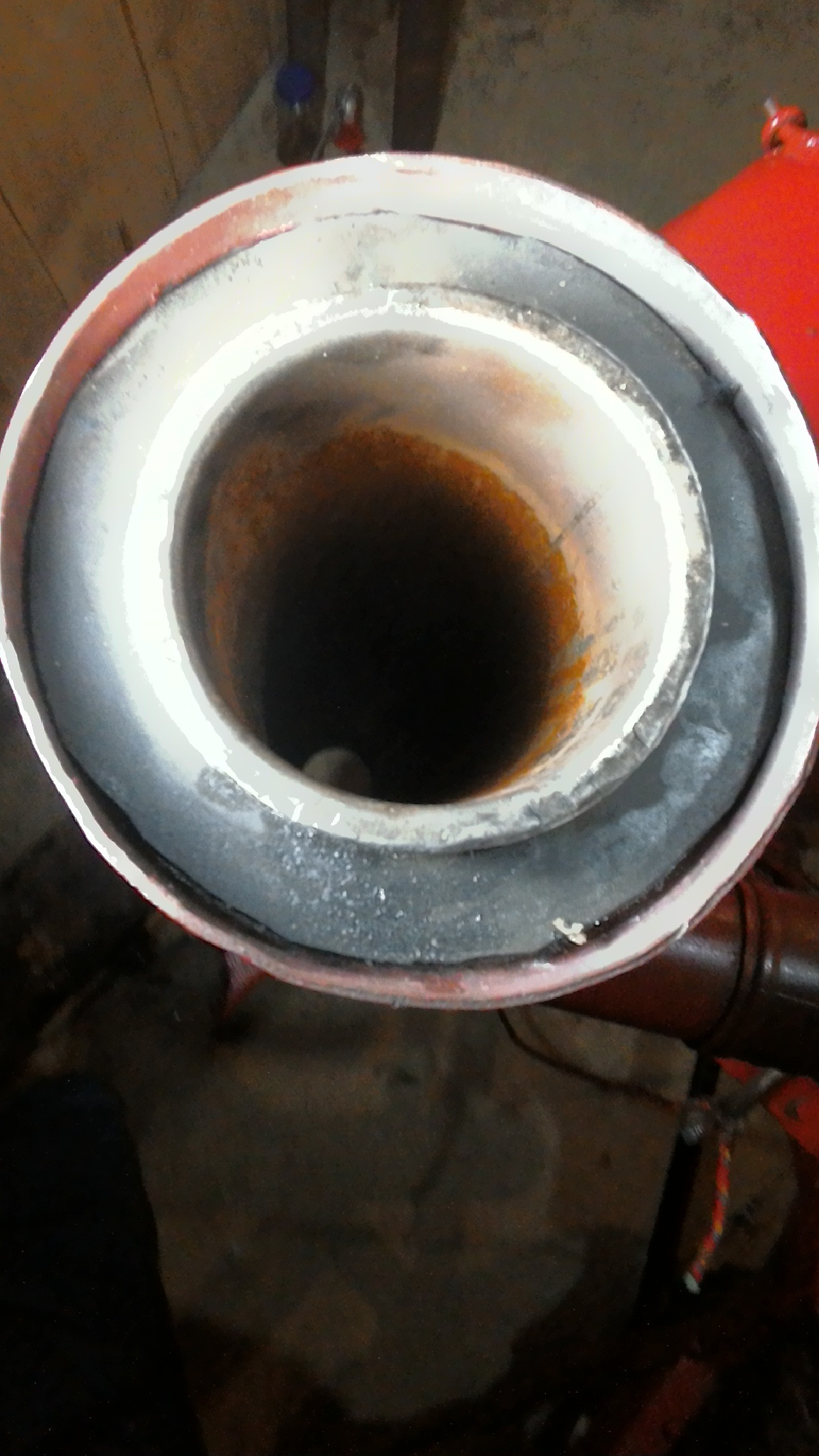
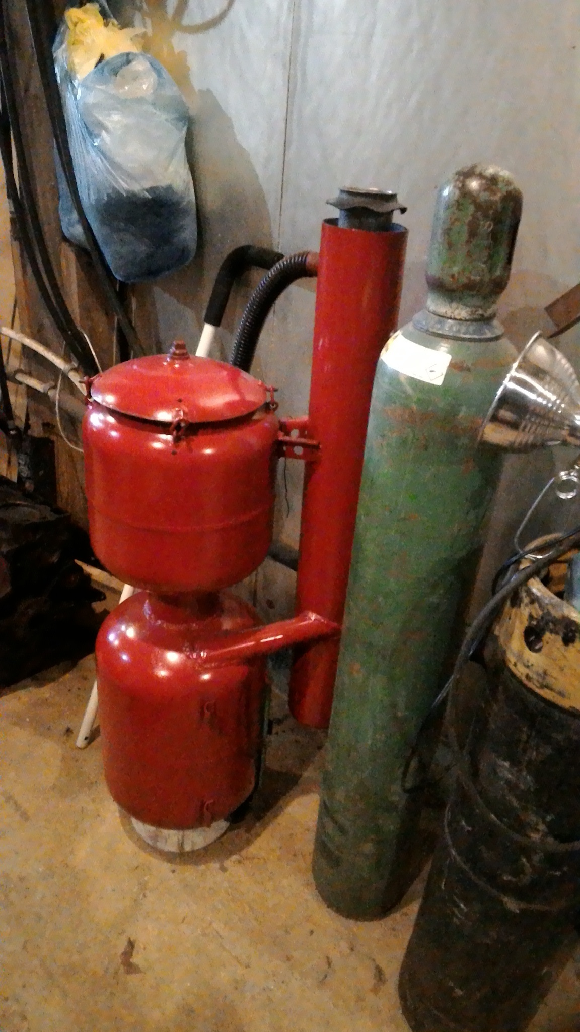
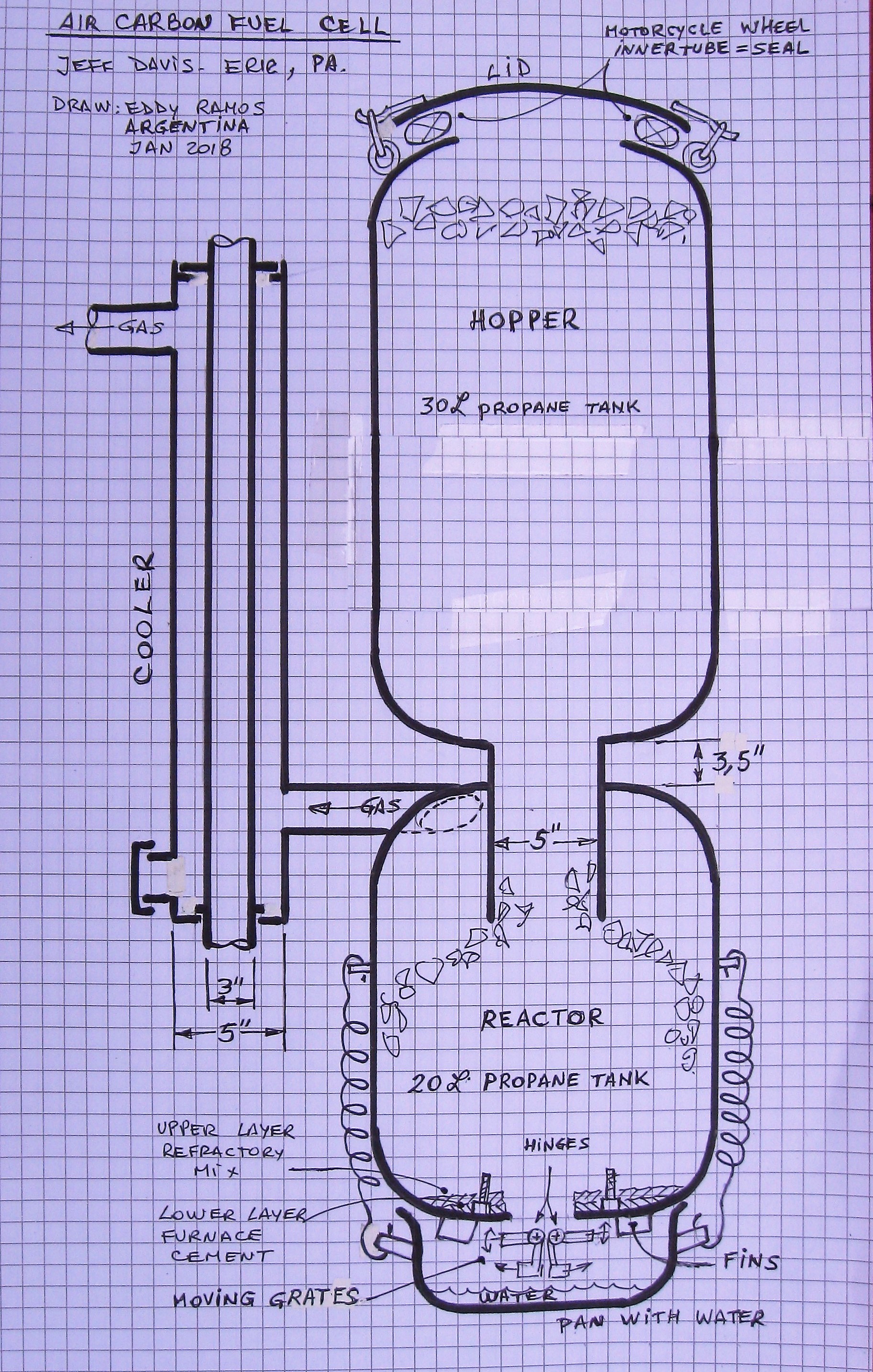
Since the gas is removed as fast as possible without traveling through the charcoal fuel supply a gas cooler is used. It is a pipe inside of a pipe with tangent inlet and outlet on the outside pipe.
Hmm, I forgot to take a photo of the complete cooler. I’ll do that later.
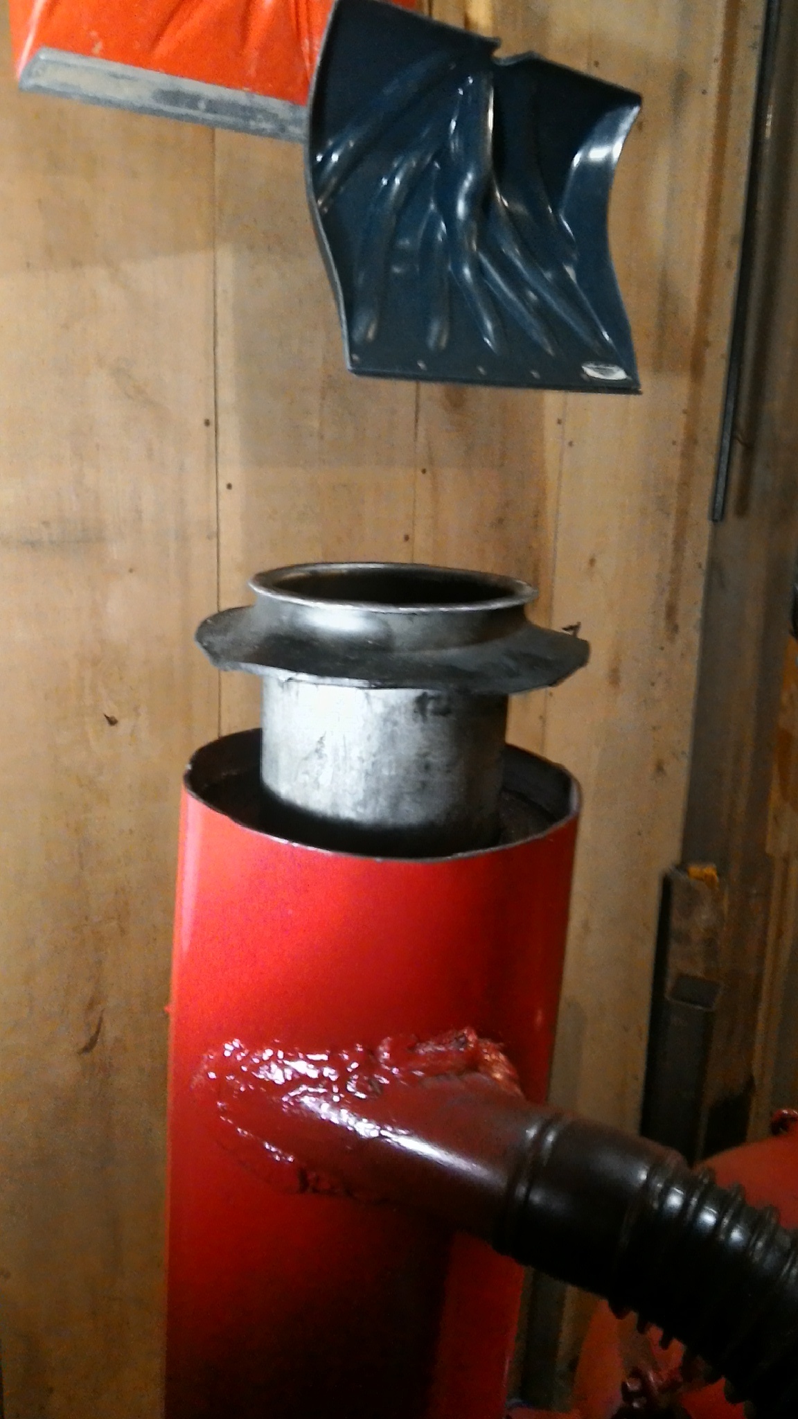
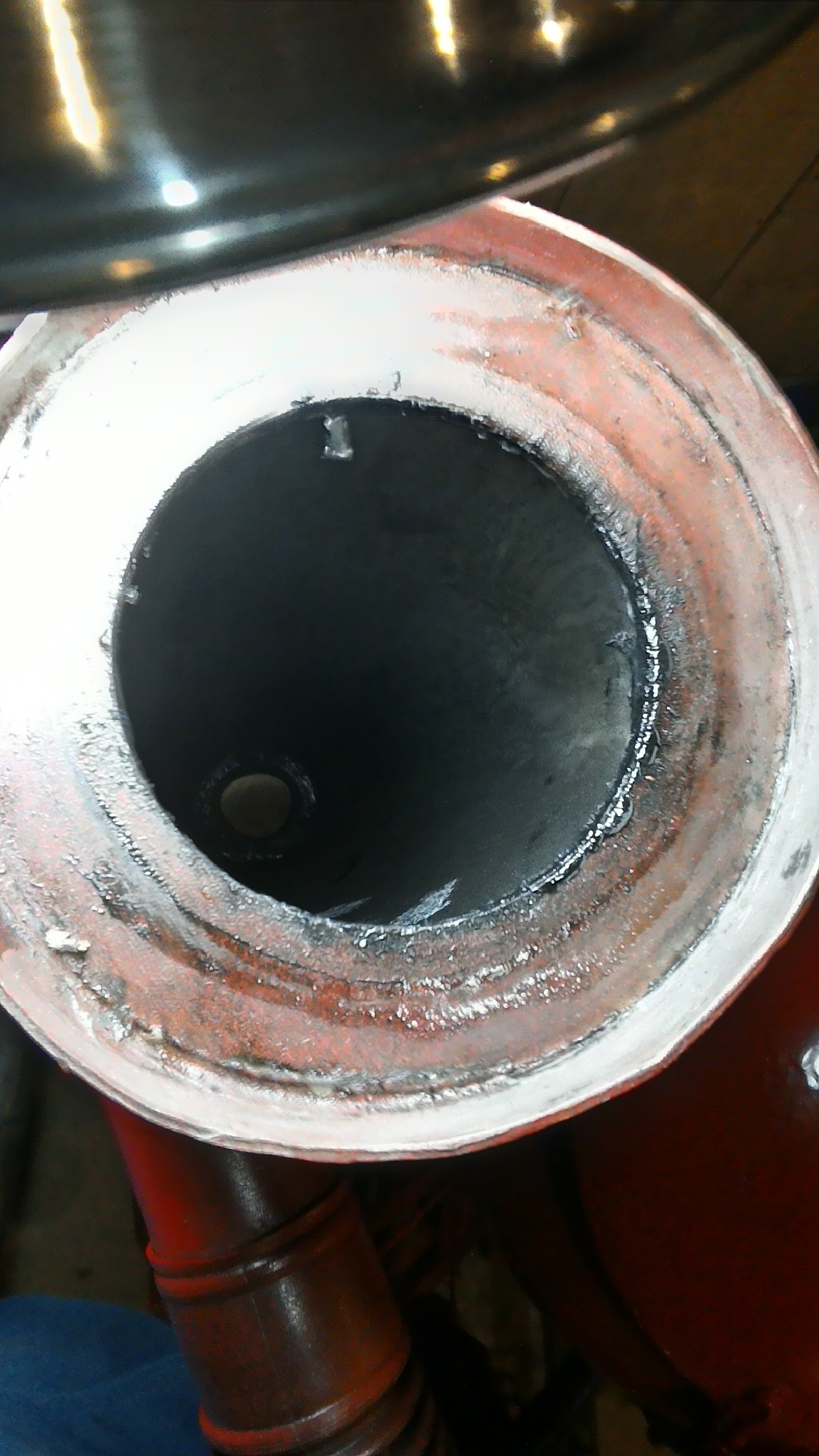
This is the inside pipe. I like to oil it with canola oil at least at the bottom so that it slips into the seal made from tractor inter tube.
Hi Bob, Water will collect on the bottom, sometimes, Dust and condensed water collects on the walls but not as much as one would think. Well, one time when I over sucked with the starter fan I found an amount on the bottom with water.
It is different than I thought. I see that it is more of a cooler than a cyclone. I didn’t realize that the center tube was a passage for cooling air. I thought you had a cyclone with a sock filter chamber attached to the cyclone outlet pipe.
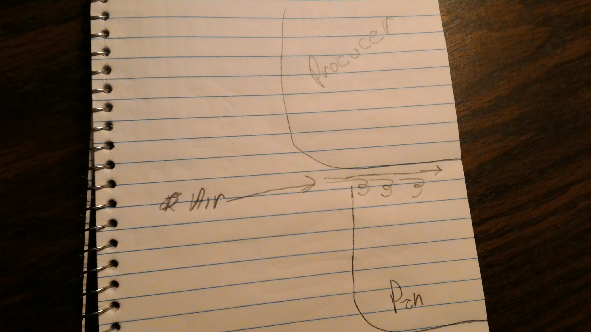
I was just having fun with words, it is just another gas producer.
Efficiency, now there is a can of worms! For this old boy, efficiency is really the state of being practical. How easy is it to use, how repeatably is it and how much maintenance is required. Anybody can cook the books to come up with a percent of efficiency but it is not easy to fudge those three things above.
Oh, you meant the cooler. I forgot to mention that I coat the inside with used engine sump Canola oil to stop rusting. That is why some of the dust sticks to the walls and doesn’t fall down, Next time a stainless inside tube would be my choice. I’m thinking; if the inside tube rusts, it might wear the rubber seal when installing or removing. But I bet it would be microscopic, in other words not a real problem.
Hi Jeff.
You asked me to make you a clean sketch of your producer so I have studying this topic from the begining, and follow the different modification that has suffered your desing…when finally in post # 85 I saw your skecth.
Please I will need some basic info:
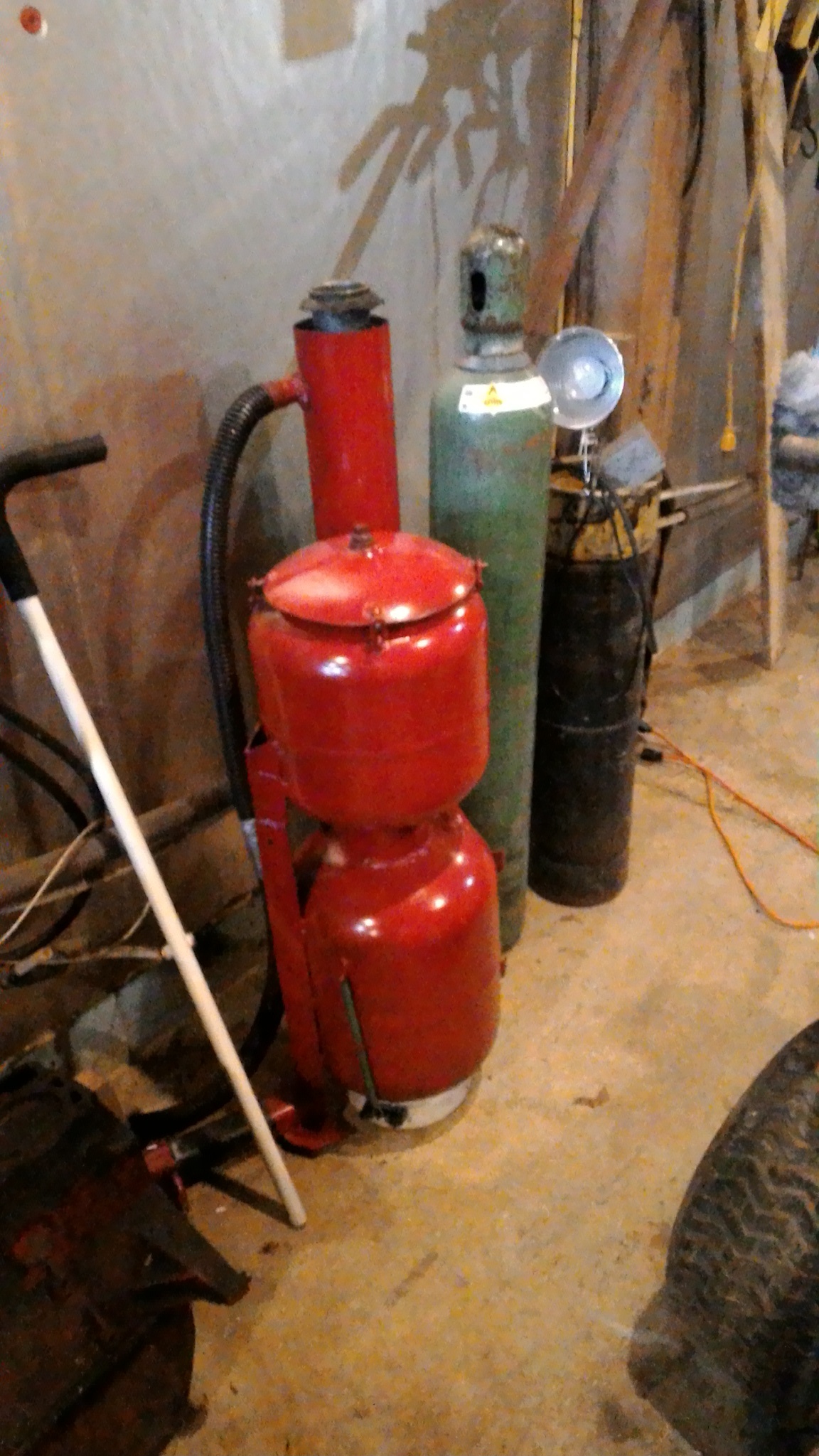
The type and size of the engine that this producer feeds, and what kind of vessels are you using for the top hopper and for the reactor, Some sizes??
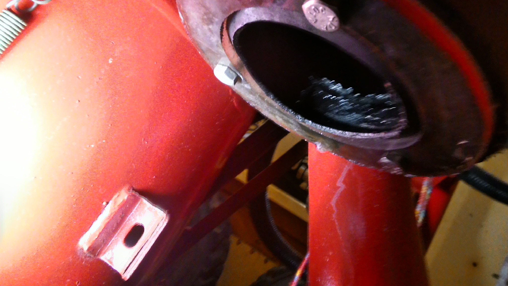
BTW: I think that the reason why the reactor work better without the spacing wires is because the inlet air has to squeeze between the pan lip and the bottom of the reactor this way he air is being better preheat (hotter) because 100% of the air is “licking” the bottom of the reactor that is hot.
Yep.Yep. Well, well said.
Efficiency mania of each separate step DOES not lead to “better” usable results.
Just spends a lot of non-replaceable time and money’s.
Every single failed 1990’s idealized “better” bio-mass systems failures can be traced back to sinking from obstinately insisting on single failure point better-efficiency blockages. Gas turbines & Stirling cycles engines versus proven IC piston engines. All-biomass systems capability hinted at by slit-hearths with formed “fuel-cubes” and/or plasma & fludized bed systems with ground particlized fuels versus just chunked woods and made and sized wood-charcoals.
Read these Idealization efficiency chasing’s and weep.
A couple comments:
The bolts, that help grip the refractory, are covered with the refractory. The bolts are not exposed to the charcoal or glowing charcoal.
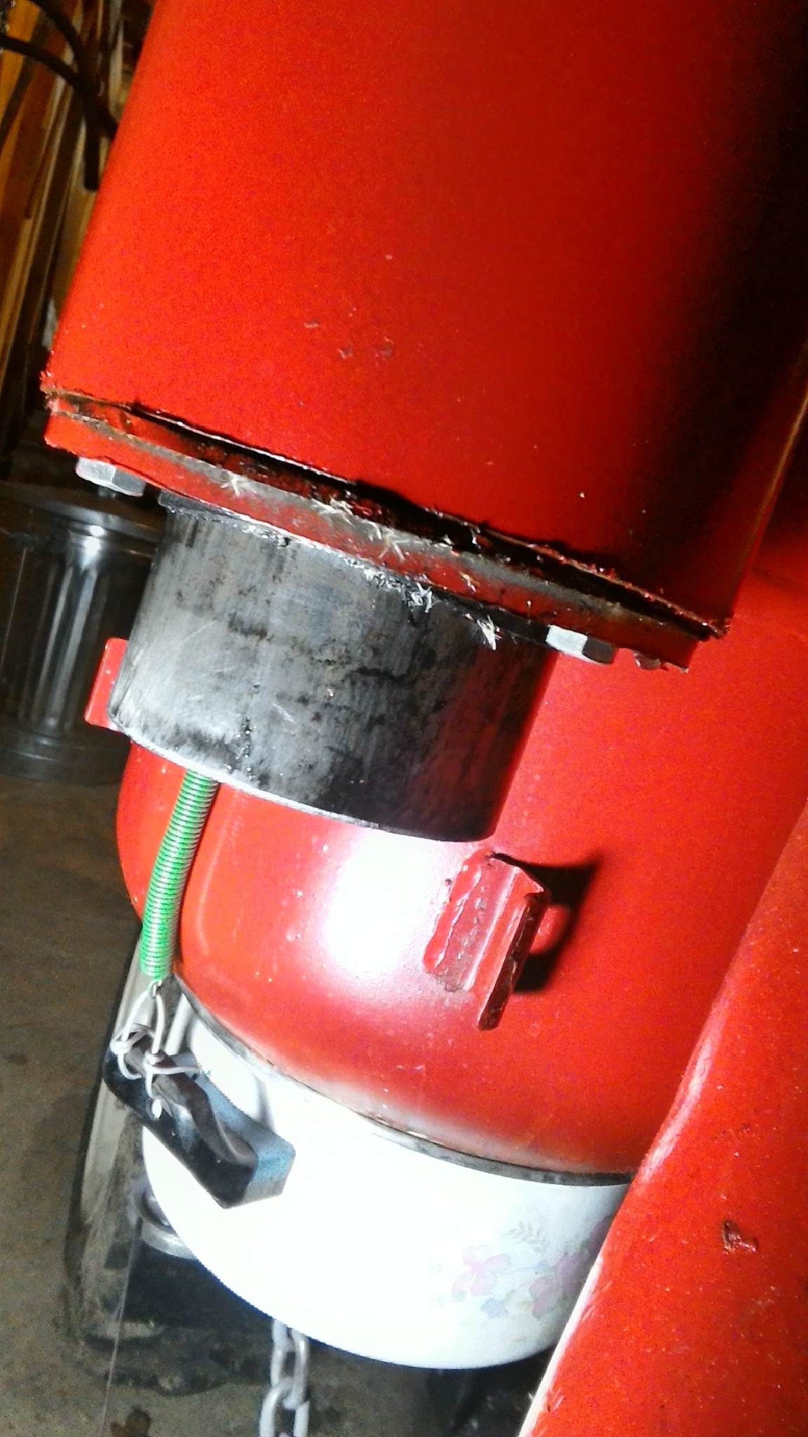
No bottom/side clean out on the cooler. The inside tube is easy to remove, serves two purposes and no tools needed to remove.
Al
When i first saw this at Argos I had a difficult time understanding what was going on. Jeff kept telling me and I still didn’t get it. This is what I left with and jeff can correct me (again) if I misunderstood.
When running the pan underneath is held off the bottom of the producer a little ways allowing the air in at the bottom. Shut down the pan is sucked up to the bottom of the producer shutting off the air flow.(springs) It is so simple that this mind couldn’t see the forest for the trees. My mind was struck in downdraft mode that I couldn’t recognise updraft mode let alone only halfway up updraft. More hopper on top.
Ok Jeff you can now chastise me.