I took the gasifier apart so you guys could have a look. All of the leakage on the outside of the tank is from the top cover. Pulled the reduction bell & screen down, dumping everything to the bottom. I really do not know what I am looking for. From tip of nozzle to nozzle is 10.00. Fire tube diameter @ nozzle ht. is 13.50. At the first step out over the nozzles, the fire tube is 15.00. The rest of the tube is 20.00. Top of bell is 2.50. The bottom is 9.00. The screen is 11.00 dia. Nozzle ht.is 2.00 from top of bell — 4.00 to floor. The screen hangs 1.250 below the bell ( sides of screen .250 over bell.) 10 nozzles with .290 openings. The hearth is made out of a 16in. budd wheel, jacketed for the nozzle air & fed by a 1.500 tube, not preheated. Does this design have any inherent flaws? After looking at Wayne’s units, the reduction bell system that I chose to build may be a problem. This is easily changed as it bolts in on an 8 on 8.00 pattern. The outer tank is 23.50. Well, I guess I just need to know if this unit is worth continuing on.
Peter, The protruding nozzles look like they may allow for some bypassing (easily fixed with a drop in collar) but the restriction is small enough so everything will get toasted somewhere. Bottom line is how does it work ?? Am I Iooking at a 2" outlet ?? Better be thinking 3" for anything going down the highway or a pair of 2 inch in parallel. What is the restriction diameter ?? Mike L
If I understand correctly you have 2" from nozzle to bell opening. Increse this distance. It will give you more char. Sounds like mabe your getting oxygen past your char area putting it into heater mode. Anything MikeR says will be great advice. Defanetly a good start don’t trash it there is potential.
Along with what Jim has said I think we need to increase the reduction from 2.5 to 3.5"-4.5". If you just cut the top of the bell down, this will also increase the nozzle height.
Also 1.5" air intake is a little small, but can work.
Most of it looks sized pretty good.
Terry
Terry & Peter, On my 66 chevy I had a single 1-1/4" ID inlet and I thought it was cheating things so on Father’s Day several years ago I cut another hole and welded in a second 1-1/4" nipple and ball valve. It made no difference and mind you I was running a 4000 or so pound car with a 283 V8 at 55 to 60 mph down the highway with it. I did add a series of extra nozzles to eventually boost the power up. I believe it has a 5 inch restriction but it also has a long 6" reduction tube … Before I added the extra nozzle holes it would run so cool the reduction tube would plug up with ash mud … Ignition sequence starts in a half hour for a local parade (Art in Motion in Mineral Point) … I hope some one takes a few pictures … Sue will be playing accordion in the passenger seat … Parades are tough to do on wood … Mike L
Peter,
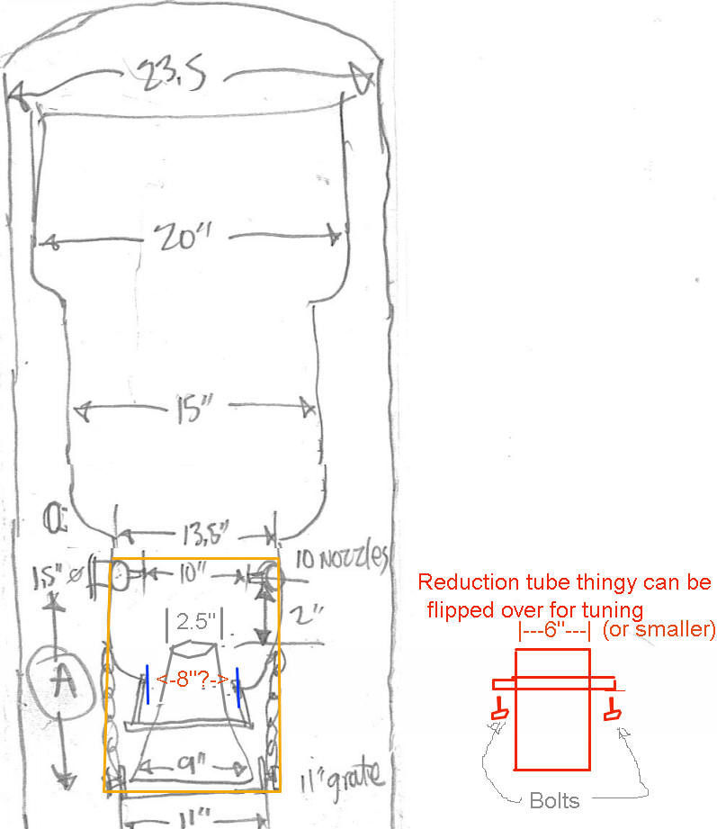
I think it will run an engine with some tweaks…I could not resist making a drawing. Please correct me if I have mis-understood the measurements or names of the innerds. Assuming all dimensions are in inches… I am just guessing on the vertical scale of this, but the area of the gasifier identified as “A” as the kinda red box is where most of the real action happens. 2" is too tiny for sure at the top of the bell, If the bell can be taken out, bolt in a reduction tube welded to a collar in the area noted with the blue bars (8" opening?) with the size recommended by the real engine running experts…
Consider a piece of 6" diameter (or smaller) tube to replace the reduction bell, to make sure all the hot char gets in it, and all the gasses simmer inside on the way through the grate. Make a “donut” flange and weld it somewhere near the middle This 6" reduction tube thingy would act like a restriction bell but be easier to make and provide less restriction and give some tuning capability for distance from nozzles and grate.
Please note I have no experience running an engine yet… but I CAN draw pictures for what it’s worth : )
Hi Mike, The outlet, or as i called it the top of the bell is 2.50in. Is this bell set up necessary? I do not really understand the drop in collar. I have not
seen how everyone is setting up their adjustable restriction plates.
Hi Gary, Your drawing is pretty close. The 15.00 in. marked A is actually the diameter of the fire tube approximately 1.00 in above the nozzles. I do not know if this system is correct or not. I am going to wait until someone tells me yes or no before i modify it.
Hi Jim, Yes the distance from the nozzle to the bell is 2.00in. The opening at the top of the bell is 2.50in. How much would you suggest cutting off the bell? Should I install shorter, heavier nozzles?
Hi peter, As TerryG has suggested go 3.5" to 4.5". This will give you enough gas to run more than a mower. Then measure distance from nozzle to opening. Give your self 5 or 6". You need a good char bed so the oxygen is all used up befor it reaches the grate. Your nozzles should be ok. Sorry for the typo MikeL.
HI Peter,
I do not know of the intricacies of the reduction bell, but in my simplified understanding what that part of a gasifier does, it is a conduit or doorway to make sure that every bit of gas that passes through it is given the chance to react fully with hot charcoal after all the oxygen has been consumed by the burning (pyrolysis) zone above. A bell shape that is narrow at the top will clog (if it is too narrow), and with it wider at the bottom, the char would drop right to the grate and be loosely scattered, possibly burning on down to fall through the grate rather than piling up nicely (like in a pipe) for maximum reduction and a better chance of “cracking” the tar compounds. Just my opinion, but you have to think of ways to get the hot coals in the right place to do their job.
I suggested a pipe with a collar offset from the center so you could try it one way, and see how well it works, then unbolt it and flip it the other way and see if it works better. This is assuming you can unbolt the reduction bell from the 8" flange and bolt this reduction tube thingy in place of the bell.
I updated the diagram above with the 2.5" bell opening and more details on the proposed reduction tube thingy.
Hi Gary, I think fabricating an experimental reduction tube is what i need to try next. If the new tube is flush with the bottom of the hearth, it will give me
4.00in. of char to the center of the nozzles. How long should the tube be before the grate?
Hi Peter,
I’m not sure what you were using for suction and whether ya know how much vacuum you were pulling?
This wood be useful to know.
I have had a gasser that works very well to run an engine… Make nothing but tar and pathetic flare while being under pulled by a fan not suited to the task.
Looking at it briefly your gasser seems to be in the ballpark, Depending on what you were planning to run with it.
You need a significant source of vacuum to get that puppy out of the tar zone.
And a specific target size. Can’t make any real progress in tweeking till ya know where you are going with it. Engine size and what RPM it needs to run at. It’s an Imbert, gotta play by Imbert rules. With Waynes it’s a different ball game.
I like what I see, definitely got some potential.
Hi Terry The fan i built is a 3450rpm burner motor with a 4.50in. dia.squirrel cage. I never took a vacuum reading on it. There is a picture of it running.
I really don’t know if it is adequate or not. I agree, this also could be a problem. The real problem is that i have never seen a gasser. I built this unit
completely in the dark & i am just trying to learn the hard way.
Peter
I’ll tell ya, What ya got there beats my first attempt by a mile
At first I used draft induction fan from water heater. (made awesome tar)
Eventually what I did was… Estimate the the nozzle area, then I left an opening that size, plus the diameter of the probe for the manometer.
Inserted the probe and monkeyed with til I had ten inches of water.
Ten wasn’t enough to fully simulate an engine pulling hard. But in that gasser it was adequate to make viable gas. It will vary from considerably between different gassers and conditions.
Is the fan centrifugal, squirrel cage? Do you have pics of the innards?
You can also use an Ejector to get suction.
TerryL
Bummer,
Very useful tool it is.
Well, if ya have high speed consider installing it.
There is always the Telephone as well.
If not, You can go to DJ’s site http://woodgas.nl/GB/diy.html and do the math for you’re restriction and nozzles
The Stephen Abbadess has posted some very good info on how to make an Ejector using a Compressor or a Central Vacuum Fan.
I can look it up if you haven’t seen it
TerryL