Thanks pepe… Much appreciated.
Hi Pepe
Nice short video. Easy download. YouTube will no longer allow me to comment there without a change to real name. Good. What I wanted all along anyhow. That Google environment there does not want to play nice with my Yahoo email address to complete the change now. So there you are.
I did not think your blower was all that noisy. It will quiet down some once air loaded down. Was picking up a harmonic though. If you ever wondered why belt driven factory engine fans have the unvenly spaced brade arragingment it is to disturb harmonics reinforcements. You see the same thing on quality tire tread block spacing for the same reasons. Get rid of the annoying, “wah, wah, wah’s”.
Hint: if this is irritating just try re-space two opposing fanblades out of perfect aligment.
Regards
Steve Unruh
Hi Steve,
Thanks for the comments, they’re always a learning experience. I picked up on the harmonic, too, and said, “what now”? Glad to hear it’s not something out of alignment. Guess I’ll hold onto your hint until my next fan, lol. I can’t believe how much time I’ve spent on this fan already. Fun, though and now I’ll do some temp, pressure testing, more fun.
Take care, Pepe
Hey All,
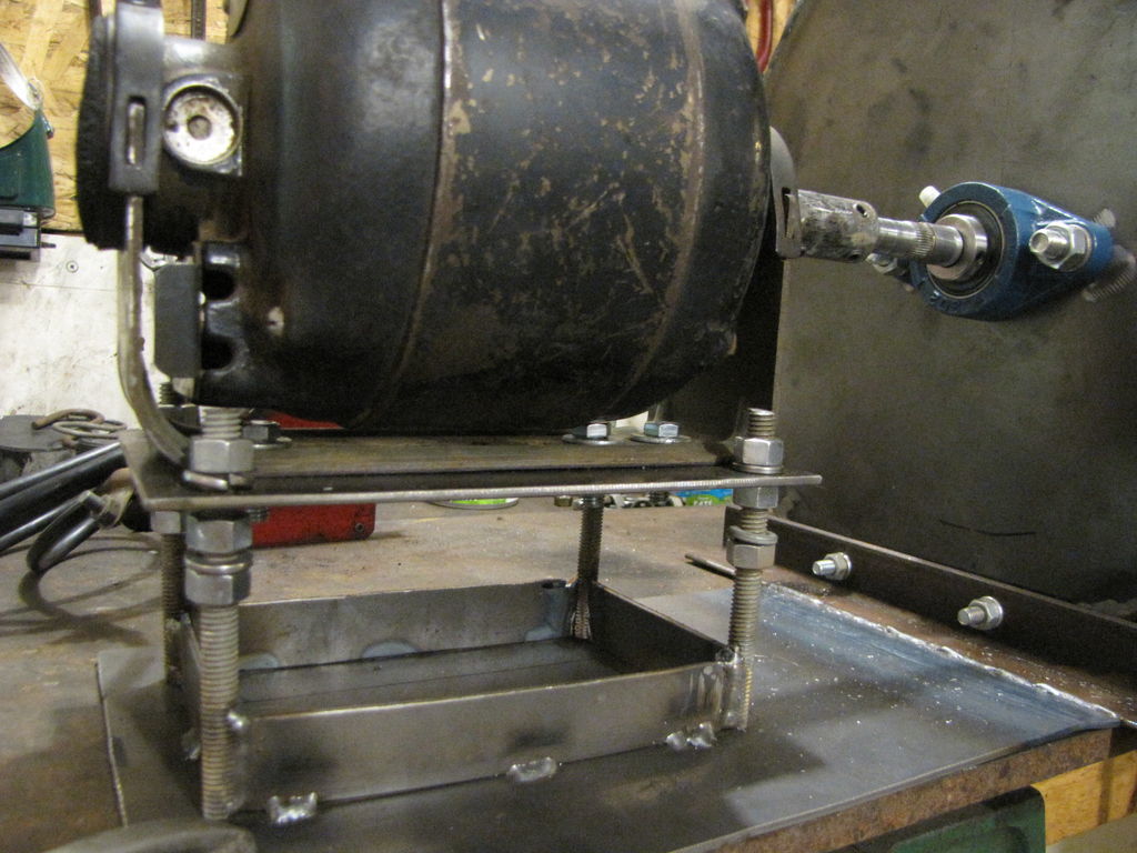
I spent some tinker time today and set up for a water column test of my fan. I posted a short vid here
http://youtu.be/FAZLB7ErgRs.
I’m going to try a bigger inlet (s) also when I get some time.This inlet was supposed to be 3.5" but it’s only 3".
Pepe
Update: See second pic. I forgot to tighten one of the adjusting nuts so that’s the rash sound you hear on start up. It’s quieter now.

Hi Pepe; Only 3" of w/c ? I guess thats why you want to try a larger opening? Just a guess on my part, but I think you need to add some back pressure to read a higher volume. You know, maybe 3" hose hooked to a drum with the equivelent # of holes/nozzles and diameter of of holes in a gasser. Bet your w/c would jump up. Right now it would be like me trying to measure w/c with my hopper door open.Listen to me, I build one unit and think I know it all! L.O.L. Dan
Hi Dan, Thanks for your comment, Yeah, that’s what I said, only 3". hmmm. I variably restricted the inlet with a flat plate to simulate a load and the pressure dropped. That’s why I thought a bigger inlet was needed. I know when I ran it with the side cover off the output could knock you over, so to speak.
Gingery points this out on p22 with comments about 2 ratios, the width to diam and the inlet to diam. The diameter is the diameter of the rotor and the width is actually how thick the rotor with vanes is. Mine is about 3 1/2" thick and a 10" rotor. The formulas don’t take these into account so he goes on to explain how each ratio affects performance and leaves the proof up to the student as an exercise. Now, where have I heard that before, lol!
So my easy out is to mess with the inlet shape and size. By shape I mean shape of the inlet. Most commercial units I’ve seen have a shallow cone with the large end toward the rotor. I may try that if I decide I need more torture, lol! Pepe
By the way, Dan, what are the dimensions of your fan, rotor, etc. Thanks
Today I received a blower from Surplus center. It makes 1.2"wc no matter what you do to “block off” the input. I wonder why that is.
Now, I will go back “to the books” (the Gingery pdf I got from you) to see what I can do to make a better wheel for it. I have not tried this business of blocking off the output to see what changes.
What did you use to make that nice blue color in your manometer? Is the fluid still mostly water?
Pete Stanaitis
Hi Pete,
I don’t know the answer to your first question, but my fan makes 1.9" wc when I block off the inlet. I blocked off the outlet just out of curiosity and it made 0" wc. I’m going to try bigger inlets.
That great blue is Durkee’s food coloring, it almost glows. Mix it as blue as you want using all water.
Do you have av picture of the wheel and housing you can post? Thanks.
Pepe
Hi Pepe; The first time I saw the size of my impeller I about fell over. My fan is the motor and impeller from a shop vac. I made a new housing out of 1/4" steel plate(I build to last) maybe 5-6" in diameter and appx. 2" thick. Now here comes the surprise, the impeller from. the shop vac is about 4-5" in diameter but only 1/4’- 5/16" thick(who would have thunk). I read somewhere that the skinny impeller will move less air but more velocity and the fatter impeller will move more volume at less velocity(at least that’s the way I think I read it, can’t remember where). As far as the water colume goes, if I have a full hopper it draws higher and if I have my lid open on my hopper it draws way less.At this point, I don’t know what to tell you. I know you will get it. Dan
What you’re measuring is correct - close off the inlet and measure the vacuum generated. SImilar test is to close off the outlet and measure the pressure generated - should be similar. This is your static pressure.(try holding your hand over a vacuum cleaner hose - no airflow, lots of pressure).
From what I’ve read, static pressure is increased in only two ways, related: rotor diameter and rotor speed. You could say then it’s effectively the “tip speed” of the blades that causes actual air pressure - you’re flinging air really hard against the wall.
The way shopvacs do it is with speed. That turbine whine comes from around 30,000 RPMs, though the rotor is fairly small at 5". The reason it’s so skinny is to reduce the air moved per revolution - less load means the rotor RPMs can increase (and the pressure). Vacuum cleaners don’t move tons of air, but they do make lots of pressure. Something to keep in mind for woodgas (no need to move volume, mostly pressure)
Pepe, if you try a 3400 RPM motor I think you’ll see a huge boost in WC. In fact if what I’m reading is right it will increase by the square of the RPM change. (double speed = 4x pressure). So you’ll have the 12" WC you wanted.
Link: http://www.na-stordy.com/seminarCD/ppts-converted/blowers.pdf
Hi Dan, Thanks for responding. I’ve been thinking I about the the vacuum cleaner configuration as Gingery explains how it develops pressure, even feeding outlet of one fan into inlet of a second fan. Chris suggested using a faster motor, which I have, just a pain fitting it to my setup, need a new mount. But I think it will work. I’ll post results. I guess size isn’t everything. Pepe
PS I’ll be taking the motor and fan out of an old shop vac also and seeing what I can do there. Pretty interesting stuff, but it’s chewing into my seed flat planting time, lol.
Hi Chris, Thanks for the pdf file, it’s VERY informative. I wish I’d had it before I started to build “Goliath” lol. Gingery did touch on this but I told myself it was too much. Looks like I’ll try my grinder motor again as it’s the only 3400 rpm motor I have. I’ll see what happens. I may also build another fan with narrower rotor since as you point out I want pressure more than volume.
Pepe
Hi, Richard.
Thanks for the input on the blue coloring.
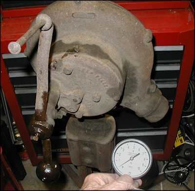
I think I am attaching a picture of the McMillan blower that I was talking about. Mistake!!! I meant that the pressure at the output didn’t change when I blocked off the OUTPUT!
After rereading the Gingery pdf again, I can see many reasons why my blower doesn’t do any better than it does. The shroud is 2: thick but the fan blade is only 1" thick. Note that the blades are very short, too.
The wheel is 6" across. One of the reasons I chose to try this blower is that the motor is 120vac, but it draws 1.38 amps, quite a bit more than many other “corn stove” and similar blowers do.
Pete Stanaitis

Hey PeteS.
Before you give up on this look at the turbine blower pictures at the end of the pdf that ChrisKY put up.
IF on your current blower you were to make a solid backing plate out of thin aluminum and attach on the backside this will enclose those now pressure bleed off slots . . . .
THEN do the same on the front/top inlet side of this “fan” . . . . keep your center hole say 3 inches to begin with . . .
You could slim thru nut and bolt these on sandwiched through the existing fan legs . . .
This will then low turbulance channel deliver the flung out condensed air to the outer fan/terbine edges and stop the over the now open blade edge turbulence spilling/churning going on.
Bet you then see a 2X in performance for pressure capability.
Done this way, as they are doing it, the fan/turbine to side case clearance become non-critical.
What IS critical is to let the flow OUT to prevent central internal case pressurizing and then turbulences.
You can then play with center inlet hole increasing until the performance fall off. Then back up in hole size down. Once there, another level of performance can be gotten with an short inlet side housing flow in tube down into the fan blade to guide the air in and prevent internal housing re-flowing.
Good article ChrisKY for primary factors. Math challenged like me then just hippy, skippy once past the beginning pictures and good words to the last third of the article to the great pictures, charts and graphs.
The devil in details of secondary factors for blower designs for our purposes of high pressure relatively low volumn are all there if you really look and see.
This is for gasifier normal operation BYPASS blowing or sucking fans.
DYI inline primary air always flow-through gasifer pressurizing types are whole differnet animal covered in Vesa Mikkonen’s book.
Regards
Steve Unruh
Hi Pete,
Thanks for posting the pic. On my fan there is a 3/8" space on either side of the rotor, Gingery says this isn’t excessive. I would stay with a 1/4" if I was building another one. The thing that struck me was the scroll. In particular where the air dumps into the outlet. The bottom of my outlet is even with the top of the fan blades not well below it as this fan is. Draw a line at the top of the blades parallel to the top of the fan. Now make a wooden plug the shape of the section below the line. Try clamping it in the outlet and see what happens to the wc. This will decrease the size of the outlet. This is one of the 2 ratios Gingery talks about on p22, I think. It’s also where I’m at now with my fan. Dibble with this, dabble with that, educated guess wise anyway. I’ve attached a pic for design comparison. Notice how far up the scroll goes towards the outlet.
Link to my faster fan motor wc test

Pepe

Good catch, Steve, I’d better put my readers back on. Pressure bleeders they are.
Zero Volts Blower Makes 4+"wc!!!
I am attaching 2 pix of an old forge blower that I dug out today. I oiled it up and cranked moderately hard, but It makes over 4 inches wc. I am sure that I have seen pix of WWII vehicles with such a starting blower.
Steve: The fins on that McMillan blower are even worse than they look in the picture. If I have the ambition, one of these days I may make a new wheel and try a couple of other suggested changes.
Pete Stanaitis

Hi there,
in todays hangout, I showed my “new” blower off. It is an “Electro Star” 12 Volt fan that was originally mounted in an Imbert gasifier setup (kinda OEM, I guess…). Found it on Ebay for 50 bucks and couldn’t resist. Its wheel or impeller is actually made of stainless steel. I was told it should still be running, but haven’t hooked it up, yet.
If so, that’s not bad after 70± years. The only problem is, the inlet and outlet are 50mm diameter (2"), which seems a little narrow for nowadays engines…
Cheers,
Sam
PS: Please excuse these bad quality pictures. It was already dark outside and there are only neon lamps in my office…

Hey Sam; Those are very cool! I thing I would have purchased them just for the history alone. Dan
Are you sure that is 12 volt not 6 volt. I didn’t think things went to 12V until about '56. Don’t melt it down the first time you run it.