Hi Pete and Sam,
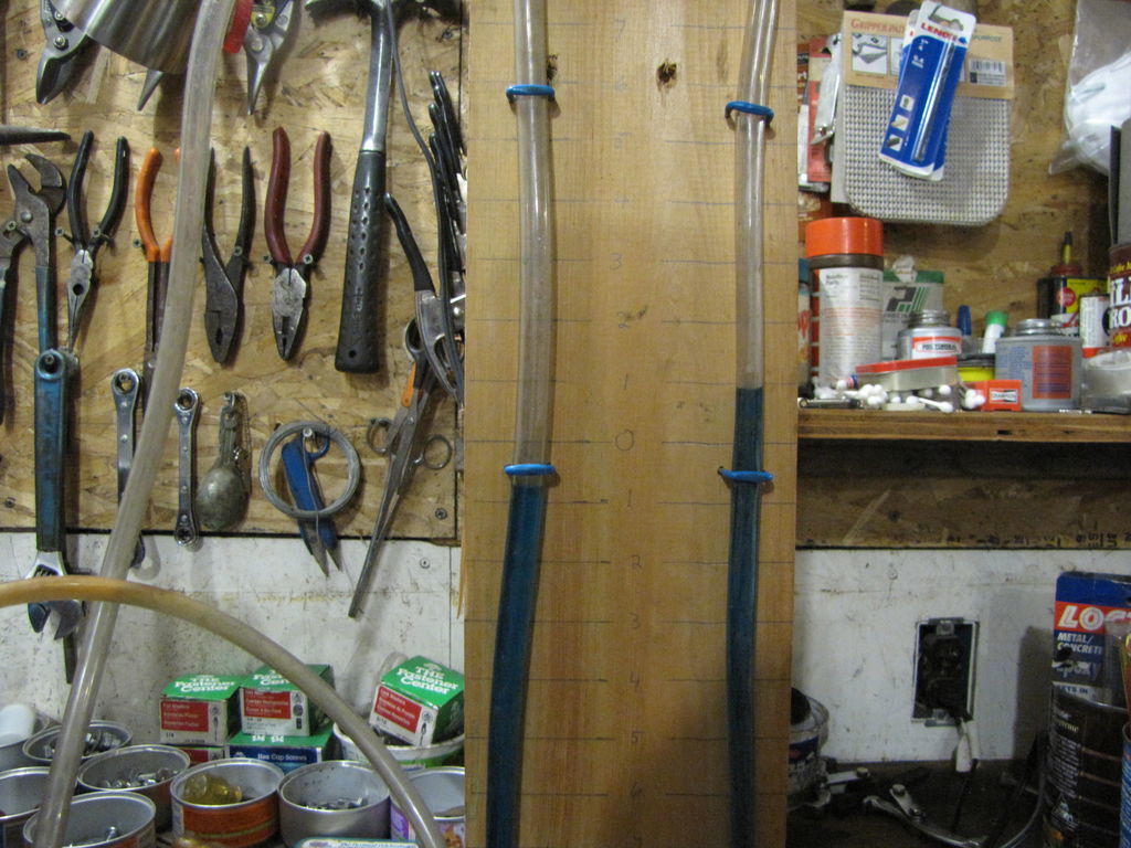
Thanks for the photos. My 5" outlet trial (first 2 pics) made a paltry 1 1/2" wc, but still puts out a big volume of air, Pete, you have to love that cast body and bolted assembly, darn, no welding. Interesting outlet location, if you ever take it apart I’d love to see the inside. Sam, it looks like your rotor is right on the motor. Same request for a look see inside.
Both units have that narrow (thin) rotor and as I look back a lot of units share this trait. I’ve decided to cut my housing down to accommodate a 2" rotor. Housing cut was a pita, cutting an inch off the top of the vanes and re-cutting the inlet angle on them is all I have to do to make the rotor.2" wide ( thick, I say). In the last pic I will cut the excess flush with the cover plate.and weld it back together. Give it a try and report. All cutting was done by file, small hacksaw, Delta jig saw and sawzall and took 45 mins.
Pepe

Hey All,
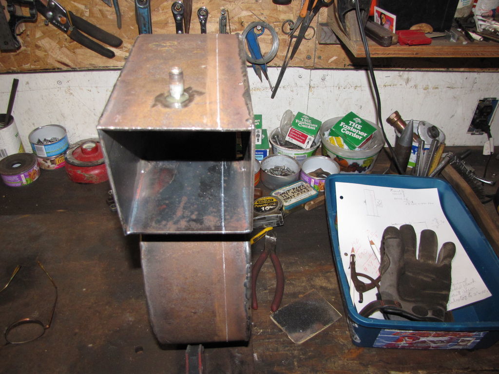
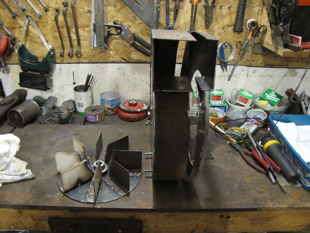
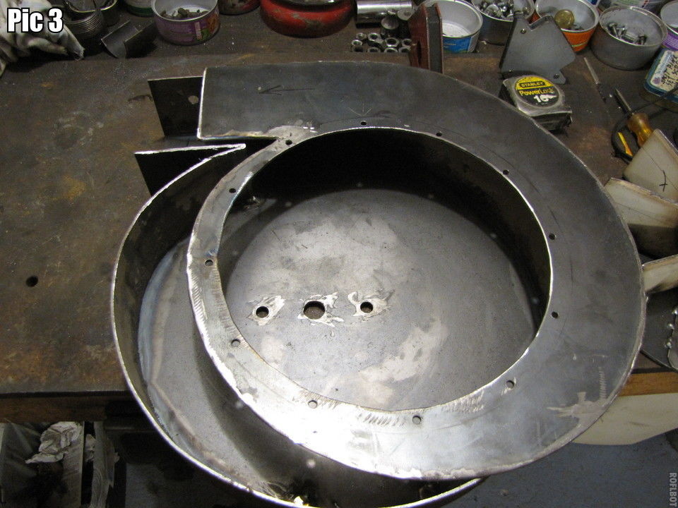
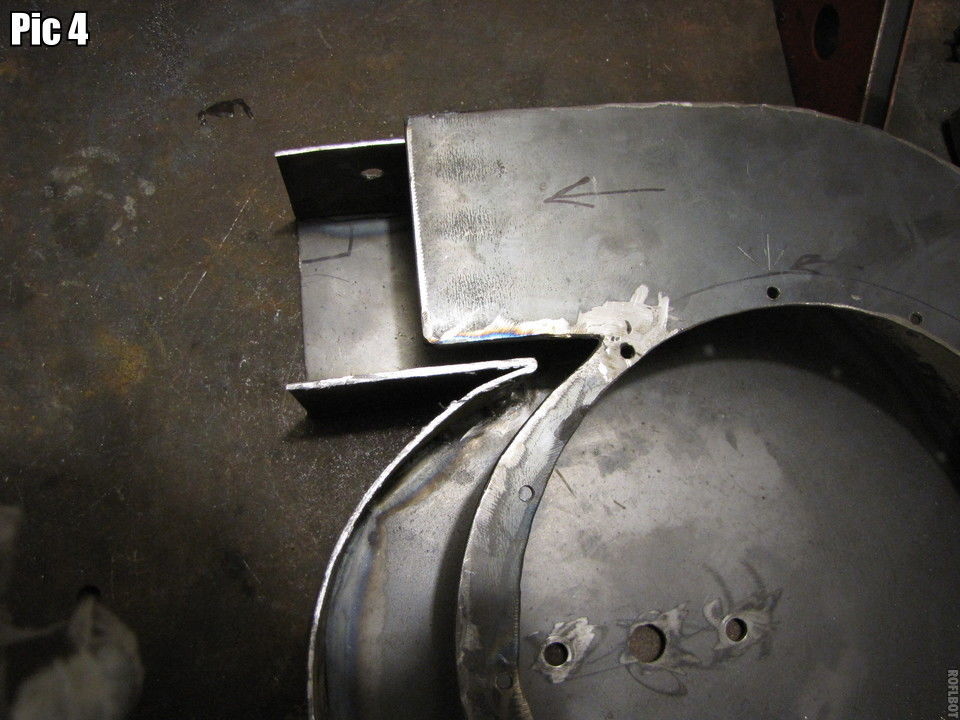
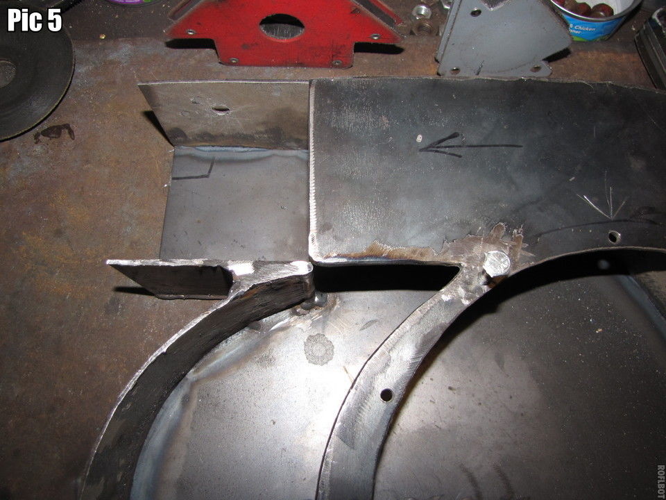
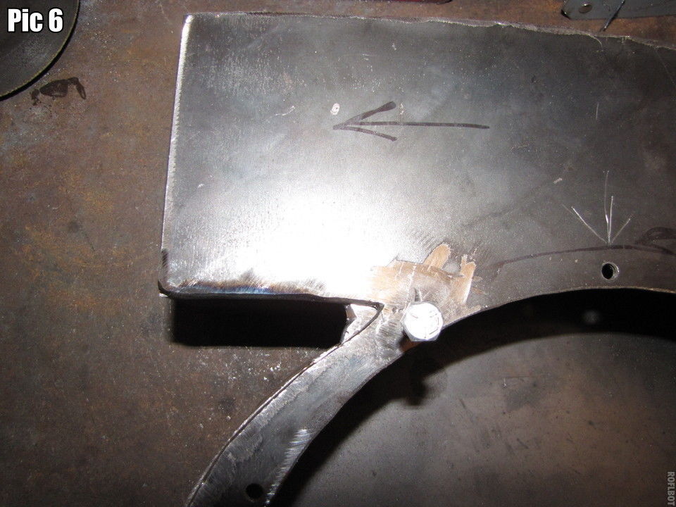
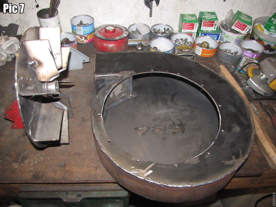
What a nice early spring day I had to work outside on my fan mod. I don’t recommend removing any guards from tools! PIC 1 rescuing the inlet side cover. PIC 2 Twenty or so mins. to slice it off. PIC 3 Oh, great another tight corner to weld up. PIC 4 Avoid my mistake of locating a hole near this tight corner. Shift the axes so there is a space there, not a hole. The bolt just misses the inside wall by a 1/16". PIC 5 Weld up and grind a land to weld the cover to easier and assured air tightness. You could also use the ends from the original cutout to weld in for this land. PIC 6 Don’t land a bolt here, lol. PIC 7 Inlet cover plate welded on and vanes cut down to make a 2" wide rotor. Vane angle cut to match 3 1/2" inlet diam. PIC 8 Another view of the vane angle.
I’m hoping to be able to get it together for a trial run tomorrow.
Pepe

Hey Everyone,
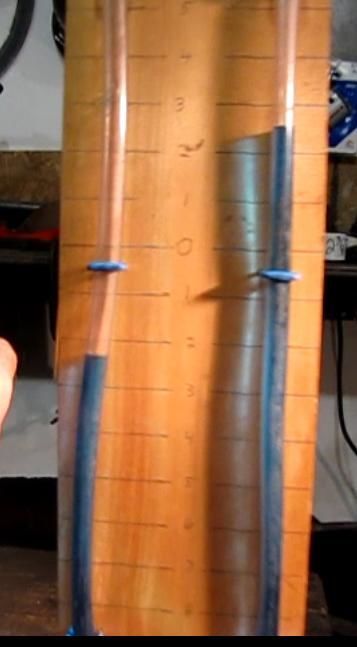
I ran my thinner version and talk about, “much ado about nothing”. I’m now making only 2" wc so I thought I’d try double siding the rotor. Still much ado about nothing, the wc remained unchanged at 2". That’s all she wrote for this boy. I’m going to try it as is and see how it works. It still puts out one heck of a volume of air at a quite forceful stream, so I’m a little baffled at this point. Looking to pull apart a retired shop vac just for something to do in between my " much ado’s" lol. My best wc was the original “goliath” at 3".
Pepe

Pepe, did you ever try speeding up the rotor?
Hi Chris, Yes I borrowed and jury rigged my grinder motor (3450 rpm’s) and made 5" wc, 2" up from 3". I haven’t tried that with the thinner unit yet, but I probably will tomorrow, It’s a real pita , have a real tight fit on motor coupling so I have to remove rotor, motor and flange bearing to uncouple the driven shaft in order to install the grinder motor. Sigh, I’ll try it again and report. lol.
Pepe

Hey Pepe
Ok you done with the maths and formulas for a bit, eh?
Wanna try my method and “feel” the problem?
Take your shop-vac and if it is decent it 'aught to be able to pull a 10" WC. Now on the blowing side of it hand feel the pressure generated.
On a car with the window down airplane wing play around with one hand stuck out. I find it takes about 60 miles per hour speed to duplicate this air push. You the light plane guy. Is the air really pushing? Or, is your hand being pulled by the lower pressure bubble you are creating on the back side of your hand? See? That shop-vac IS actually doing that too on the suction side to the blowing side. THIS IS what we are after.
So I have found I need to spin/fling the air to at least 60 miles and hour first and foremost period. THEN secondary with enough volume flow to really suck a gasifier maintaining this pressure difference.
A shop-vac does this with a little, iddy-bitty 4-5 inch EXpeller fan then needing at least 5000-7000 RPM. Open bladed Toro/leaf-blower 4-4 1/2 inch turbine EXpeller’s also need these same mondo speeds. Open blades on these are needed to be able to chew eat up sucked up, flow through debris. True dedicated vacumn makers always use enclosed bladed fans to be able to create an expelled pressure difference with the least internal turbulances and therefore wattages needed to drive.
The effective centriugal assemblies able to do 10 inches WC at a low 1050-1300 RPM I’ve seen were all at least 30-36 inches in diameter.
ChrisKY is correct if you were able to 2X your speed to get your air fling speed up on yours you will be getting better performance.
Yeah. Balance and power become real serious problems then. THIS is why the professionals use light weight aluminum and all of the internal air smoothing designing. So it can be balanced, keep from internal air turbulence shuddering, and to get the HP/wattage power imputs down to something affordable.
If this works better for you just think of us living in the bottom of an ocean of air. Think of all of that stacked up weight bearing down by the square inch ON EVERY SIDE and the weight of it compressing the air down here at the bottom. Want lower pressure down here? Make a low pressure “hole” in this stackup of air. You must be pumping the air out FASTER out of this pocket than it is trying to collapse in refill your created low pressure hole/bubble.
Ha! Ha! Tempted as I am to use an underwater pump inlet/outlet example it will not work 'cause the water is incompressable.
Air and woodgas ARE compressible.
I like to think of it as I must inside the fan housing at the outer edges fling the air hard enought to first compress it. On a shop-vac or central whole house vacumn you can accually feel the air heating up from this flinging air compressing. Then let out this compressed air as easily as possible leaving a low pressure hole behind in the center. Ha! And now do this continuously. Look at whole house central vacumns and they all let the pressurized flung air out around the whole housing perimeter.
Sorry. But I think Mr Ginery’s work addresses best air volume pumping practices. Low pressure/vacuuming was not a primary design need.
ChrisKY’s pdf was distinctly about suppling pressurized combustion air by weight per unit of time. Intake, low side pressure was to be avoided at all costs!
We need to be sucking against the flow resistance of at least the nozzle restictions, lower oxidization/reduction zones char and ash stack. Different needs. Different designing needed.
Your pressure readings are best done sucking through the acual cold gasifier core realisticlally loaded up with char and ash.
Hope this helps
Steve Unruh
Would some sort of small gearbox be too complicated to add and run up your speeds? I could swear I’ve at least seen similar fans powered by a V-Belt and differing sized pulleys. You would probably need to reinforce the main-shaft supports, but you may have already done so in the process of using a heavy grinder motor.
Hi Brian, Gingery shows just that pulley drive on p.61 of his book. You can down load it free at the beginning of this blog. Pulleys I would do with a double or triple pulley on each shaft as a means of speed control lacking a speed controllable motor.
Pepe
I took apart my old shop vac just to see the fan. It’s tiny in comparison. It’s a 5" wheel only 1/4" wide. It has a 1 7/8" inlet. The motor turns very fast. I did a wc test and it instantly sucked almost all the water out of the tube. Yes I got a blue shower. Size apparently is not the determining factor in making high wc. Very interesting, Boris.

It certainly was’nt what I expected to find when I took my shop vac apart. It draws so hard I had to put an inline fuel shutoff valve going to the manometer. I keep it shut off unless I am checking the w/c so I don’t change the fan speed on flaring and get the blue shower:-). Dan
Dan, Pepe and all, do all shop vacs draw the filtered air through the motor where the brushes are or are there some brands out there that cool the windings separately?
Don M
Hi Don; mine is seperate,do not remember the brand for sure. My guess is all shop vacs should draw outside air and not from inside the collection canister. I looked at two others and they both have air intake from outside.Craftsman which is probably made by shop vac. Dan
Hey Guys
Pepe it took me FOUR distinct failed blower designs to find and discover this shop-vac advantage. I think this put me one whole system tried ahead of you. So. No tears man. It’s all good as long as we do get there.
Don and Danny my two different Craftman’s torn down were my teachers in this. Sadly both do have motor cooling bypass air. Worse the motor brush holder fixtures are built into the themal molded plastic housings so would have to make up some type of metal motor fixture to change over.
Well . . . these expeller fans can be adaped over to many different shaft stand-alone motors. And then make up your own blower housing. I found three speed common auto motors were too slow even on high with battery 12 VDC. Actually OK at 14.7 charging system/charger voltages. Great at 24 VDC with battery doubling up but I was sure I’d RPM over-spin the armature windings out into a copper fur-ball.
For me the solution was the motor out of a portable 12 VDC auto vacumn. Vesa Mikkonen uses/recomends a higher speed European premium vehicle blower motor. 115 VAC you would have lots more motor options. Min 3000-5000 RPM with this small of diameter expeller fan is the key.
Somewhat slower motor speeds than the shop-vac will help with the oversucking at the expense of system loaded flow volumn.
Housings can be as simple as two square metal plates sandwiched four bolting through a piece of OSB or plywwod with your internal cavity choice jigsawed out. Easy to dial in around then. Just cut out another peice of wood.
One side plate for mounting the motor. The opposite plate having a 2", 2 1/2" pipe stub welded on centered to the expeller fan as the woodgas suction coupling. Helps to protude slightly down into the fan center.
Outlet can be out the edge through the wood with another pipe squared flattend as a “normal” configuration.
Or get weird out and cut your wooden center like a video casset reel to reel and weld a flare tube onto the side plate over the second swirl cavity.
The “Humming Bird” suction blower.
Regards
Steve Unruh
I’ll just add this about shop vacs. I’ve used mine for drawing directly on a gasifier lots of times with no ill effects. Ready to burn gas mixtures, pure strong gas, weak gas. The first time I tried it I was fully prepared for an explosion, but nothing happened. I don’t know if there’s motor bypass or not - it’s a shopvac-brand vacuum designed for big chunky dust/debris. All I know is mine seems to work fine. YMMV and so forth.
I’ve also seen others use them (Terry L, John Stout) with no issues.
If you find one for cheap at the flea market, don’t be scared to try it. Again your mileage may vary.
Hi Don, I have 2 Shop-vacs that have inlets for cooling the motor. One inlet is in front on the newer model and in back with the older model. Both are drawn out by the fan exhaust. But here’s the real slam for my brain, I NEVER thought about the brush arc igniting the gas. Whoa! Takes more than readers to fix that!
I ran it 2 different days for a couple hrs or so and never had a burp, so I’ll probably still use it for a bit.
Also, when I took the vac apart there was zero char in the motor or housing. Now I do like Steve’s idea and will probably (to be safer) use the motor and fan and build a new housing (in a bit,lol). That’ll be an interesting challenge. The good news about it is, we KNOW the fan is powerful! Chris, Arvid first mentioned vacs to me way back when and he’s still here, too.
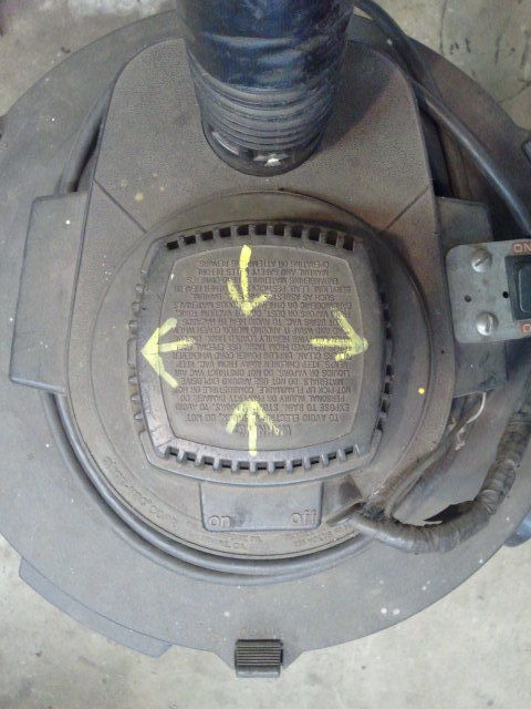
I looked at my flare blower again and it has the skinny impeller for the gas,and a second fan on the other end for motor cooling.I knew mine did not use the gas to cool the motor but had to look again to see how. 2 photo’s to look at.One photo backed up from unit just to show from a couple of feet away and the other looking directly into the cooling end.You can see the fan blades inside,they look kinda rusty looking.So you know I an not nuts. Also ran my shop vac and lit a piece of wood for smoke. I put my hose into the outlet for the filtered air, to get the air current away from my motor vent holes so as not to affect the test. 3 pics.
I marked on top of the motor housing with yellow paint marker to show air currents drawing the smoke in and blowing it out of the motor housing.This was independant of the suction fan inside.You can see in the last pic. that the inlet vents are higher then the exhaust vents. Dan

I guess if the gas/air mixture needs to be about 1:1 for the engine spark to ignite the charge it would take a serious system leak before it would go B O O M ! But at my age I learned to never say never. In my homebuilding days I remember using a Craftsman shop vac to do the final cleaning of drywall dust before primer and I remember the windings and brushes being caked with that fine dust that snuck through the filter - that is why I asked.
Don M
Hi Don,
Yes, you’re correct but remember the little fan is pulling in sheetrock dust laden air and that’s what is reaching the inside of the motor, I believe. After cooling the motor most of it exits at the same place that the gas exits. The rest stays in the motor. How does that dust get inside our cupboards, nostrils and lungs?
Pepe
i’ve made our small shop vac go pop a couple of time. happens when i shut the gas valve before turning the vacs motor off… it drags some air into the friction fitted hose coupling. its never been that spectacular and the shop vac still works.
Hi All, thanks for your comments. My vac motor has a small fan on it that draws in room air for cooling the motor and when it gets past the motor it joins the gas stream to be expelled. There is zero char inside the motor housing. Dan my unit works just like you described yours. It must have been a challenge building the unit. Your unit seems good sized also. The power of that small rotor amazes me.
Pepe