But does it have to be “perfectly airtight” or just “mostly airtight?”
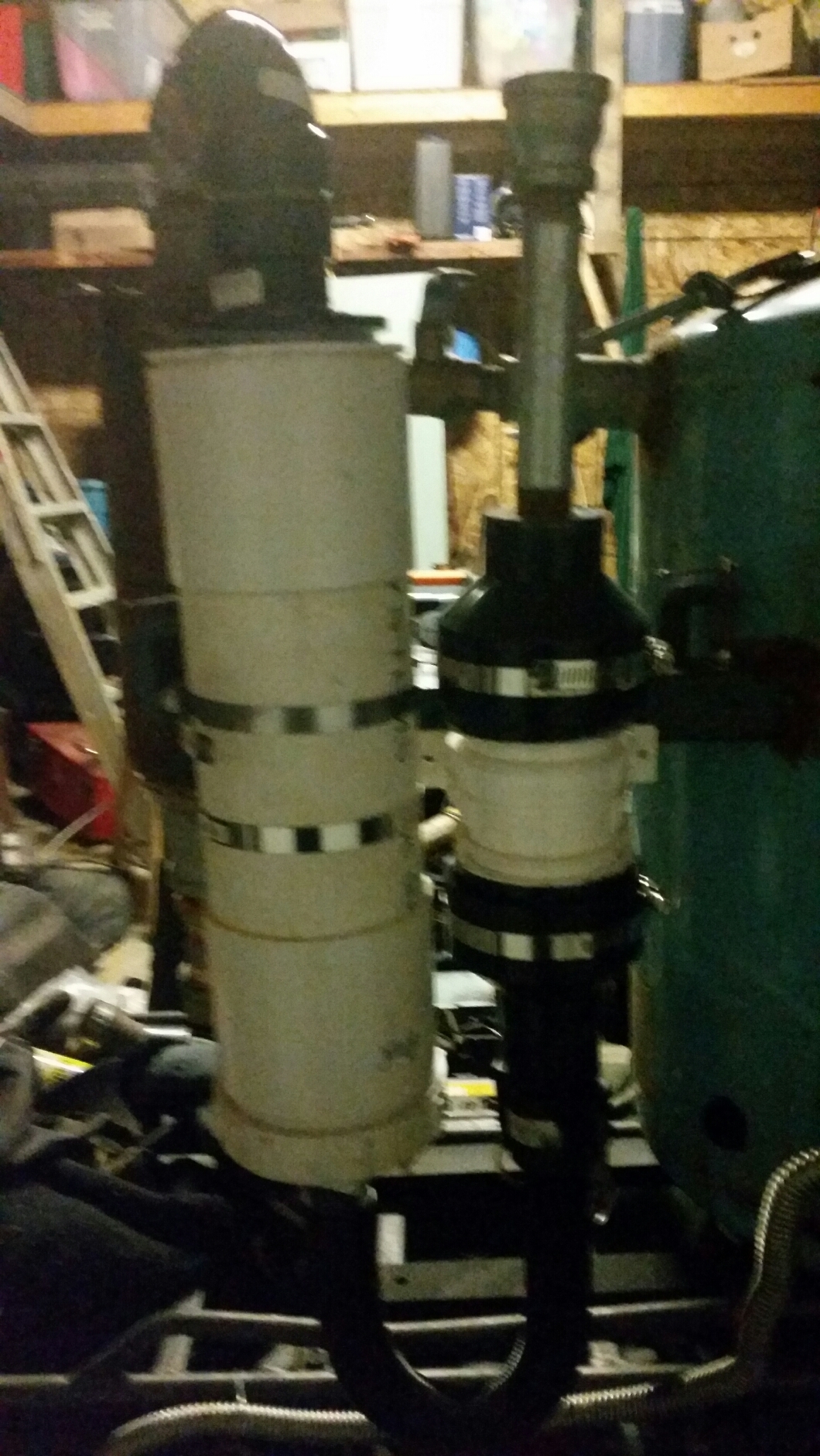
The reason I ask is that I noticed that if I blow into the hose barb pictured on the filter bucket above, I can force a little air past the threads of the Gamma Lid.
If this is going to be a problem, what should I do to stop the leak?
Once the gas has cooled below the auto ignition point, the air tightness is not quite as critical. Remember too, that what leaks under pressure may not under vacuum. A little grease on threaded connections helps without sticking them together.
Is this the lid you are talking about? http://www.gamma2.net/gamma-seal-lid.htm
If so where do think it is leaking, by the screw on gasket or where the flange mounts to the pail? David B said that butyl rubber caulk will adhere to plastic but not silicone and maybe that would stop leaks at the pail.
Air/fuel mixture has to be close to 50/50 to run an engine and a little air leaking before it gets to the engine will change that setting slightly without doing any harm.
3 Likes
ray_menke
(Ray Menke (Lytton Springs, Texas))
#124
I used some high temperature wheel bearing grease. Once you get the engine running, note exactly where the air valve needs to be set, and make a mark.
Hi Kyle , All parts of the system need to be 100% air tight at all times , just the slightest leak will give your engines different running problems from not being able to start too not being able to tick over, lack of power , also when flaring if you are having problems getting or maintaining a flare its always down too air leaks somewhere , normal silicon will work fine on the filter drums and hose fittings .
Dave
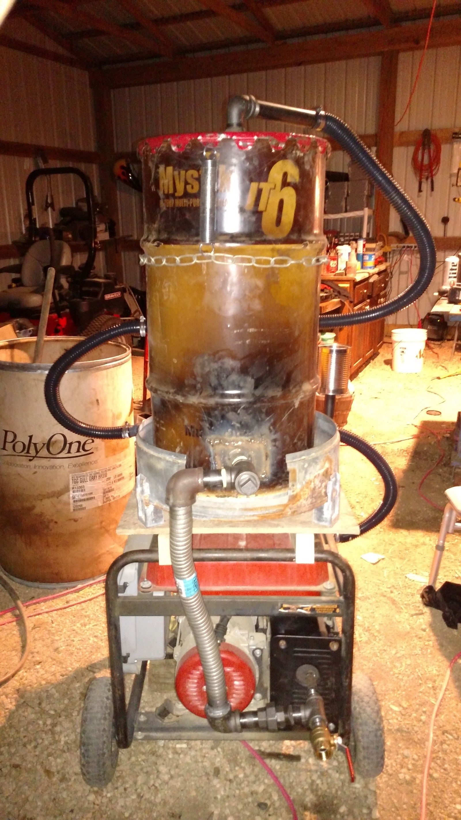
came in late yesterday afternoon. That was the last ordered piece I was waiting for. I was off today, and got to work on the project most of the day.
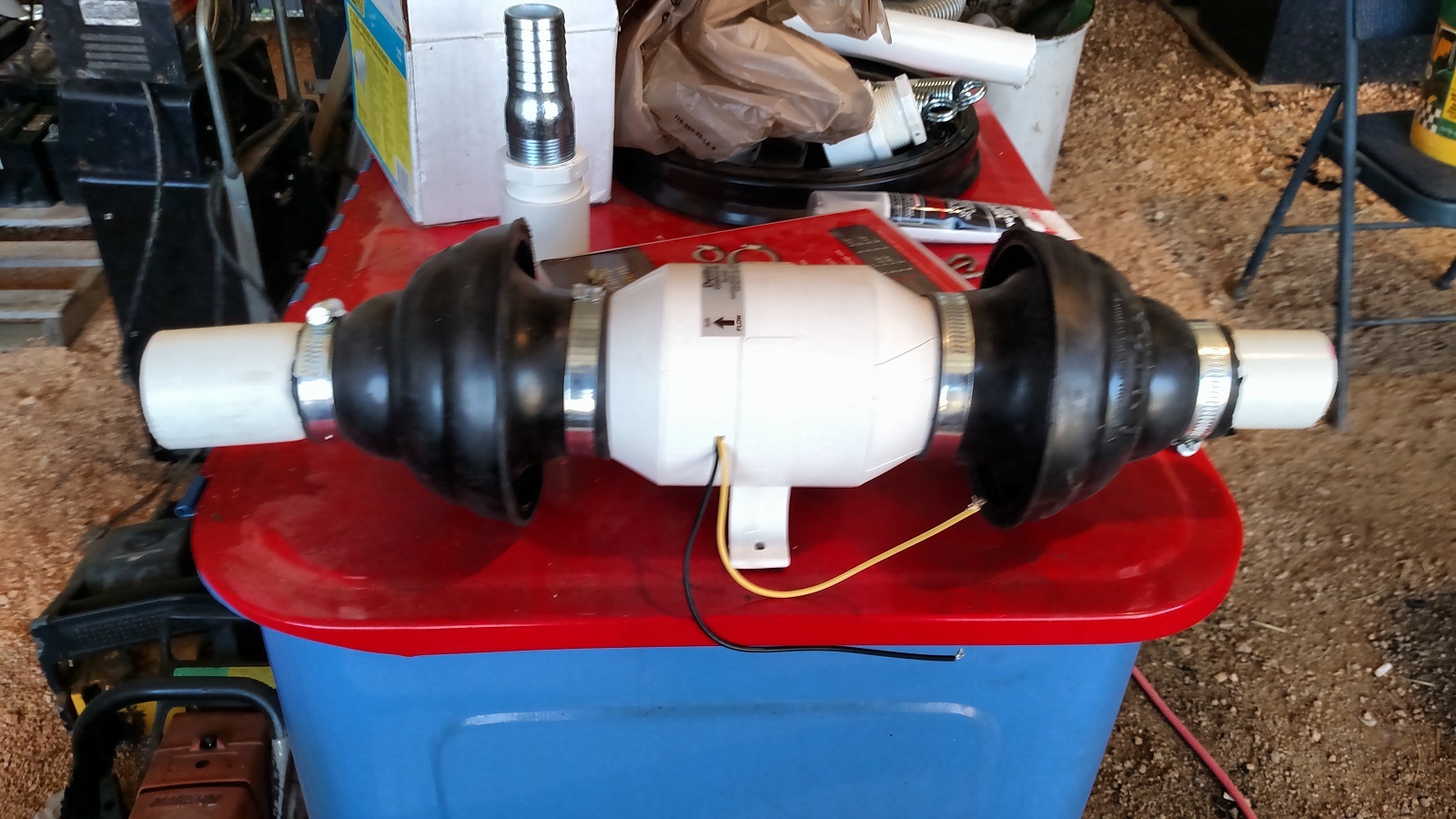
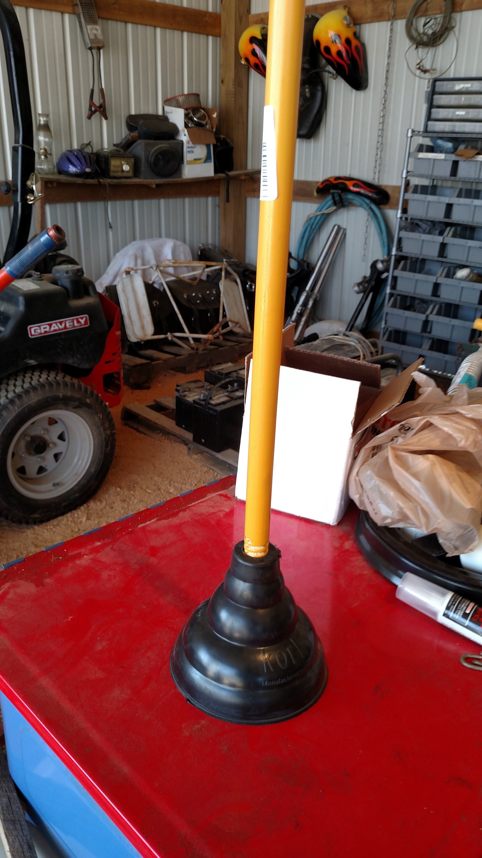
I hadn’t given much thought to how I was going to adapt the 3 inch blower to the 1.25 inch sump pump pipe. I just went to Ace Hardware and started looking for stuff. Anyway, don’t laugh, but this is what I came up with.
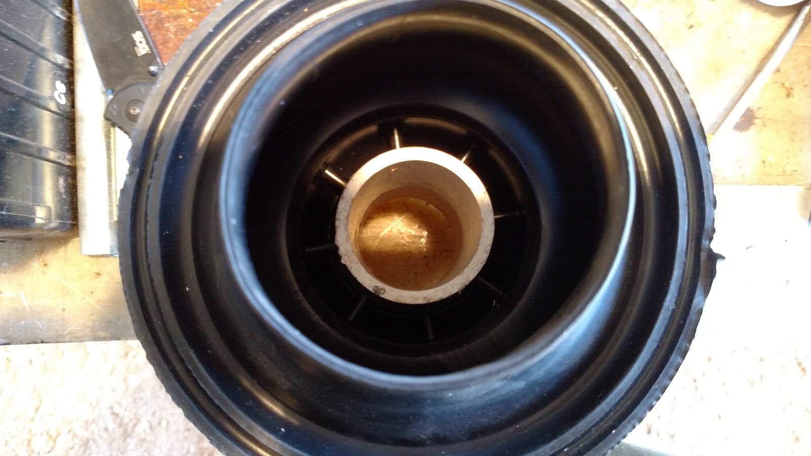
The stretchy rubber at the bottom of the plunger fit perfectly around the outside of the blower. And the inside made a nice tight fit to a piece of PVC pipe after cutting the handle end off.
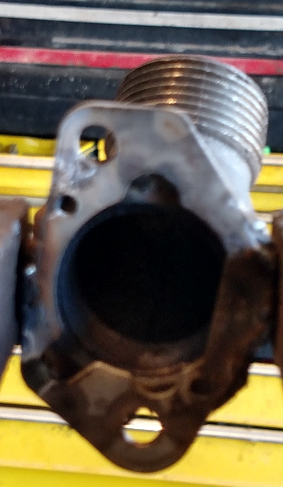
was the next order of business. I removed the boxy intake filter and found that it was held on with a little plate that I could remove. I found a 45 degree pipe fitting that I could weld to the plate.
Ended up welding 3/4" black pipe to the exhaust exit, then going to the tee assy, The return line is 1.5 inch exhaust flex soldered into some pipe fittings. Don’t know how well that will hold up.
sits on a quick-detach wooden frame that sits on the steel frame of the generator. The whole thing can be easily removed as a unit, if I want to run something else with it.
Don - Yes. That looks like my lid, except that it is black. It is leaking around the threads for the screw in portion in the middle. I will try a little grease or something on the threads.
Looking great kyle. Only thing I can see is you will need some way to meter the exhaust so you don’t choke off the reaction with too much CO2 return… good luck on flaring it.
Best regards David Baillie
I like the inventiveness… I got lucky and my blower fit a 3 inch abs coupler perfectly and I transition cemented it together. This is the atv unit, the fliter housing is 4 inch pvc with clean out ends.
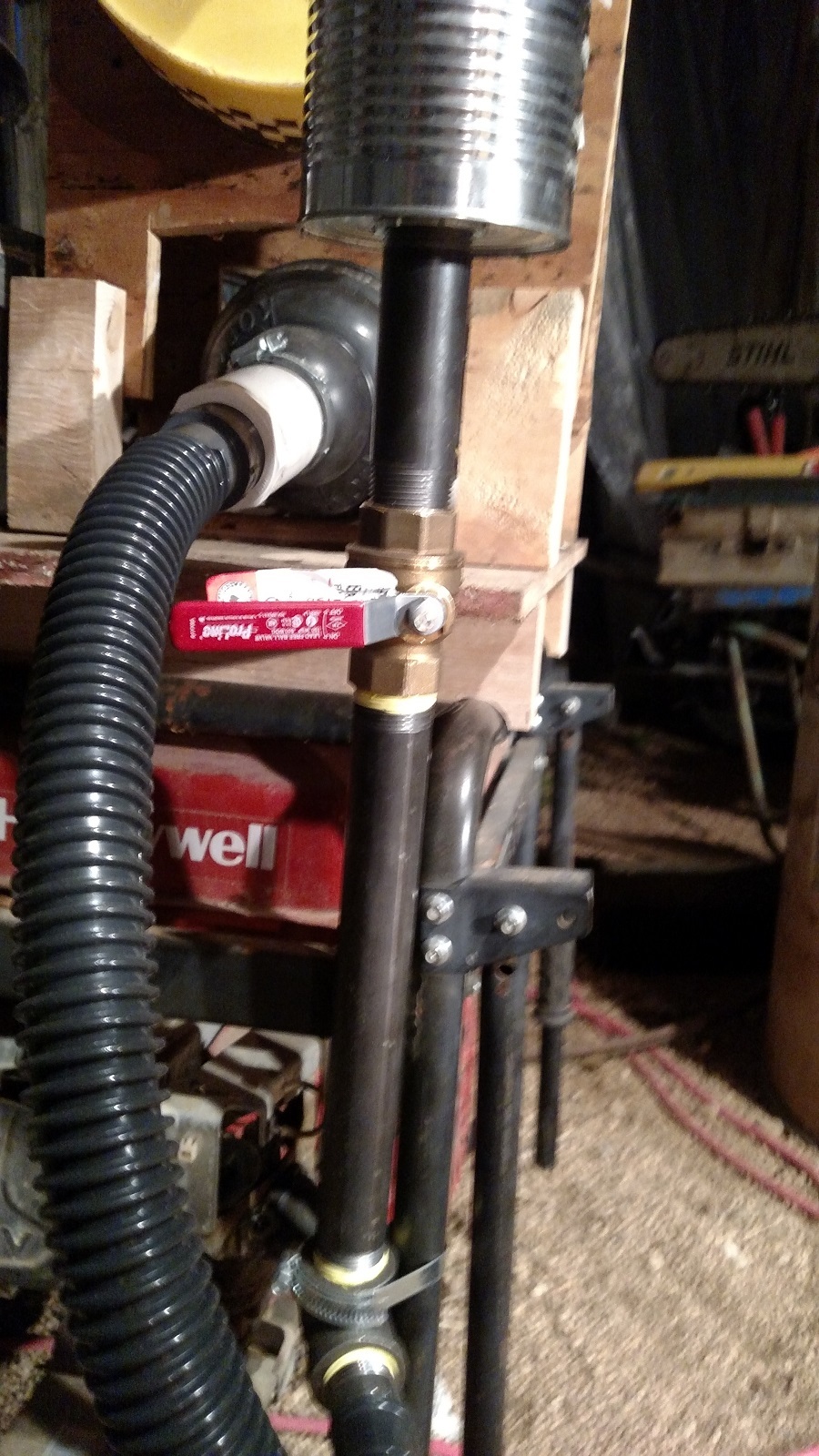
I was a little uncertain as to how to do the exhaust return metering.
I attached to the outlet from the box muffler.
It is 1/2" diameter.
I stepped this up to a 3/4" tee.
The straight-through path goes through a 3/4" ball valve, and exits.
The 90 degree path goes through the exhaust flex, and up to the reactor.
I was thinking that the exhaust gasses would prefer the straight through path unless I restricted it by partially closing the ball valve.
It did not occur to me that, even with the ball valve wide open, too much exhaust might go up to the reactor.
After seeing your comment, I went back and looked at Gary’s design.
It looks like he goes straight from the exhaust manifold to a tee, then puts the muffler on the other side of the tee. His metering valve is then placed in the exhaust return line.
I can see how his would work, since having the muffler on the other side of the tee would create some back pressure, causing the exhaust gas to prefer the route through the exhaust return line if the valve is partially open.
I am less clear what I should do to fix my situation. It would be easy enough to move the valve inline with the exhaust return line. But I am thinking I would need to put a reducing coupling or something where my tee is now, in order to create a little back pressure so that the gas would prefer that path if the valve is open?
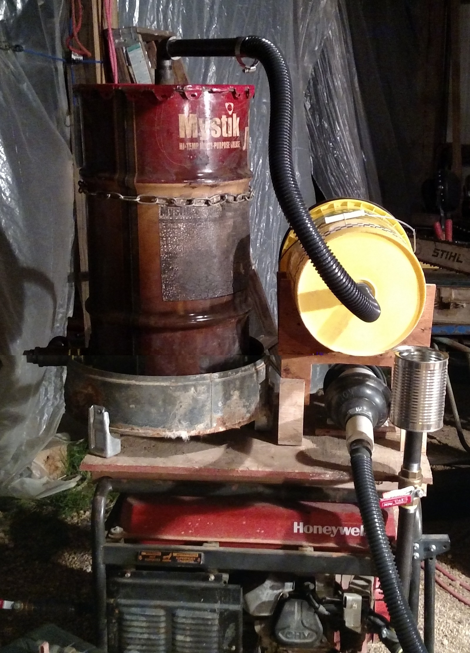
I was sitting here looking at the picture of this contraption, and I think I see another problem.
Gary had suggested using plastic components to mount to the carb to reduce the stress on it.
I used steel, but the weight is supported because the steel is attached to the generator frame with a band clamp.
It just dawned on me that the motor mounts (rubber pieces) allow the motor to move independently of the frame, and my setup will try to resist this independent motion, stressing the carb attachment.
I think I should go back and put a short piece of flex between the fitting on the carb, and the rest of the intake assy.
Kyle, I used a bicycle inner tube for a vibration damper on my charcoal lawn tractor. I don’t have a picture of it but it is shown in this walk around video.
@kyle one thing to remember: any time the engine is running, it’s sucking on the gasifier, which in turn is sucking on the intake (and exhaust recirculation). This suction/vacuum would probably overcome the momentum of the exhaust to go straight, or a little bit of back-pressure from a muffler.
Hey Kyle I totally missed the valve on the exhaust exit… should work . I used plumbing rubber connectors for vibration mounts. Don’s inner tube are cheaper and probably stretch a lot more.