Charcoal gasifier prototype for 5-7HP lawnmower engine

I upgraded my firebrick with a tungsten carbide nozzle, (a size 5 wedding ring) and I also mounted a thermocouple inside the reactor to gauge the reaction temp. The ring has curved sides, so it fit perfectly into the 3/4 hole. I cemented it in with a little furnace cement.

When I opened the reactor today the lid had a considerable amount of moisture condensed on it, so hopefully the brick has been more or less dried out now. I am keeping my charcoal in a sealed bucket, but I suspect I am going to have a hard time keeping it completely dry in this climate. I looked inside my filter and did not see any dust or soot in my batting, so that feels hopeful.

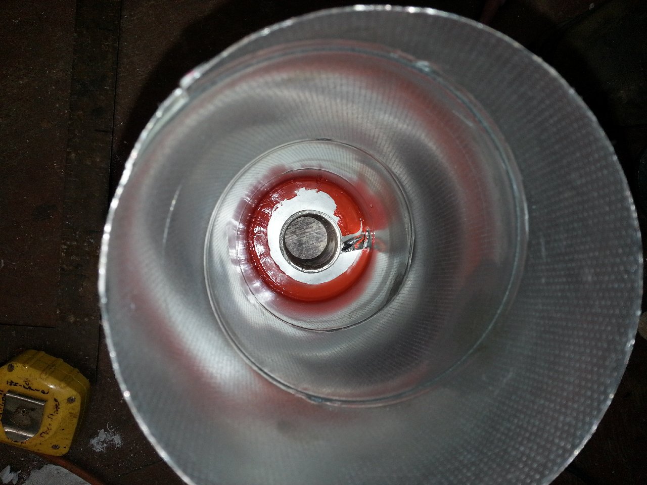
I also tore down the blower I had built, and added 4 more vanes to the rotor.

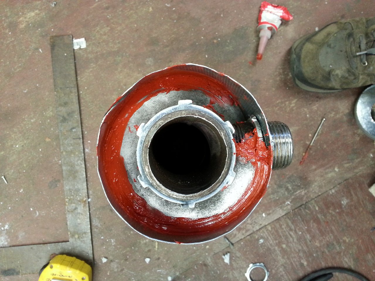
This appears to have increased the suction by quite a bit, so I think this setup is actually going to work. The gearbox leaks oil like a seive, but since it will get so little use and at such low RPMs I am not too concerned. I painted the parts, because now that I have put so much time into it, I might as well make it last. Once the paint has cured I am going to seal all the parts when I re-assemble it, as I am more than a little bit paranoid about CO leaks.

I redesigned the manifold for the gas intake, and will mount it to the generator frame to take some stress off the engines intake tube.

My goal is to try and make a system that will be fairly easy to adapt to any engine, as the one I have is going to be really hard to implement a governor on (since it has no carb). My thinking on the manifold is:
Red valve is the throttle,
Blue controls air intake,
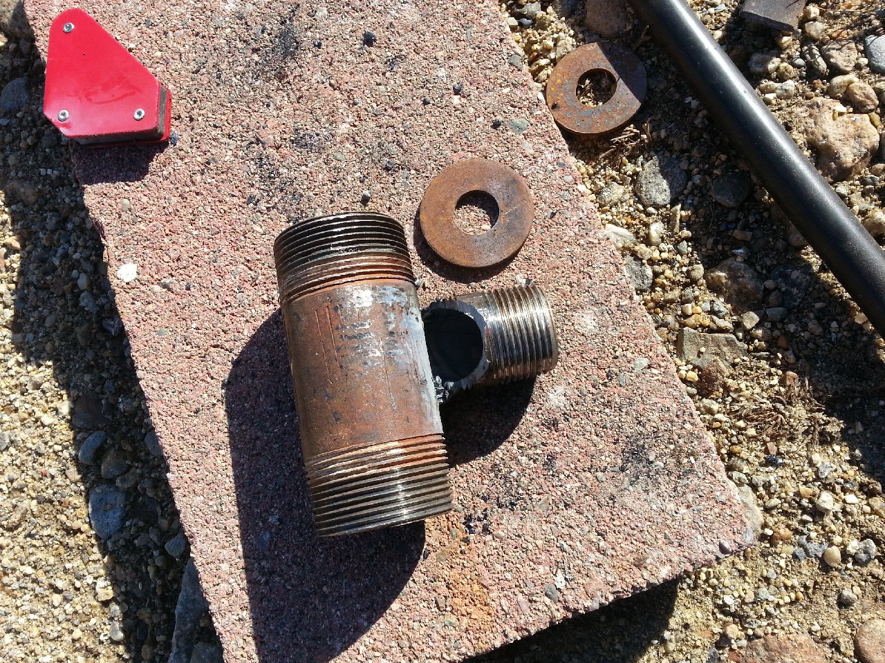
Ball valve goes to the blower - I brazed a short threaded section on to my blower housing, so it will mount directly to the manifold.

Opposite the throttle will be the gas intake from the reactor.

I do have a quick question about alternators - and that is can they be spun up with no load? Could the regulator be damaged if the RPMs get too high and create a higher voltage than it is rated to handle? @SteveUnruh : you are a bit of an alternator expert, are you not? Any thoughts?
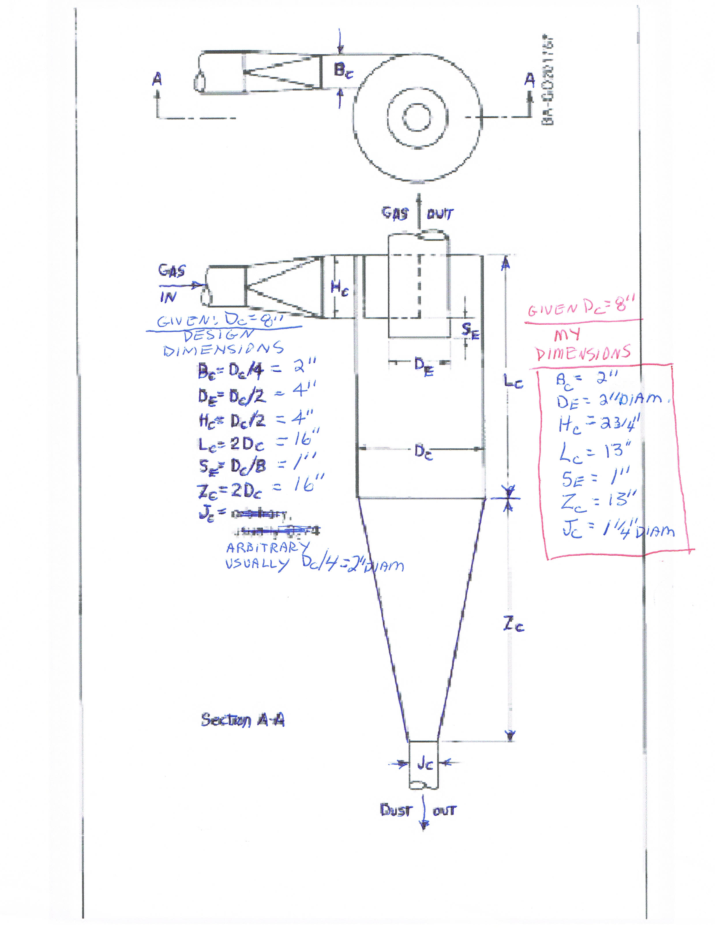
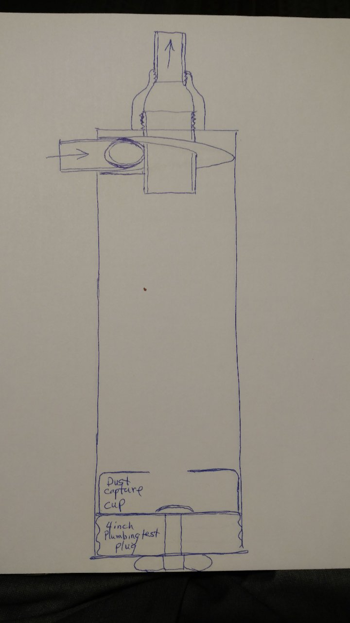
2 Likes

Iā€™m enjoying the pics and great descriptions. Keep up the good work!

Hi Carl,
Welcome aboard. Hereā€™s a video that details a cyclone build. Iā€™m not quite sure about sizing to your HP. Iā€™m also not sure youā€™ll need a cyclone for a charcoal gasifier, someone else will have to chime in here.
I also have a final filter before the carb inlet. I use pine needles covered with a paper filter before the filter outlet.

Hereā€™s another I built for my line D sized imbert design ( 45 HP ). This thing is BIG, but it shows how effective the design is.

This can be scaled down ( I had an 8" tube hanging around ), itā€™s the proportions that are important. Some will say the cone is not necessary, I disagree. A little difficult to fabricate the cone, but the results are really worth the effort. Besides, itā€™s neat knowing how to fabricate a cone.

Pepe

2 Likes

I agree with Pepe that the cone is important on the cyclone. I donā€™t feel up to the challenge of verbalizing the reason, so I include this link to do it for me. Also a cool video of a clear cyclone for your amusement.
http://www.floweringelbow.org/projects/the-cyclone-dust-separator/cyclonic-dust-separator-overview/

1 Like

Andrew, Thanks for the link to the video, very interesting and informative. A picture is worth a 1000 words.

Hi OrCal
Normally Iā€™d say on automotive alternators there is no problem spinning them up not attached to a battery. The real problem for all is disconnecting the battery/buffer while they are loaded charging being spun up. Voltage then does spike heavily loading the normally intalled surge/buffering capacitors. Once those capacitirs blow then you will wipe out the regulator electronics and/or some of the power switching diodes.

Not a problem for most alternator/regulator systems as the power to get them operating comes from the battery fed/controlled by the voltage regulator to the spinning rotor/field coil.

Yours however is a GM/Delco Remy ā€œSIā€ based unit. These have separate internal field power supplying diodes (Delco-speek, a diode trio) like many late 60ā€™s thru 70ā€™s designs from Robert Bosch, and others of that era. They are intended to self-excite and supply their own internal magnetic field power.
Best to just hook up some type appropriate voltage battery. Load not needed.
regards
treeā€“farmer Steve Unruh

2 Likes

Well, I got everything put together today, and figured I would let the silicone gaskets cure overnight. Yeah right. I cleaned up the shop a little, tightened all the bolts, and then said, ā€˜screw it, lets fire this thing up.ā€™

Here is a video. It was really easy to get a flare going with my little hand-cranked blower, what was not easy was figuring out the right number of turns on my valves to get the engine to actually turn over. In hindsight, I should have been a lot more systematic, but half an hour later I stumbled on a ratio that seems to work: 3.25 turns on the air, .75 on the throttle. And away it goes!

I have ordered a tach to help me dial in the idle, but I think I am going to need to make a few modifications first. With the engine pulling, my reactor thermocouple was registering over 2300F (1260C)! it is only rated for 800C, So I hope I didnt melt it. I might try moving it up higher to get it away from the hot core and I suppose I am also going to have to implement EGR. I also saw a puddle of water forming at the bottom of the hose coming from the reactor, at the filter inlet, so I might add a thin-walled cyclone onto the reactor to try and catch some of the water vapor.

Thanks for the input Steve, I have a couple of 12 volt 35AH SLA batteries that I can connect in series and hook up to it- that should work, right? I am going to mount a panel to the side of the generator for a multimeter, tach, and the kill switch for the engine.

And thanks everyone for the input, I will definitely check out that video about the cyclones.

7 Likes

I agree that a picture is worth a thousand words. That is why when I first read about cyclones working in a cylinder without cone shaped walls, I had to build one out of a clear lucite cylinder and run tests with charcoal dust. Seeing is believing!

Also, if you use a spiral air ramp, the tangential entry is not necessary. The inlet pipe can be cut off at an angle and entered straight into the side. The spiral air ramp creates the spin.

I have found this alternative geometry easier to build and very effective. There are actually two ā€œcyclonesā€ in this cylindrical arrangement. The central one that is cyclone shaped and the other which spirals down along the outer wall of the cylinder. The dust that descends along the outer wall comes to rest on the bottom and is then pulled in by the central cyclone and deposited in the collection chamber.


Note that the larger diameter exit pipe slows the exiting air speed so fewer particles escape. The one inch exit mentioned above will work, but it is better to exit with 1 1/2 inch then reduce down to 1 inch.

Also note that this last picture was taken before the lid was installed.

6 Likes

I would like to see a cross section drawing of this Bruce. Very interesting.

5 Likes

I second Mr Don ! !

Marry Christmas !

2 Likes

I was thinking about the EGR this morning, and went back and looked for a picture I remember seeing (simple fire post 33):

So, @glgilmore : I realize this is an old idea, but is it still sound? I notice there is no valve on the exhaust return line, either. Is that something that should have been implemented? My muffler not being threaded makes me think this is going to be the easiest way to keep things simple. What are your thoughts?

I hope everyone has been good this year, and you all get some charcoal in your stocking! Happy holidays to everyone on DOW!

3 Likes

Don & Jeff, Here is my current favorite small engine cyclone based on my research and clear cyclone experiments.

Carl, yes you need a valve for EGR, but use a multi-turn gate valve instead of a ball valve for better control.

5 Likes

Oh, yeah, I use electrical lock nuts to fasten threaded pipes to the thin wall duct pipe and stove pipe plug lid. Seal everything with RTV. Notice in the photo above that I weld the 1 inch to the 1 1/2 for stability and alignment.

2 Likes

I like it. It is so simple of a design. Like the dust trap at the bottom. Thanks for sharing Bruce.
Merry Christmas to you and your Family.
Bob

1 Like

Bruce, that is an excellent Christmas present you gave us ! ! Iā€™m sold. Iā€™ll add a sock filter on top.

2 Likes

Pruning has started up on the vineyard, so I have been trying to not spend all my time in the shop working on my generator project. The frame I built was starting to get covered in rust, so I slapped some paint on it, and now it looks pretty sharp. I got a free engine off a trashed old lawnmower that my brother had found somewhere - this one is a Honda OHC, and still has its carb.

I got it mounted to my generator frame today, and built an adapter to connect it up to my manifold. It was going to be a pain to implement a governor on that B&S flathead that I started with.

I also had been thinking about what people had said about using a drill to start an engine instead of the recoil start, but I did not want to damage the drill once the engine catches, so I put together a little 3/8" drive ratchet.

I cut the head off a crappy old ratchet that I got at goodwill, and then brazed on a short section of pipe with a piece off an old socket. You can buy something like this, but it cost like 40 bucks. I will probably put the pull rope back on at some point, as I feel like simple is best - but for testing this will no doubt save some frustration.

Next up is EGR, then I should be ready to do a few more start-up tests.

8 Likes

I have been looking for a ratchet, 3/8ā€ drive to serve as a starter.

Voilaā€¦ you built one!

Now why didnā€™t I think of that
Thanks

1 Like

Bruce,
I like your vent pipe cyclone and using your ideas will try to build a totally no-weld version. Electrical lock nuts are the only type of pipe thread nuts available here locally, but I have found that black iron pipe lock nuts are better and have started to use them where I can. They do require a little more space, however. I have bought those and most of my other pipe fittings and nipples from supplyhouse.com. Thanks for the cyclone ideas. Also, I have seen high-temp aluminium tape and thought of adding that to the outside of the pipe seam in addition to filling the seam with high-temp RTV compound.

Great overrunning clutch development OrCarl.
Two other that could be utilized would be an actual out of an vehicle engine starter starter/gear drive unit. Nippon Denso offset spur drive units have this as a self supporting unit.
10 speed bicycle rear wheel hubs have an overrunning unit in the gear cluster.
Regards
tree-farmer Steve unruh

3 Likes

Steve,
So thatā€™s what they are called! I have bumped into those stronger pipe thread nuts, but didnā€™t know what they were called or where to find them. Definitely better for tightening and heat resistance. However, I have had no problems with steel electrical lock nuts and they usually have a curved shape which helps to conform somewhat to round vessels. Their tabs make them easier to tighten in tight spots using various punches, chisels, drivers, pliers, spanners, etc. where regular wrenches donā€™t fit. There are some electrical nuts that are cast from a softer alloy that donā€™t bear heat well. I use spiral duct that can be ordered from home depotā€™s online store. Comes in 5 feet lengths in various diameters. Strong, true round with solid seams and smooth interior.

1 Like