Thank you,
54.5vdc / 24 cells
Sounds about normal for a lead acid bank.
Thank you,
54.5vdc / 24 cells
Sounds about normal for a lead acid bank.
I feel like I am missing something. You have solar panels and a charge controller correct?
If so let the sun do the ballance charging on the next fully sunny day. If you can only charge the batteries partly with the generator all the better it will leave capacity for the sun come morning. You don’t want to max the batteries out on a generator it wastes fuel you have to pay for or work for if it is wood.
Thank you,
What you are missing is two scenarios, and the difference in battery chemistries.
1.) Monsoon season. 4 months of diminished solar activity. Your equivalent of winter.
2.) Maintenance charging / Battery equalization. The need to periodically over charge the battery to prolong the lifespan.
In the case of Lead Acid people, mitigate Sulfation. In the Nickel cell world it is to reverse the phase change that occurs in the Nickel plate. What is termed as Nickel cell “memory”.
I don’t know what it is for the Lithium folks. But I hear they have similar requirements.
The gen heads I have are engineered around lead acid requirements. Which is the “industry standard”. ie 12 / 24 / 36 / 48 volt systems all evolved from the design limitations imposed by a 2.7vdc lead acid cell.
I am trying to match 1.2vdc cell battery bank load to a 2.7vdc derived generator head.
One that I am not familiar with. So, I decided to err on the side of caution and ask questions …
For those of y’all who have experience with DC generators … particularly those who have run PMG dc generators … either in charging or direct loading applications
What happens to the generator when the starting load resistance is lower than expected? In the short or long term?
What if that resistance is half of what the generator head is designed around?
There are a lot of different ways to explain this. The simplest way is to say that as resistance decreases, amperage increases. With increased electron flow (amperage) comes increased heat.
The real important question is:
How many amps can your gen head deliver at 100% duty cycle? Meaning what is the safe number of amps that the gen can make continuously?
The secondary question is how many amps are safe to deliver to the batteries?
I cannot speak to your batteries.
Lead acid batteries don’t need a voltage regulator until they get into the 14volt DC (per 12vdc batteries) range. They do need amperage control. I simply charge mine with a genhead that cannot deliver excess amperage.
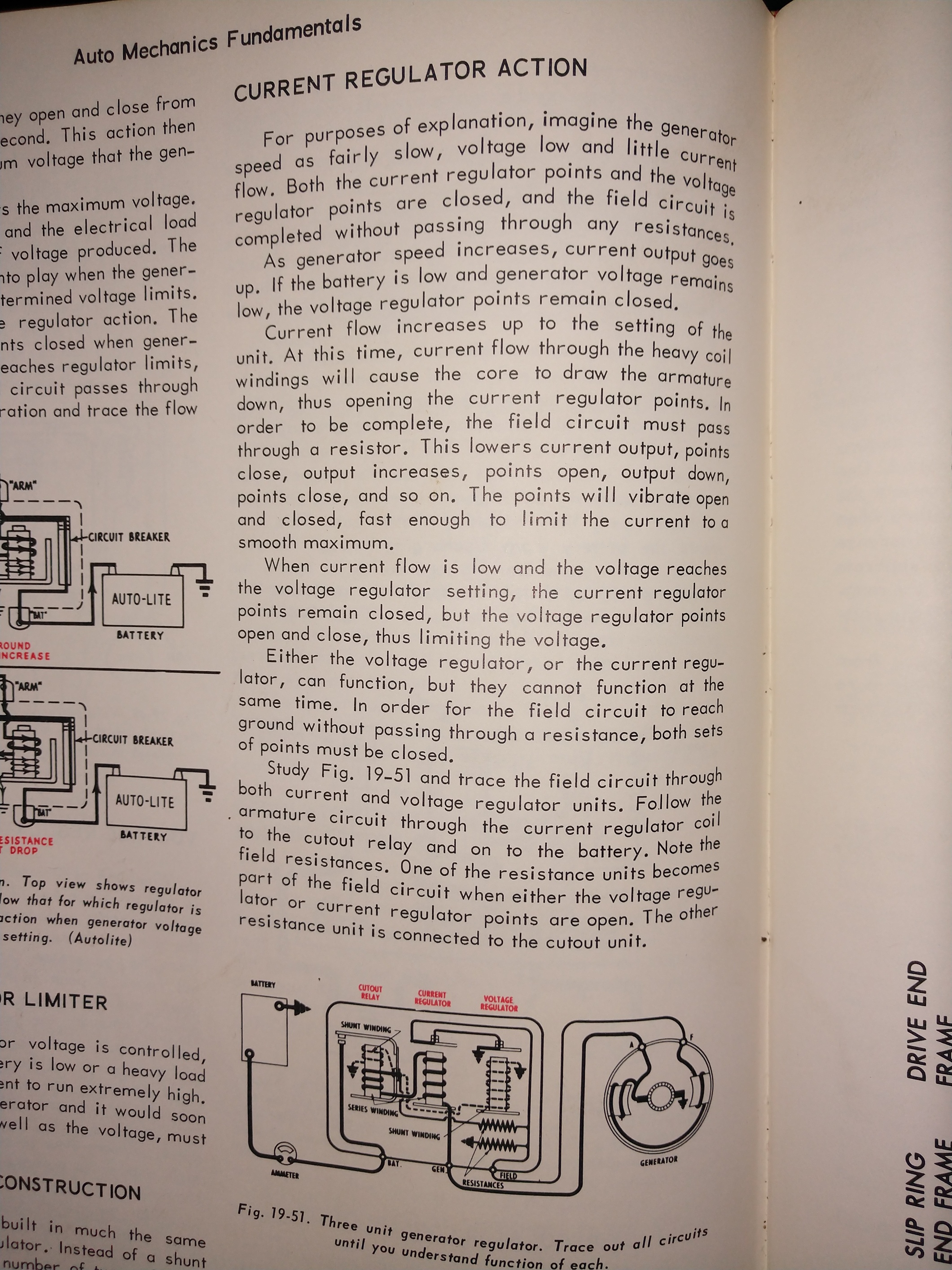
The old automotive generators used a amperage regulator that used a relay whose armature was magnetized by the total current flow. The points were opened and closed by a spring working against this magnetic field. Very simple, very effective. This might be good for you too, as it’s completely repairable.
I apologise if I am talking down or am failing to explain properly.
Thank you,
Let me noodle on that very carefully. Maybe add more later.
If I go by the gen specs, then it can deliver 100adc continuous duty. I am aiming for 70adc for the length of the charge run.
My NiFe bank is rather large. According to the manual a standard charge rate is 200adc.
This is simple then. The gen will max out it’s amps. It will try to give as much as it can to bring it’s voltage up. V=I•R The gen thinks it’s voltage should be V but the battery bank is lower then V. That’s because the battery’s internal resistance R is down. As soon as the battery’s voltage comes up, the amps cascading into the bank from the gen, will taper down.
If the bank can take it, then the weak link will be the stator wires in the gen head. They get hot and melt their insulation off.
Frankly, I know more about how non PMA alternators and generators operate. Because the voltage stays down, when charging, the fields never shut off. This means the stators or armatures never get a break. A continuously powered field winding will build a greater magnetic field then it’s rated for, which in turn makes greater amperage in the stator or armature. This means a non PMA gen can output a tremendously greater amount of power then it’s rated for, at the expense of a much shorter life span.
I suspect your PMA will not do this. It has a fixed magnetic field which limits it’s amperage output.
Thank you VERY much.
“The old automotive generators used a amperage regulator that used a relay whose armature was magnetized by the total current flow.”
Problem is finding one that is rated at a high enough dc voltage, say 70vdc, and the appropriate amperage, 100adc.
" then the weak link will be the stator wires in the gen head. They get hot and melt their insulation off."
I was thinking more along the lines of letting the “magic blue smoke” out. But yeah exactly.
“It has a fixed magnetic field which limits it’s amperage output.”
I wonder if the engineers that did the design were astute enough to set that value at the stated 100adc specification?
“amperage control”
If memories of my test run serve, I had rudimentary amperage control via pto RPM’s.
The single sheet printout “manual” that I received was adamant about not exceeding 3000 RPM’s. That would match the function of a fixed magnetic field.
The 3000 rpm may have something to do with the glue holding the magnets on the rotor too.
That may be your simplest solution. Simply govern the engine.
An automotive generator regulator could be used , but probably not as intended, and therefore would not be the simplest solution.
It would be interesting to graph the open circuit voltage through a range of rpm.
Yup, I like it. Clamp down the rpms on the engine. I think this safest for the generator.
“It would be interesting to graph the open circuit voltage through a range of rpm.”
I can do that. Good idea.
You and Steve are the heroes of the day. Thank you.
As you say it has electronics to control the voltage output, But it is possible to modify the AVR to output the voltage you need. I doubt that 10 more volts out would hurt any components. Check your adjustments on the AVR to see how much swing you have. That may solve your problem. Go slow and check the board for temperature rise so you do not damage it. If you do not have any adjustments on the board then component changes will be necessary. If you still have any kind of warranty this method will void it for sure.
Thank you,
I opened the top enclosure and looked at the inter-connections. I do not remember anything that looked like a voltage regulator. It may be mounted in the case with the windings.
I like your idea. If I can find it I’ll cross some of the component designations, try to discern viable limits. That and look for adjustment points.
What do you think of running a pmg gen head with a high side cut-off of 58.5vdc on a 24vdc battery bank?
The main culprit for failures with PMG is the temperature for the magnets…
Those with Neodym demagnetize at low temperature… they are strong and good at low temp, but once they exceed the minimum car engine temp, they loose their magnetism…
Interesting your statement that PM magnets strength varies with the magnets temperatures.
I’d never thought of that. Cannot help but be true.
Only long term wide range of temperature use I’ve experienced with PM magnets has been in vehicle starters for the last 30+ years. Bocsh were the first I encountered. Then GM/Delco. Now, almost all.
They’ve seemed to work fine in sub-zero, to hot, hot heat soaking. Maybe fine in sub-zero because of increased Mag strength maybe, eh. Cranking starters only have to burst produce.
MarkC. most of us gave up on PM generators for battery banks because of lack of controllable field strengths.
Your only true “simple” control is engine RPM. The engine driven inverter-generators systems using PM’s are a whole other world.
A single just starting battery can be plates resistance and thicknesses designed for a PM’s wild voltage and amperage.
Wife’s rider lawn mower battery was weak from non-use for nearly 2 months.
A commercial U1 lead acid. I jump started it just fine. Then had the dickens of time convincing her she had to engine run at a full 3600 RPM to get it mowing charged back up. Her preferred putt-putt 2400 RPM the engines PM charging coils will not high enough voltage produce to charge it.
I can hardly charge it with the remote battery charger only on Boost to get 15+ volts forced in.
It was intentionally designed for the engines PM chargers high full RPM voltage to not heat boil damage. That system by it’s nature is current limited.
Sorry. You will have to become an engine RPM master controller using this PM unit, imho.
Regards
Steve Unruh
Did you really mean “58.5” volts into a 24 volt battery? That seems quite high to me.
Thank you. Uhmmm yeah I did.
58.5vdc is the mfg stated maximum for my gen head in question. I am pretty sure I can hold a lower charge voltage at lower rpm’s
I am contemplating this for physical reasons. Matching my bank resistance to the gen head by manipulating the number of cells under charge leaves some cells un or under charged.
Perhaps, I am able to neatly split the big bank into two equal smaller banks and charge them.
1 - 40 cell bank into 2 - 20 cell banks. Each with a nominal voltage of 24vdc. Ending, charged, target voltage would be 33 → 34vdc.
If Steve’s mower analog is apropos, then lets say I have to drive 1.8vdc for a total of 36vdc.
Once the drizzle lets up, I am going to follow DualFuel and chart out volts to rpms open circuit.
Maybe there is a charge plateau that I can maintain via pto speed. Try for 36vdc @ 70adc out of the pmg at say 2130 rpms , (just pulled that number out of my butt).
Hopefully without melting insulation, pulling magnets out of their mounts, or otherwise letting the magic blue smoke escape its containment in the generator head.
An additional question is … Okay let’s say that I CAN achieve a decent charge. Is that gonna do a Koen swan dive, dip, sag, or other wise droop when the neodym’s in the gen head heat up? And how bad.
What do you think will happen, short or long term, if I try to chewing gum, baling wire, Bondo this ill fitting mess together?
I am a little reluctant to post my opinions, because I must confess my understanding of permanent magnet generators is not as good as it ought to be. I do have a bike generator that uses a PM generator, and when connected to a battery (through a diode) the voltage it puts out is limited by the battery voltage. Your gnerator is rated to output 58.5 volts, but it will not be able to if it given a big enough load (your batteries).
I dont think you are going to need to “dial in” the right output voltage by adjusting the engine speed. It sounds like the bank is plenty big to handle the max output of the generator - so as the engine throttles up, the voltage will climb first to the battery voltage. After the battery voltage is exceeded, current will start to flow relative to the resistance of the battery bank. Assuming that resistance to be fixed, Ohms law (v=IR) says that for the voltage to rise, the current also must rise. Current times voltage equals power, so the prime mover has to supply more and more power to keep driving up the voltage. If your generator tops out at 58.5, then it seems like it will just stop charging before it gets to 100% SOC. This would not be a problem for the generator, but as you note, it would not be ideal for the batteries.
If you can easily rewire the bank into a parallel 24v system, the bank gets a bigger capacity, and you drop your target voltage down into the range your generator can actually produce. Again, it can only produce that voltage if it is getting enough power from the prime mover. I think you said you are aiming for 36v volts (1.8v/cell), and the max output was 70 amps, right? So you would need to supply 2520w or about 3.5hp (before losses) to the generator head. This means it should be able to drive the voltage high enough to equalize the bank - but also due to the size of the bank it would not be able to raise the voltage too high. All those cells in parallel are going to be very low resistance, and once you exceed a certain voltage per cell you start hydrolyzing the water in the electrolyte anyway. That is why all those old school chemistries need to keep getting refilled with distilled water.
As for overheating the generator, it is the amps alone that determine the heating - so stay within the spec of 70 amps or whatever it was, and it should be fine. Obviously, halving the voltage is going to halve the power that you can deliver, so your charging is going to take twice as long.
Anyway, hopefully some of this is helpful, I think I need to brush up on the theory of PM generators a bit myself.
Thank you Carl.
CGG told me that a 10hp motor was needed to drive one of these heads.
Ok tractor Guru’s. How many horse power are available on the pto of an Iseki 22hp tractor?
Iseki is the Japanese company that acquired the Bolens line of tractors. My particular one is damn close to a Bolens G242.
I think 10 HP is probably more than you need. Without know the particulars of the generator let us assume a 50% efficiency. A 7 shaft HP to to drive the load sounds reasonable.
The PTO on that tractor should be good for half the engine power minimum, it wouldn’t make sense to have it rated at much less. 7 to 10 PTO hp to run something like a mower again sounds reasonable.
I don’t think you have any worries about power.
I am going to read this thread over a few more times later and share some thoughts on the electrical end of things.
Two banks of 20 cells.
Max charge voltage through the stack at 36 volts ( tune by engine RPM )
This all seems pretty easy you just need to tinker to get to work right.
You need to find the manufacturers recommended charge rates are and work around those numbers.
Those type of battery hare pretty resilient, If worked with Ni-Can and handled a Ni-Fe batteries but can’t offer much help because I would need to know a lot more about them.
I do know you want to use some cell oil in them to protect the electrolyte, and that means do not screw around and mix air in them with a Hydrometer ( once you have your S.G. mixed there is nothing more to do unless the electrolyte activities from CO.2 in the air.
Depending again the manufactures advice there will be situations where you need to make an equalization charge and occasional hard and deep discharge and recharge cycles to clear any Cadmium whiskers off the plates.
Adding PV solar cells to maintain your batteries would be a very good idea because these self discharge over time.
Carl mentions amps cause heating of the generator.
He;s absolutely right I think I would try the machine at 70% rated peak current at 70% rpm as a max and then test and monitor the temperature of the windings to make sure you do not over heat the unit.
I am making an assumption because is a small machine its going to radiate about 40% of its and that’s not a variable but air flow at lower speed is.
PM generators are pretty simple, they generate an AC voltage that is a function of rpm. Voltage should be linear, at least unloaded. In reality the head voltage will sag into a load because of wire resistance and at higher rpms because of some second order effects in the coils.
They aren’t great for direct battery charging because once the gen head hits the charging voltage for a given bank, the torque working against the engine and the current into the batteries will rise very quickly. This is because they have a fixed field strength.
The downside of PM gen heads can be addressed by a bit more electronics to down convert the voltage and manage torque. This lets the engine rev higher where it is more powerful and efficient not unlike what an inverter gen would do.