Yes, that will narrow the oxidation zone down. Make the nozzles threaded and adjustible. Same with the grate, adjustable up and down, to be able to set the reduction hight. And a loose fit changable restriction.
1 Like
My grate is made out of 8mm SS plate with cuted slots and going to be mounted to a shaft so it can be rotated or shaken that way, but it should not be a problem ajusting the height of it on the shaft.
I have a few SS heavy flanges that I plan on using for the restriction.
1 Like
I think you wuld get best resaults with a grateless and hearthless design. Here, the only direct heat/metal contact is at nozzle tips and restriction. Allso, l think you will be fine folowing the dimensions of JO’s gasifier useing chips. His gasifier has to make clean gas at idle, while your geny will never idle so no danger of tar
2 Likes
Kristijan, you might be right about the tar. Maybe constipation is more likely. A good grate shaker is a must on a stand alone.
3 Likes
Kristijan since I dont get any help from a moving car that drives over bumps I feel that I need to have a grate that can be shaken or rotated, when it comes to the nosles they can be changed to the lenght that I need since they are threaded in place.
1 Like
I would follow @gasman with his grate design using inverted stainless angles, ash protection above, large radiative surface below seems the best design.
3 Likes
Could not find any pictures or drawings of this,
Very simple Roger. Ss angle irons about 1/2 inch apart. Tips pointing down, grooves up. Grooves will get filled with ash for heat protection.
However I don’t think grate design matters much as long as it’s a bypass grate. Mine is pushed up into the reduction tube. It’s bit picky a deserves some attention. Not to recomend for a stand alone.
1 Like
Yes this is why l recomended grateless design above. it is not prone to constipation as the updrafting gas motion sifts ash and fines out of the reduction char, bridgeing culd be best salveged by connecting the hearth and the motor with a stiff metal connection.
1 Like
Aha now I get it, to use the ash as a insulator. I like that idea.
Im going to rotate the grate and have a seperate shaker, this is to get some char from the gasifier as a biproduct for the soil here on the farm. With long hours of production like Im planing it should produce quite a bit of char too.
4 Likes
I agree with JO that the grate design in not critical. But they talked about Max’s design with angle iron grates to hold ash. It is a simple construction but a couple of important parts to remember; My version of Max’s grate;
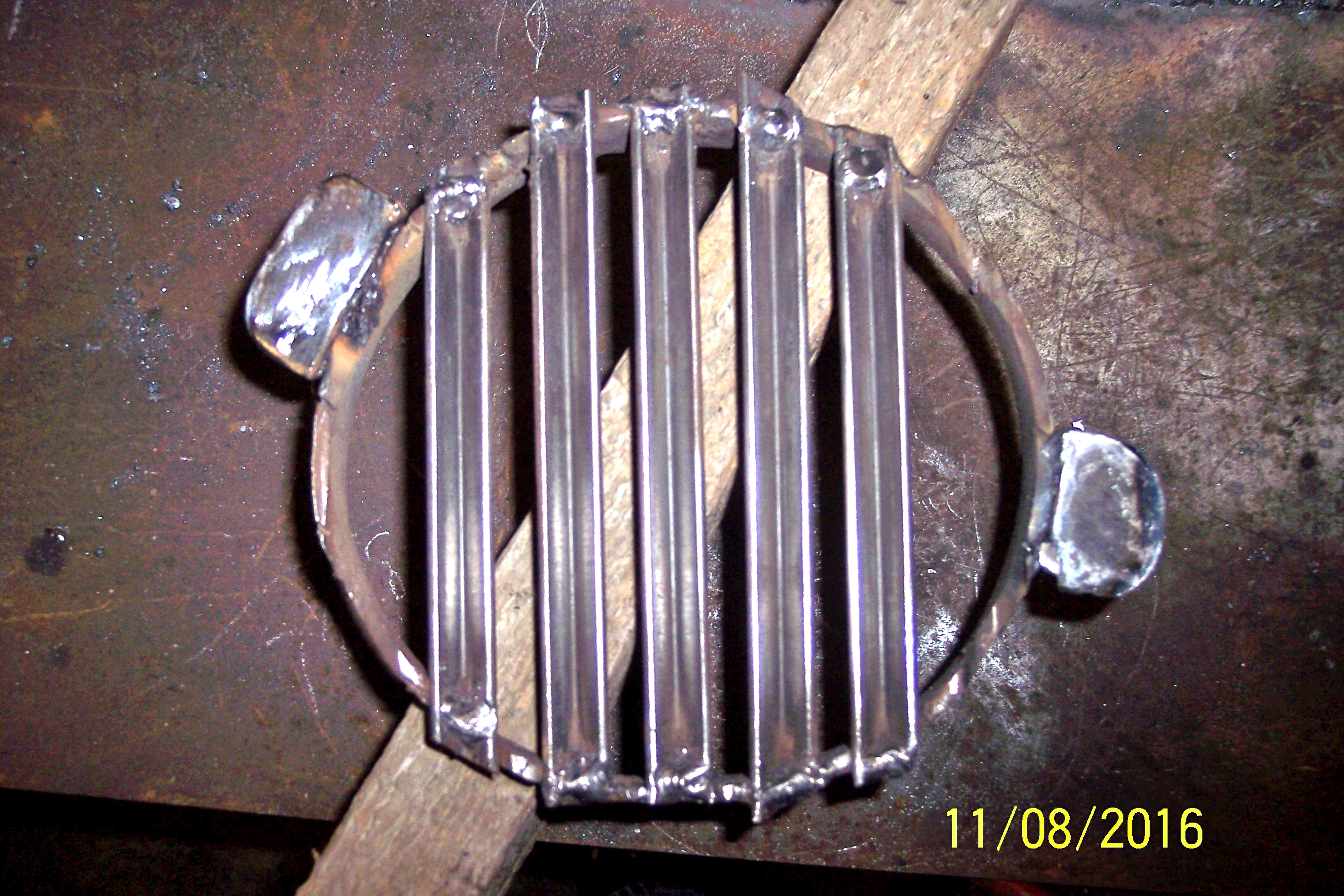
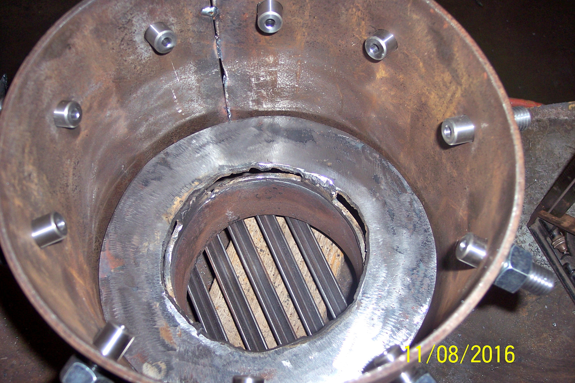
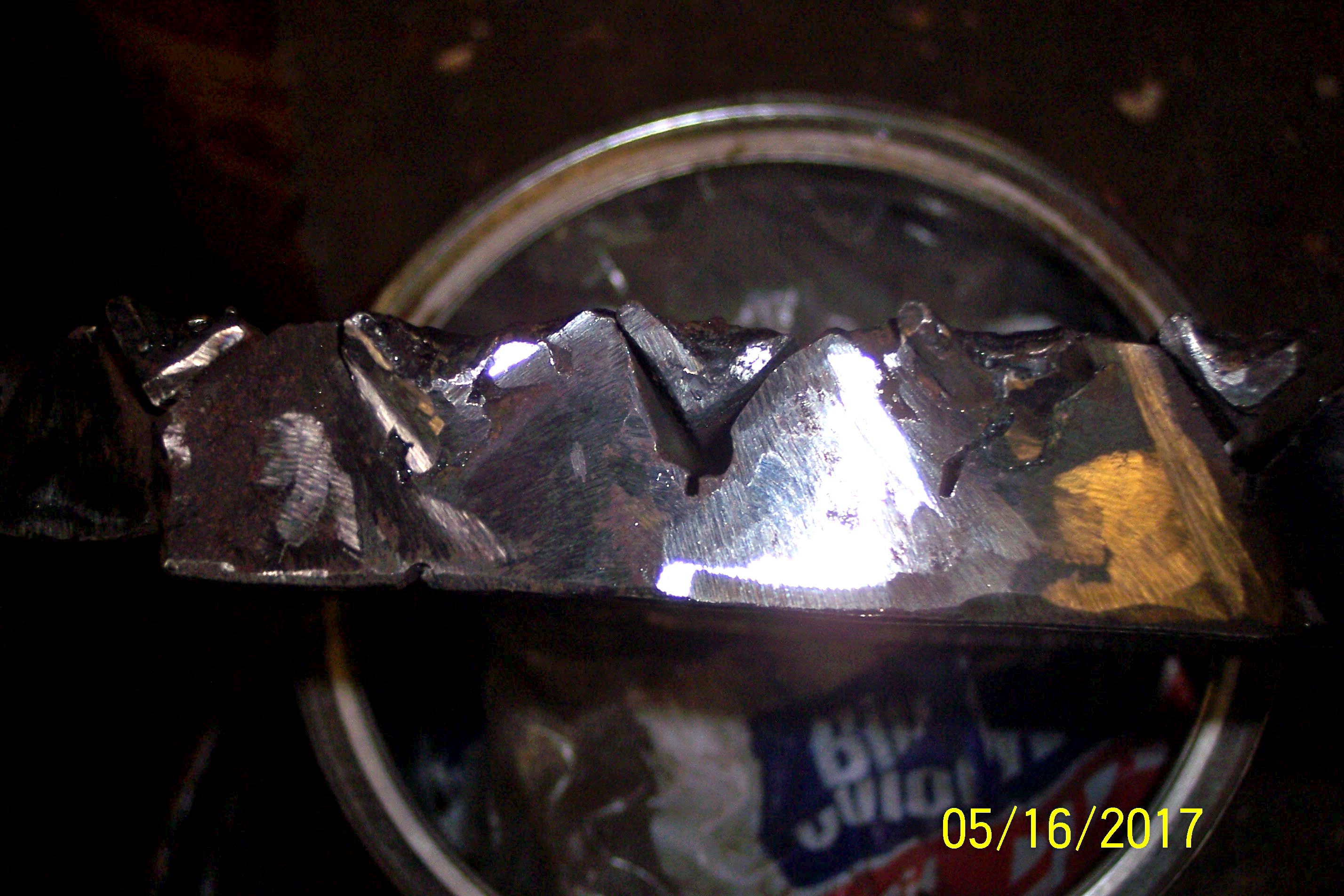
The first two are obvious, other than I made them out of iron and not SS. The third pictures is a little important detail. It is an end view of the angle iron grates attached to a ring. First thing is that I put a weld across the end of each angle to hold the ash in and not allow it to run out the end. The other thing to notice is that the center angle is NOT welded onto the ring on this end of the grate bar. The ones on each side of the center ARE welded onto the ring on the viewing end. The grate bars are only welded to the ring on one end to allow for expansion and the welded end alternates with every other grate. TomC
7 Likes
Discussion Possible Gasifier Grates
Post 13
Heat usually, with glowing char and gas hits a grate from above.
Below the grate there usually is a bit cooler space and less radiation?
A grate radiates the received heat further downwards, and “tries” to “survive”.
If we have a fully exposed flat grate-bar surface upward against full glowing char, the heat “intake” is tremendous.
A poor grate-bar has difficulties to “get rid of” the overwhelming “heat-offering” from abowe by radiating it downward.
Now, if the upper and lower surfaces are about the same
the grate bar will “settle” for a mean temperature between the intensively glowing char and the ash temperature below.
Practice is teaching, that this temperature is too high for any long endurance for low grade materials.
…
I was saying, that adjusting the ratio between heat intake and delivery outward
from a grate bar will affect its mean temperature and lifetime!
…
When the upper face of of a grate-bar is mostly covered by ash, the heat-receiving ability is grately reduced.
This will “tilt” the ratio in/out favorably.
Using an angle-iron profile as grate bar will increase the outward (downward) radiating surface by 1.4 times compared to a flat surface.
The upward facing “ditch” will keep a steady layer of hardening ash for its protection against radiation.
3 Likes
I wanted to do something else look at this part
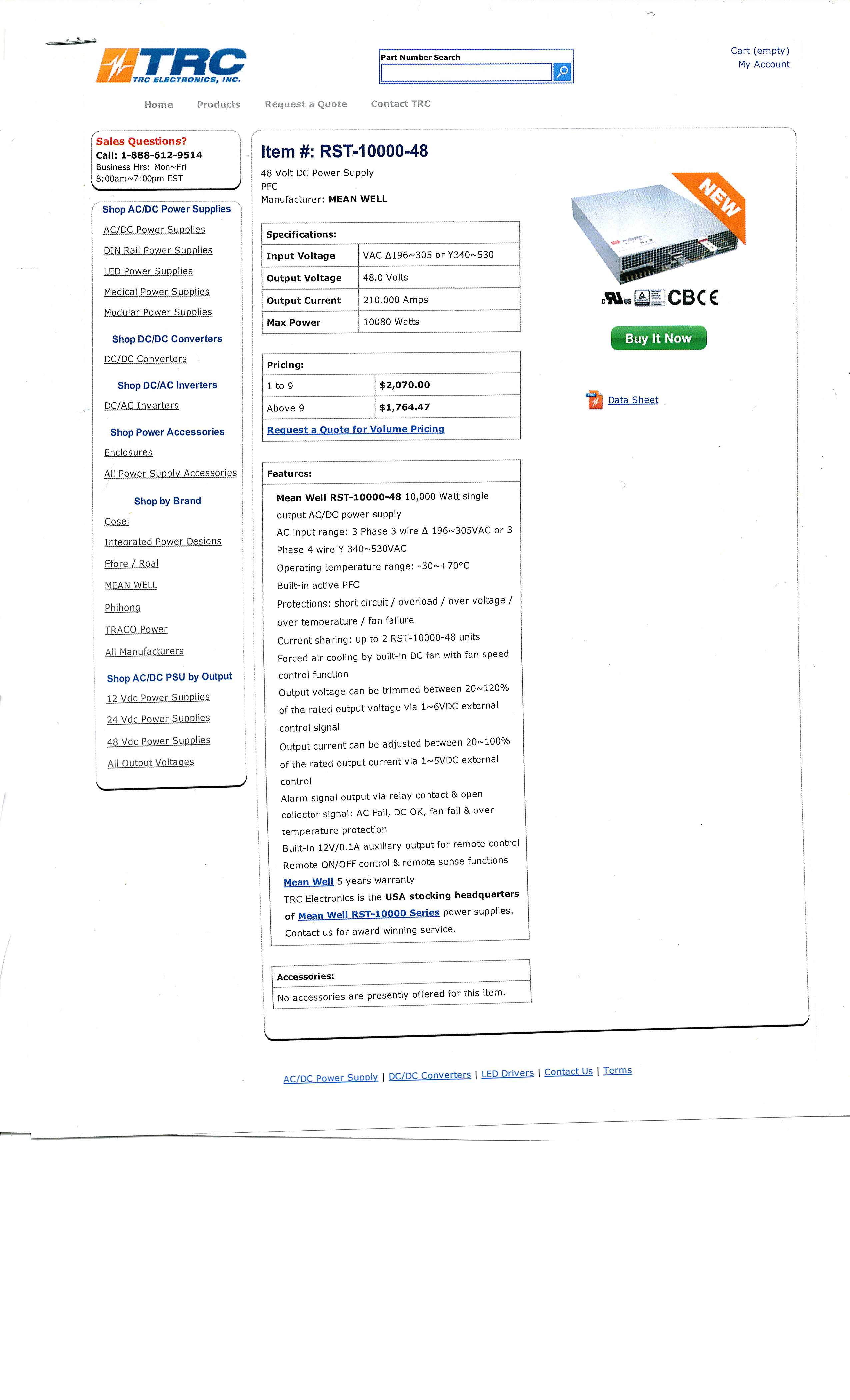
I had to use battery bank or inverter would not have been approved by utility .
I would have liked to use , generator ,
power supply , capacitor bank , and inverter
I am not sure there is a smaller power supply
I think it would explode a battery bank
2 Likes
This is a larger plant
I own stock in the company
Boden, Sweden.
B&W Vølund’s customer, Bodens Energi AB (BEAB), is a municipally owned producer and distributor of electricity and heating. The boiler, featuring a DynaGrate® combustion grate system and with a thermal capacity of 35 megawatts, will be added to BEAB’s existing plant and will supply steam for power generation and district heating. B&W Vølund completed the existing Boden facility in 2008.
2 Likes
Tom after looking at your gasifier I worry I dont get enough air inside with my fiwe nossles, what engine is the gasifier on the pictures made for?
Roger; My engine is a 4.3 L but that is not important to you. The number of nozzles is not necessarily important. The important thing is the amount of air that flows into the oxidation area, which is a balance of number of nozzles and the diameter of the orifice in each nozzle. Otherwise the total area of the orifices. To figure this you have to start with the “volume of air pumped by the engine at a given RPM”. People have written books on this so rather than me trying to write a book, I will try to direct you to some that I have found helpful. (they are in DOW library )
FAO 72---- Appendix 2, pg 130 for an overview. Then back to Chapter 2 & 3 for details.
Handbook of Biomass Downdraft Gasifiers for Engine Systems---- Table 5.2 pg.37. Also have noted pg35 for superficial Velocity/ Hearth Load
Swedish Academy of Engineering-- Experiments from 1939-45 — In particular pg 118 - 129
Unfortunately I could not find the table that I really wanted for you. I’m afraid you will have to do a lot of reading and follow the calculation they show and substitute your dimensions into the equations. I find the Embert style gasifier is critical to the dimensions. You don’t just say, “oh that looks about right”.
I will look for the other table and if I find it I will let you know. TomC
2 Likes
Max has generously provided us a lot of simple equations for more or less anything gasifier related.
First you calculate gas demand at given rpm and wot. The formula is
(Rpm:1000)x(displacement:1000)x3=(pure cool gas need in L/s)
So for you,
1.8x2x3=10.8l/s
Your oxidation zone is supposed to be 5-10% of that, so say 7,5% or 0,8l. This is the triangle rangeing from nozzle tips down to restriction at a 60° slope.
Your restriscion diameter formula.
Squere root(4:pi x 2,5 x l/s) = diameter of restriction
Or 59mm
total nozzle area shuld be about 10% of restriction surface area so 264mm2. Divide by number of nozzles and you get individual nozzle sca, from wich you calculate its diameter.
As sayd above, this calculation is based for a gasifier for different loads. You willnever idle so you culd go a noch bigger.
7 Likes
Wow! Kristijan you certainly simplified that. I spent hours going back through notes for about 2005 and re-reading articles out of the Library. I will save this post. Thanks TomC
2 Likes
Thank you for the exlanation.
How do you come up with the number 264mm2 nozzle area Kristijan?
They may have different calculators in Slovenia 
I get 273 mm2, which is close though. (10% of the 59 mm restriction csa)
With 5 nozzles you end up with 8 mm openings.
I use seven 8 mm nozzles with a 90 mm restriction.
I think you could easily go with your original plan of five 10 mm nozzles and a 100 mm restriction. I think that looks about right 
As Kristijan mentioned, you will never be running at idle.
1 Like