Thank you Jim!
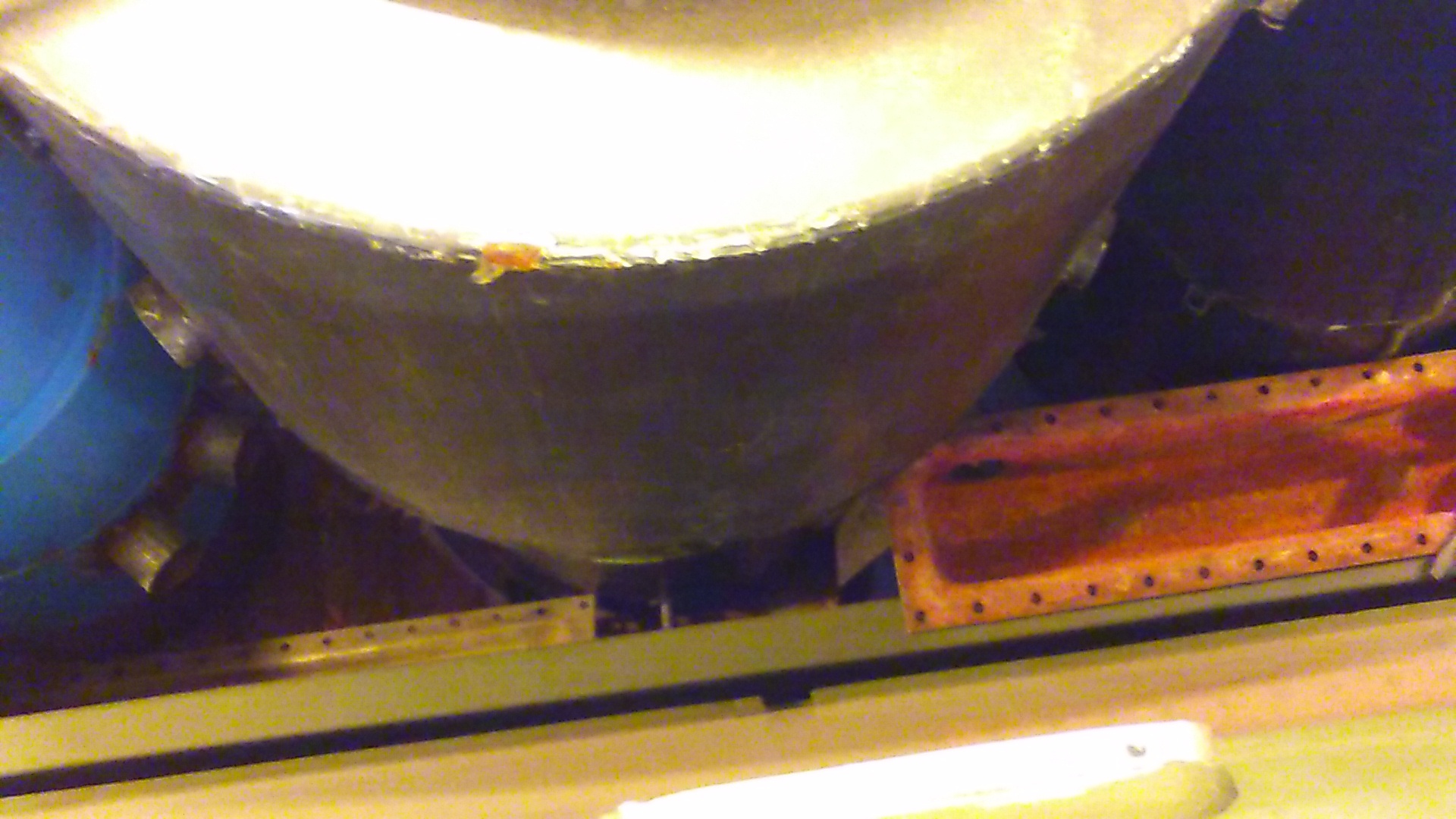
Still, a picture from the back-end of the flatbed, and one from above would give a total image of the arrangement.
It helps to see where a reheater can be placed.
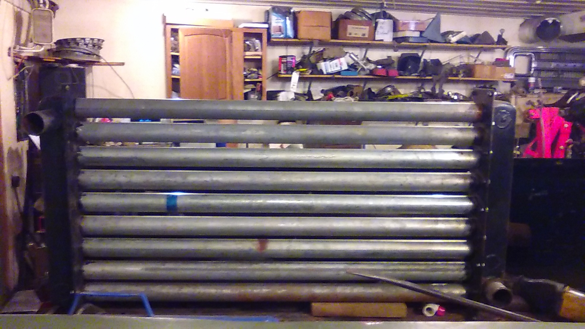
It seems like your current cooler’s “bottom
pan” fits excellent in front of the (hay)filter?
Is it the same one as in the other picture of the “all in one piece” cooler?
Don’t cut the vertical tubes before a practical test is done! The results of the test are valuable!
Test results are manifold better than imaginations!
They “calibrate” the planning forward.
Max
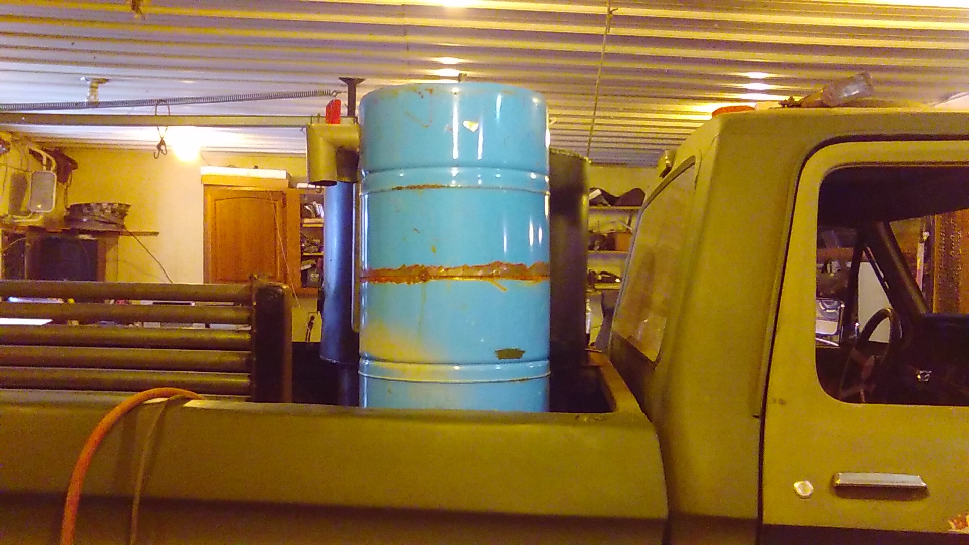
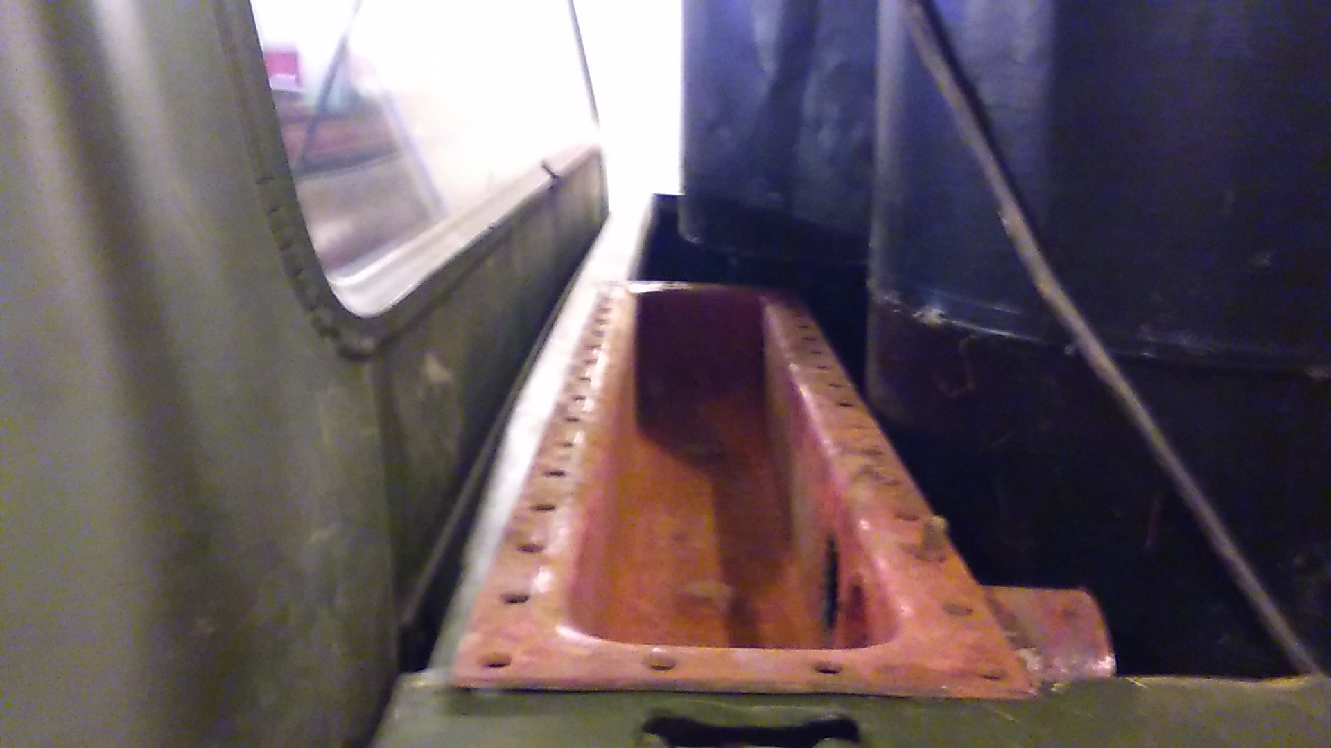
Tthis opening will be the place to get the heat needed. Another heat exchanger, say from gas furnace on a box. Hot gas to condensate tank reheating gas from cooler below hay filter. Blue filter in pic can be replaced and used in next system in a Dakota.
Thanks, Jim!
Until you have installed the right side heatexchanger there is no reason to suggest new items, I think.
Here seems to be items needing some “specification”, before commenting…
Max
Max , until you suggested reheating the gas I had no intentions to have another heat exchanger there at this time. This is my first gasified truck. I have never even driven it on gasoline yet. When I started building this gasifier I was uncertain of its mate so I left options. The lower drum is galvanized an don’t want to have to weld on it again. Even if I do not reheat now I like to plan ahead so future mods can be added in modules. At this time it looks like a good place to add another cooling module with a reheat exchanger module option a planed easy add on. I respect and value your opinion and thoughts on this. Thank You , Jim
Looks like you went with home built barrow, you got a darn good start at it, i bought a quart of BBQ paint from true value hard ware the other day,now i got too get my tubeing lined up for hopper cooler.So i can sand and paint inside the hopper too keep the metal good longer [Looks good].
Hi Jim!
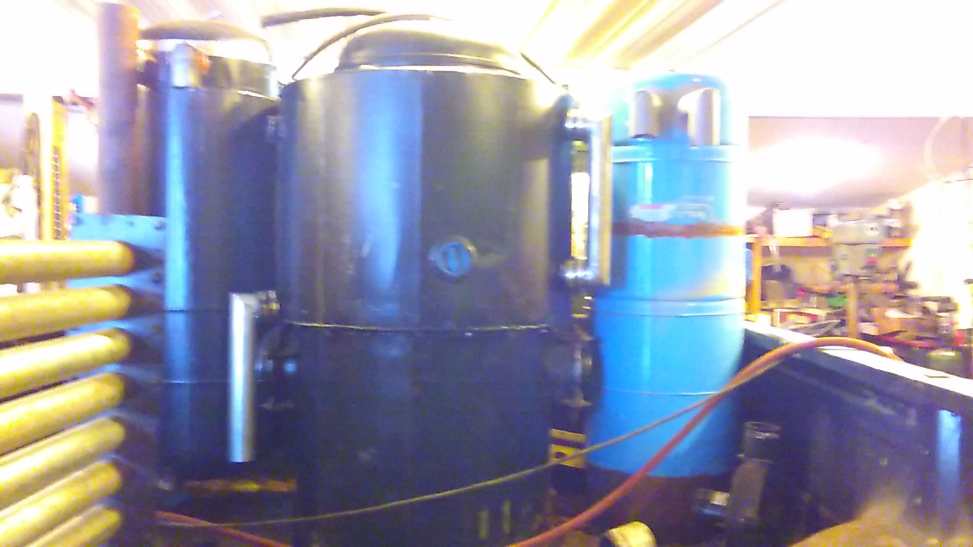
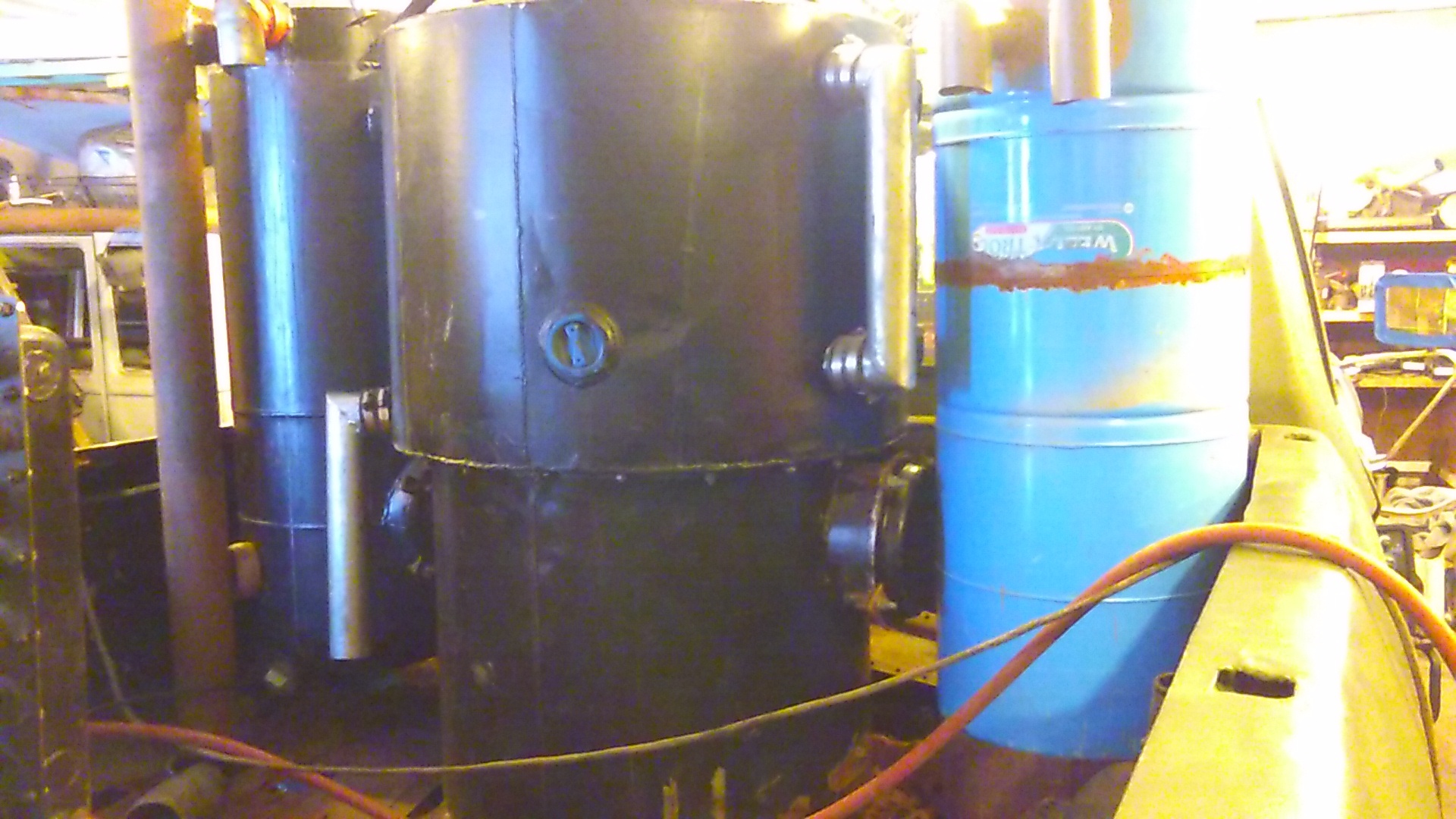
Even to the point when you presented your first picture (the cooler bottom), I thought that your layout was identical with the WK system.
Meaning, that the middle barrel was the heatexchanger, left one (hay)filter, etc…
Now, with the intake-air heatexchanger to the left, is the right hand opening on the gasifier providing both gas out and primary air intake, as on the left side?
Anyway, according to my misconception, I was thinking of welding-on an extra layer on the “heatexchanger in the middle” as the outer skin of a reheat exchanger, “stealing” heat from the underlaying hot gas.
This way no extra component had to be built, taking precious space…
Now to the reality of more pictures: Applying this welding-on flat and part-circular, bent around (seen from above) box on the lefthand real heatexchanger for primary air, removing any insulation first of course, will spare a lot of room.
Furthermore, you do not need to use the righthand outlet on the gasifier; saving the space to the right of the gasifier for a (hay)filter, or whatever is needed.
Max
Sorry for the poor pics Max. It is a slightly modified WK. The reactor is just in the center to make things work better below. The Heat exchanger is left. It is also designed to accept another on the right. This was in case I wanted to use it on another application or set it up as a true duel system as Herbs Caddy . Down the road I thought it may be fun for side by side HX comparisons. As in everything I do I like to have a back up plan. The condensate tank is under the bed floor on the far left and built to be insulated easily The exhaust HX is under the left side of the reactor and hopper condensate bin will sit above bed between HX and reactor. A reheat shell on HX is possible. How does on calculate the size needed? What about water? Does it have to drain to the hay filter in the gas piping. Thank you. Off to the salvage yard for materials today.
Hi, Jim!
The HX to reheat area approximately 15 – 20"sq per liter displacement. Wet shunt tube with flap.
It is always beneficial to have a small manual drain.
Max
“Wet shunt tube with flap” could you please explain this? 15- 20 square inches per liter of displacement. Engine displacement? that seems awful small? I am sure velocity must play an enormous roll in reheating as well as cooling?
Hi, Jim!
Yes, ~2 days back the parallel tube for unheated, damp gas with a regulation flap was described.
If the reheater makes the cool, damp gas unnecessarily hot, it can be modified (cooled) with some cool & wet gas which is parallelling (bypassing) the reheater and then mixed in with the “too hot” gas to achieve the wanted temperature.
The flap has to be well centered on its axis in order to stay neutral against “flowpower”. Otherwise a setting can go out of hand…
Yes, the reheating area is determined by the motor displacement.
In fact, the air preheating around the firetube and in the heatexchanger
will “take back” about half of the heat energy leaving the grate-area.
Because of this, it is a good precausion to increase the reheating area for the wet & cool gas to:
31"2 per liter displacement
31"2 X 4,7 = 145,7"2 or ~150"2
150"2 = 1,041667’2
The reheater mantel around part of the heatexchanger cylinder would be ~1" thick.
This seems to be enough; the increase in temperature needs not to be very big, even if the reheated gas has to take the “burden” of the cold secondary air at the mixer. Otherwise cold and heavily humid secondary air can lead to condensation again.
All this counts at a deep frost startup without gasoline.
And the delivery tube/metal hose from the reheater to the mixer has to be insulated.
Max
I’m sorry Max but you lost me again. We were at 15-20squre inches per liter of displacement. 20 x7.4=148squre inches
Hi, Jim!
I just adjusted the reheating area a bit upward, as you were not satisfied, by all means you were right! Was the rest consumable?
Max
I think Max originally said 15-20 square inches per liter, based on a hotter gas temperature, needing less preheat. As you rightly point out, it’s a bit small… there’s no downside to increasing the surface area.
So, 31 square inches per liter will provide double the heat exchange, and perform a bit better at cold startups.
Another thing for folks reading to keep in mind, European decimals are marked by commas, and American usage is periods. When Max writes 4,7 that means the same as we would write 4.7 and so on.
Hopefully this is also “consumable” ie understandable.
Hi, Jim and Chris!
I am Sorry!
Holy cow! At last my eyes opened; 7.4 liter had become 4.7 liter,
which is a “natural size” in the subconscious mind…
So the conscious numbers are:
31"2 X 7.4 liter = 229.4"2
The calculator batteries are OK!
Max
Yes 7.4 liter Max. I still find it amazing That it takes 12 squre meters to cool the gas and only 1 1/2 square feet to reheat it. Much less temp change on the reheat though. I have got a pretty good idea in my head now on how it will all fit togather. At least 1 more trip to jhe junk yard for a few RV bumpers for manifolds on my drive shaft cooler modules.
Hi, Jim!
25.1.2016
For the same gasflow (motor consumption) the heat transfere is dependent on the
area X temperature differens.
The initial cooling aims at shrinking the volume and condensing out as much as possible of the different steams.
Active area limited only in
sub zero Celsius (freezing) conditions.
Theoretically, and practically you want to start up a motor with a “summer-warm” gasmix, or at least a mix which is not immediately making icecrystals on the sparkplug insulators…
Sub-zero C air contains very little humidity in absolute terms = very dry in relative terms.
But the cooled down gas, which cannot be cooled beyond the freezing point
(without a snowfilter) will have 100% humidity = satisfied = like thick fog = mist.
So, to get the gas’ relative humidity down beyond a renewed condensation (100%) as it mixes with the sub-zero C air, the reheat has to theoretically go
equally high above zero as the cool secondary air is below zero C to “balance” on the “condensation edge”.
To be on the dry (safe) side, one has to reheat the gas at least to the double value above zero C as the ambient air is below zero C.
Measured at the entrance of the mixer.
Figure that,
Max
I have a question, is the reheat needed if the outside temperatures are around freezing and above.