I’ve moved my project discussion from “Life goes on - Summer 2025” so as not to take it over.
To reiterate:
I’m getting older and pushing a wheelbarrow on my hillside property is getting more difficult. I could really use a powered wheelbarrow. I live in Chile and there is not a large selection of equipment available, and what is there is very expensive. So I decided to build something myself.
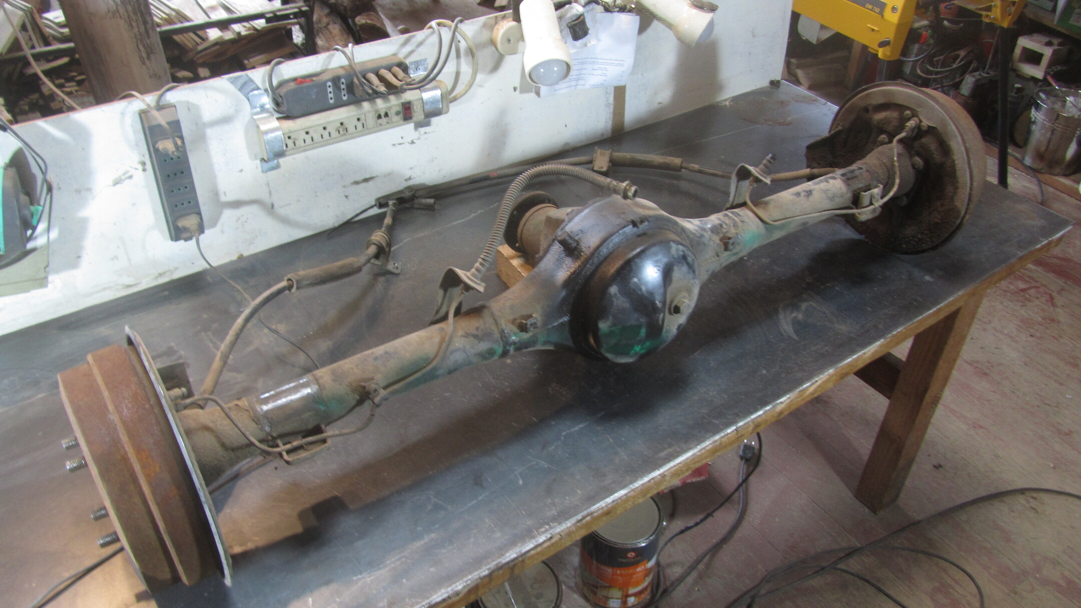
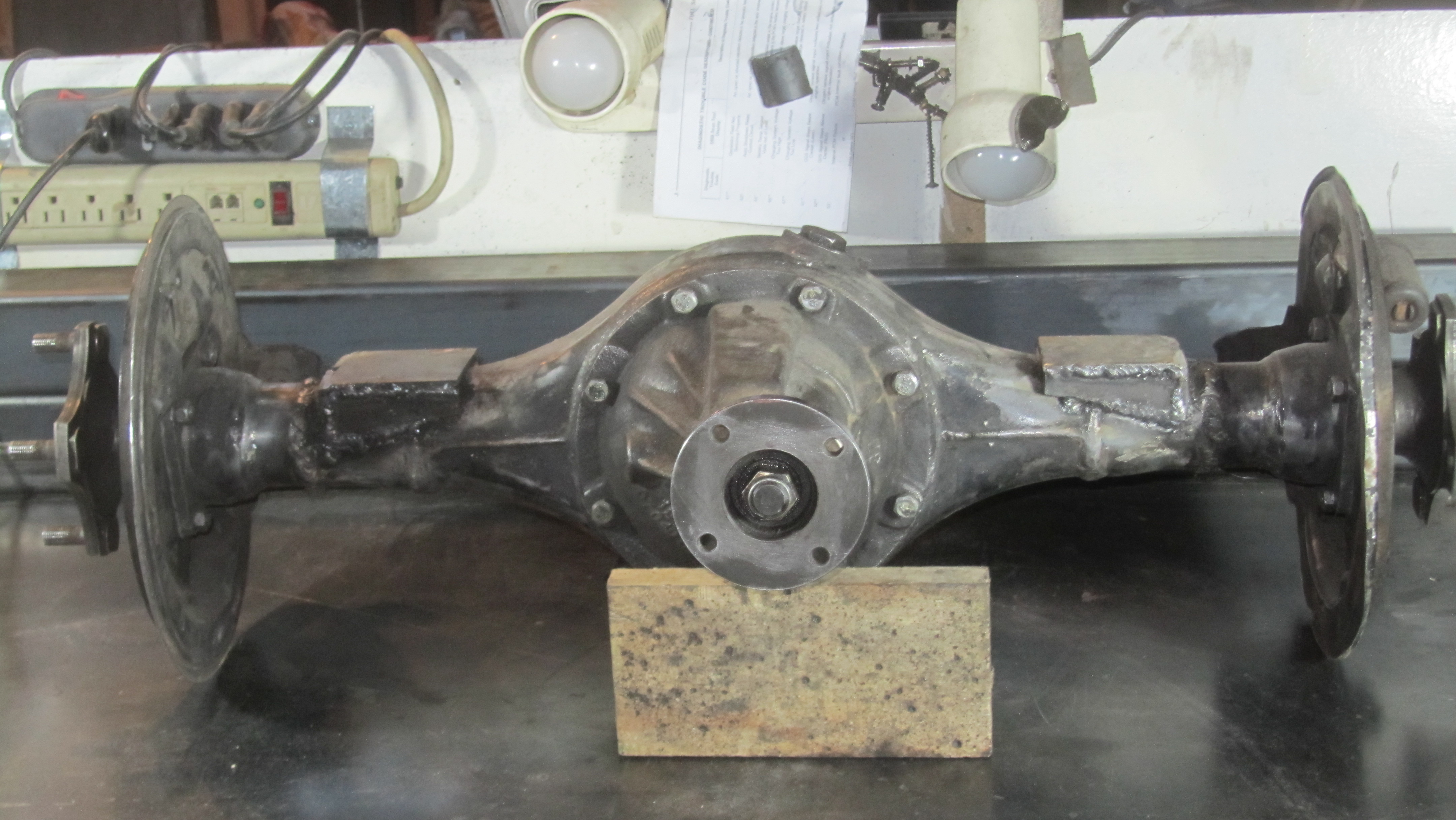
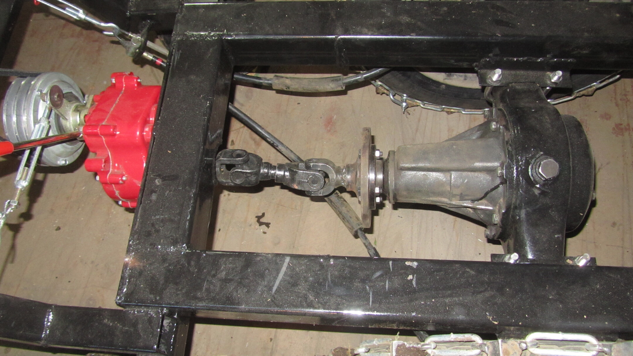
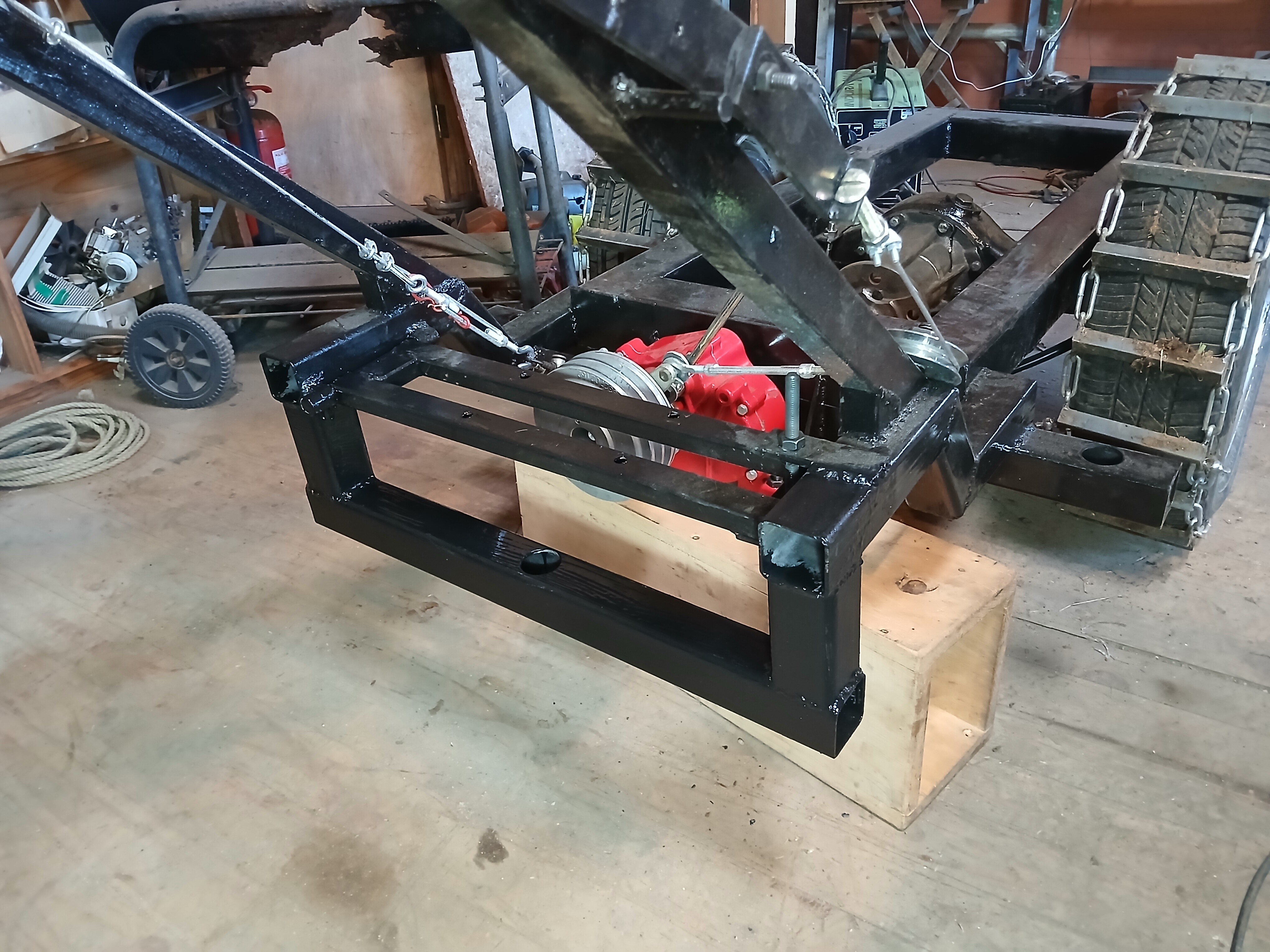
The axle is probably 3 to 4 times heavier than the Powerwagon aluminum axle. It is overkill, but on the other hand, it will be able to take anything I throw at it.
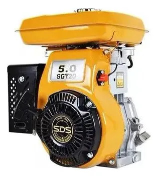
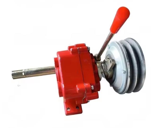
I had considered not using a transmission at all, but I really wanted a reverse gear in case I got in a tight spot with the cart fully loaded. An upside to this decision is that I got 2 forward gears and a dry clutch in addition to the reverse gear.
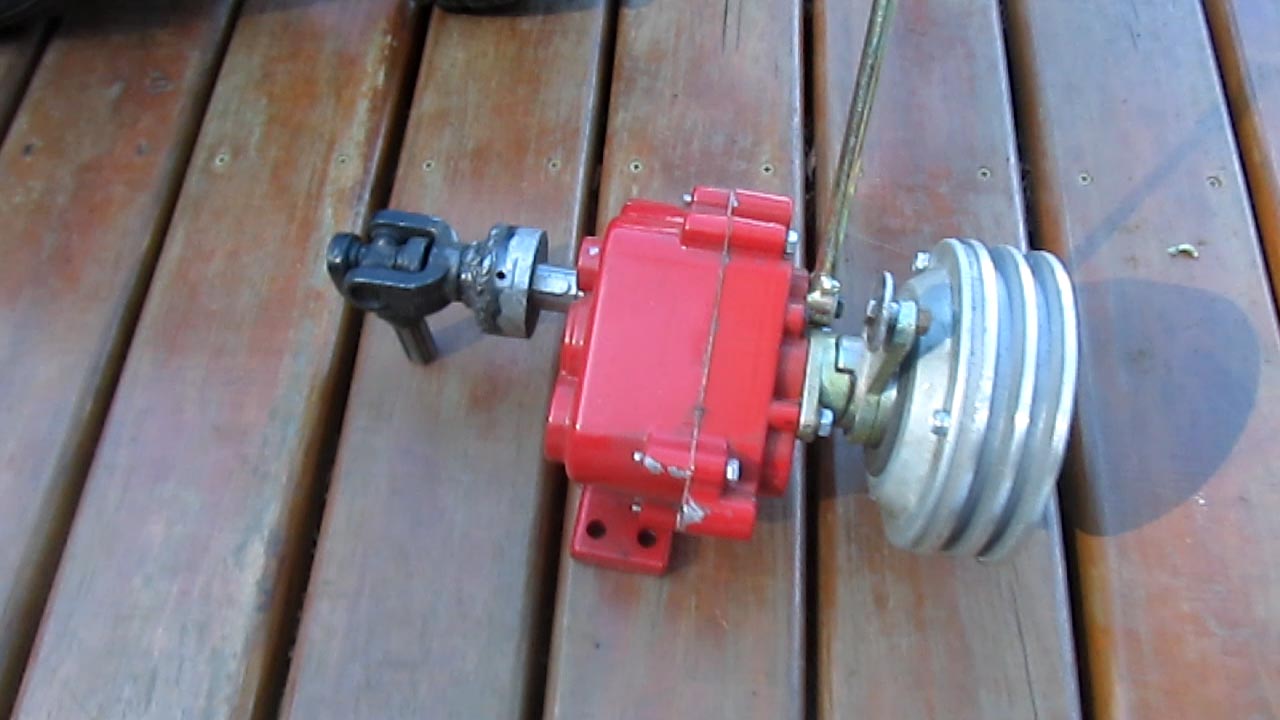
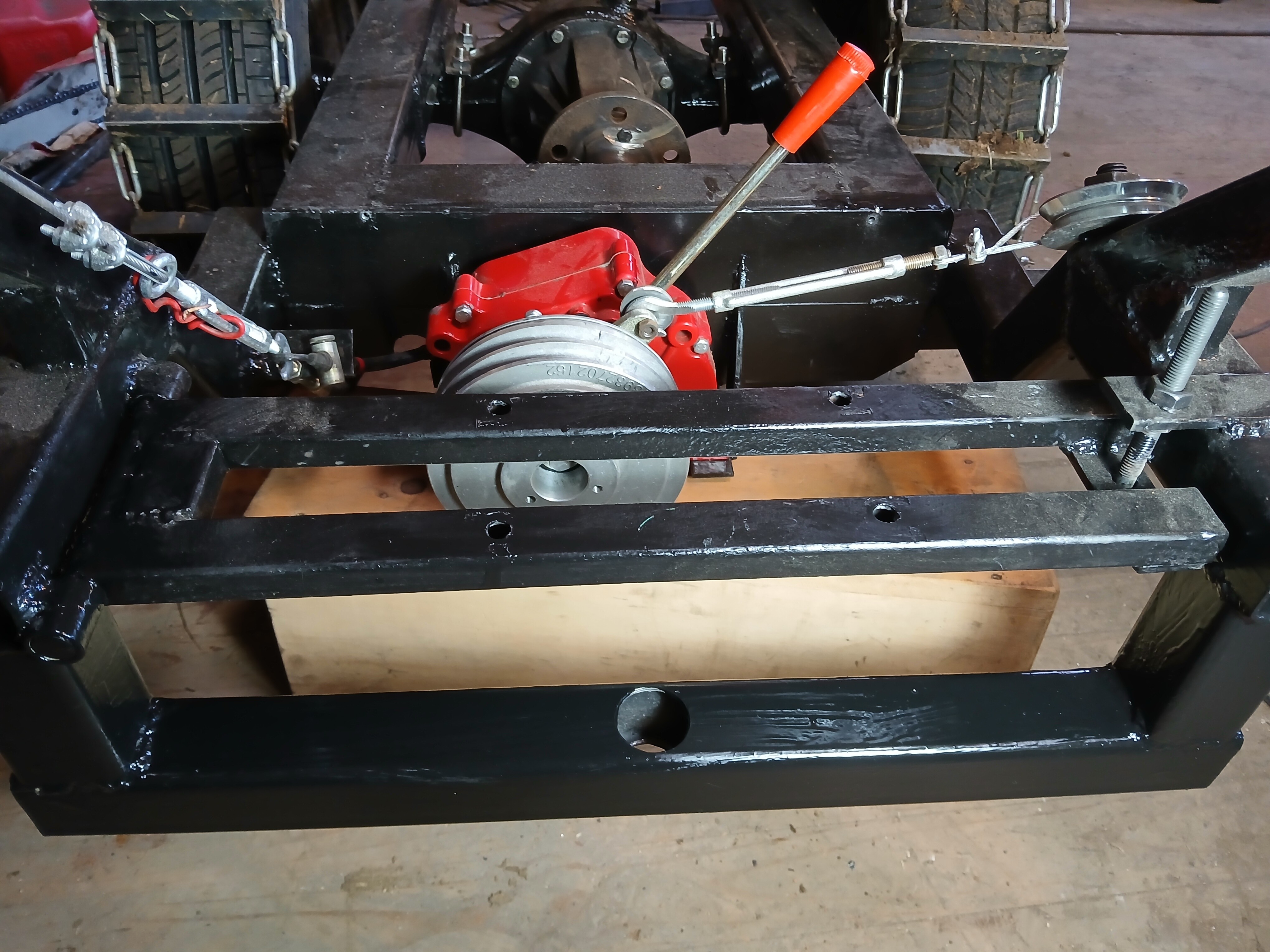
I wanted to use a driveshaft to get power from the tranny to the differential. I had considered a chain drive, but a driveshaft is cleaner and simpler. It was difficult to find suitable U-joints though. The tranny shaft is 25mm in diameter with a splined end. I couldn’t find any joints to fit this, so I cut the spline off and utilized the shorter shaft that had a key slot in it (not shown).
They had six spline male and female connections (smaller diameter than the tranny spline). I welded the female end of one to a chain sprocket (teeth were cut off) that had a keyed 25mm diameter bore that fit perfectly on the tranny shaft. The male shaft of the other joint was welded to a flat plate that was then bolted to the differential flange. Then the two joints were joined by sliding the male end of the tranny joint into the female end of the differential joint.
I do have some reservations regarding the U-joints. I’m sure they would be much happier with a higher rpm / lower torque application. I will have to monitor them and see how they fare over time.
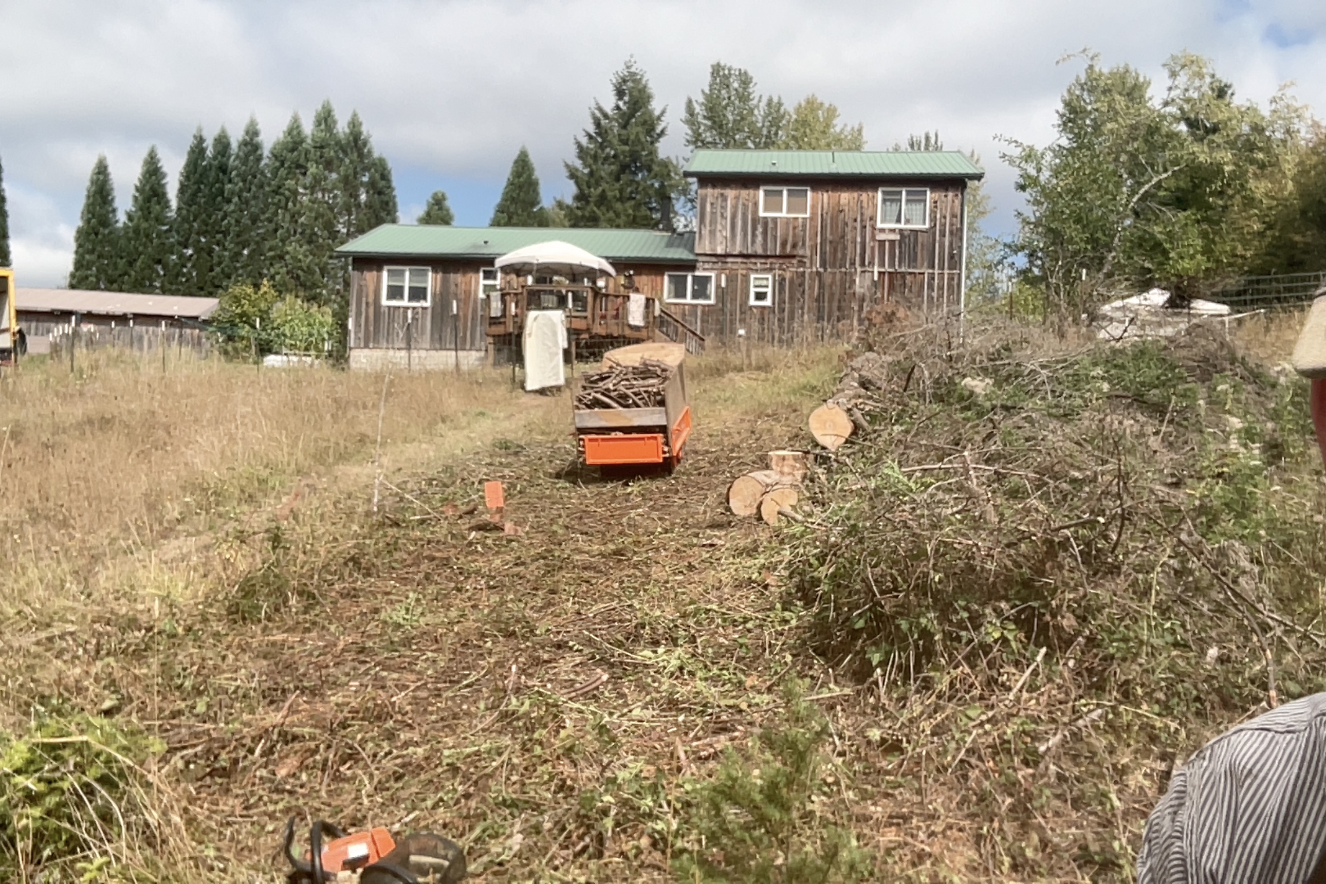
Referring to the video in the first post, you can see I had a little trouble getting up the hill. I had a lot of wheel slip on the uneven ground. I had to lift up, unweighting the caster wheels to get both drive wheels on the ground. I think the design is fine for even, flat ground, but it doesn’t work well on my hill.
So today I tried an experiment. I removed one of the caster wheels and tried the hill again. The cart worked much better even with the offset single caster. The cart is back in the workshop now to change over to a single caster design. I had used the 2 caster design because I needed maximum stability for the hills on my property. But with most of the weight of the loaded cart centered over the axle, I think now the added stability of a second caster is minor.
I will repeat my probably deleted post. I would try to move the caster wheels back so they are behind the weight of the engine ie towards your feet. then the weight of the engine isn’t using the caster as a fulcrum point to lift the drive wheels up when it is unloaded. like drop a piece down from the tube of the engine mount to test it, and you will probably want to brace it if it works.
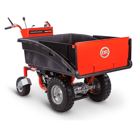
Ideally, you would put the engine under the cart like they have in the DR picture you show which lowers the center of gravity to reduce tipping and it is centered so the cart is pretty balanced on the DR. I don’t think you can do that without a different engine.
Well done Marty , Great build a little fine tuning and you should be ok with it , your terrain looks almost similar to mine even down to the ferns everywhere and the steep land , (well i am on the side of a mountain here )
I couldn’t manage without my Honda tracked motorized wheel barrow over the years the amount of firewood moved is off the scale .
Dave
Yes Sean good idea, I was thinking the same thing.
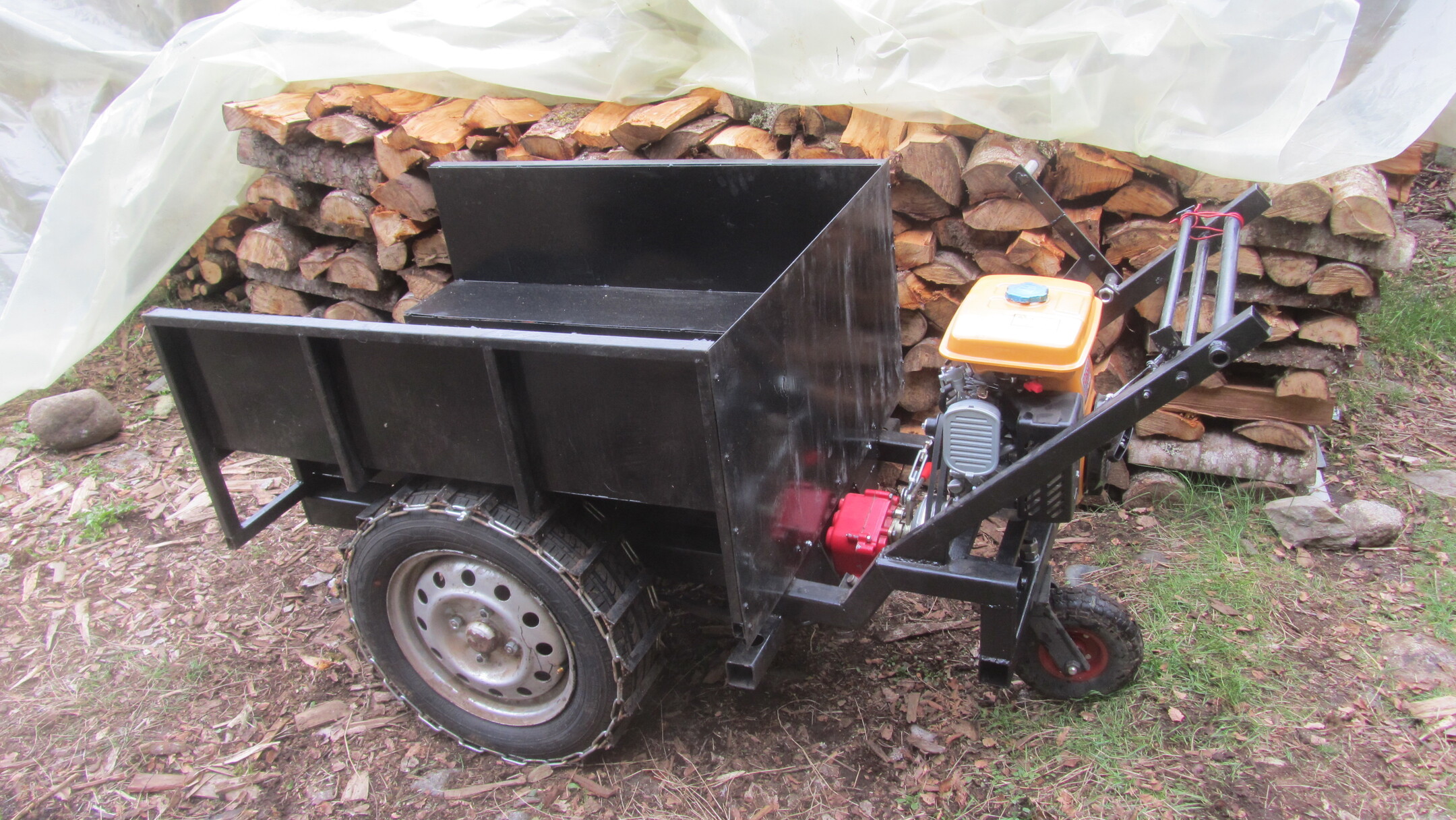
Yeah, I am limited by the engine I have regarding placement. I am also limited by the differential. The DR uses a vertical shaft engine running a belt to their tranny/differential. I had considered rotating my differential 90 degrees to achieve the same effect but the pinion gear housing is too long. Downwards, it would drag on the ground and upwards, it would push the bed up too high and force a higher mount of the engine anyway (and probably starve the bearings in the housing of oil). Since the DR tranny is incorporated into the differential, they can use a light duty belt from the engine. I would have to use a heavy duty chain drive. It just didn’t make much sense to use a vertical shaft engine.
The DR places the bed higher than the tires to get the engine underneath. It makes for a very compact machine, but at the cost of raising the center of gravity. Much of my bed is resting on top of the axle below the top of the tires, so the center of gravity is lowered and offsets the higher mounting of my engine. The engine weight is small relative to the bed weight, so stability is probably not much affected by its higher placement.
Hey MartyS.
I beginning to be envious of your outside wheels placement.
My fits through 32" doorways, narrow space tracks makes for some exciting side-hill traversing experiences:
The section I’ve been traversing along side the fence to the rear of the box van is not fun at all.
Get this tree completely cleaned up and I think I’ll be moving my fence gate over to the right and move the truck along side the R.H. side of the house for straighter up and down sloped travel with the tracked toter.
S.U.
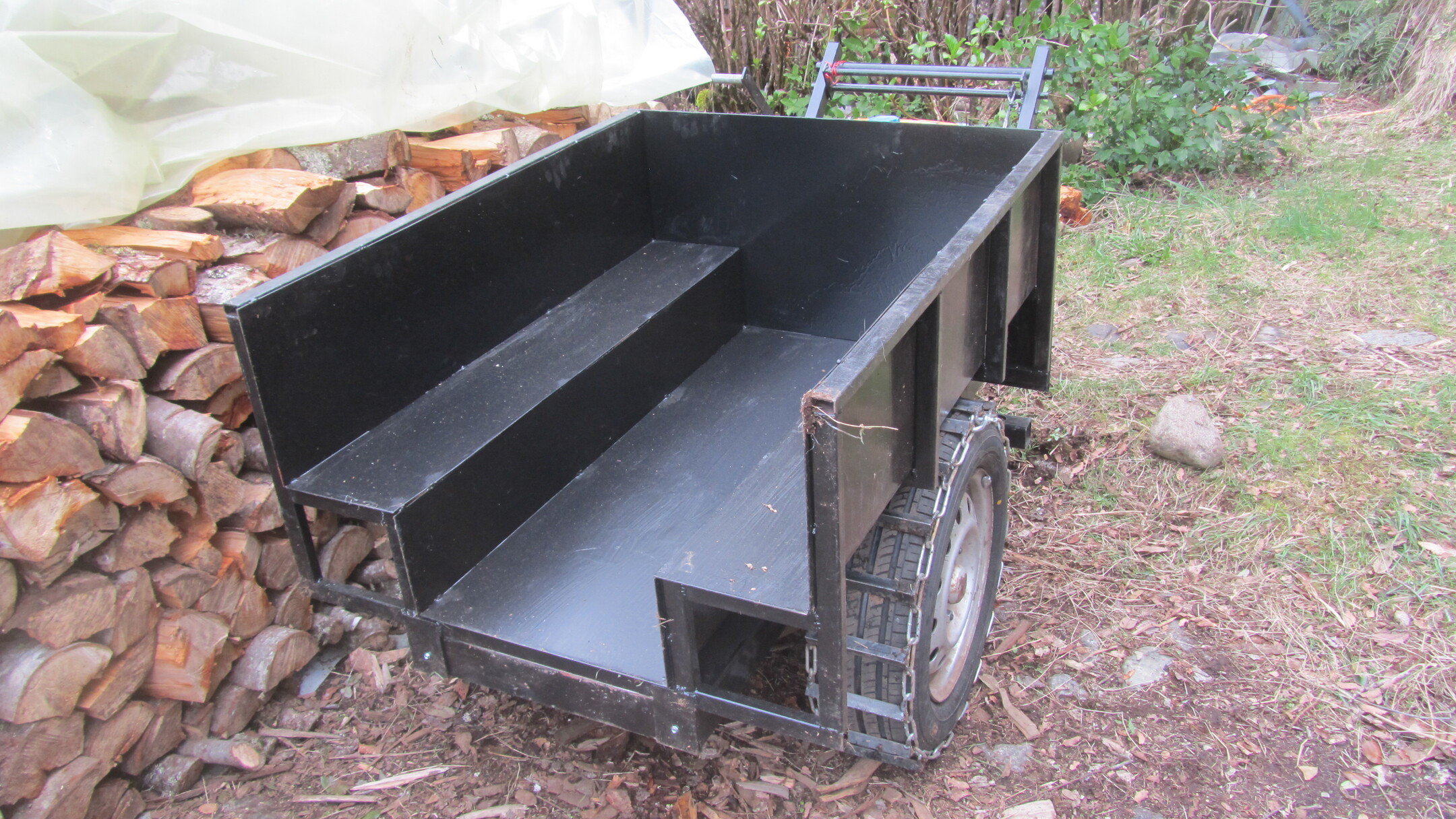
The single caster version performed 100% better than with 2 casters. There was precious little wheel slippage and I didn’t have to struggle like I did with the first version. All that is left is testing with a load.
Before I can do that, I have to do a little path maintenance. Some paths have to be widened a bit and a bridge over a stream has to be rebuilt. Hopefully, I’ll get that done within a few weeks by the time the heating season ends. Then I can use the cart to move already split wood into the woodshed for next year.
Was it worth building the cart? Well, it ended up costing maybe about a third of a new smaller machine. It doesn’t have sophisticated controls, but they work. And the machine is heavy. However, the DR Powerwagon for example, is built lighter but there are complaints about its aluminum transaxle leaking or breaking. I doubt the axle on this machine will ever give me issues. Maybe the U-joints , but not the axle.
I’ll let you all know how it’s going after I start using it for real.
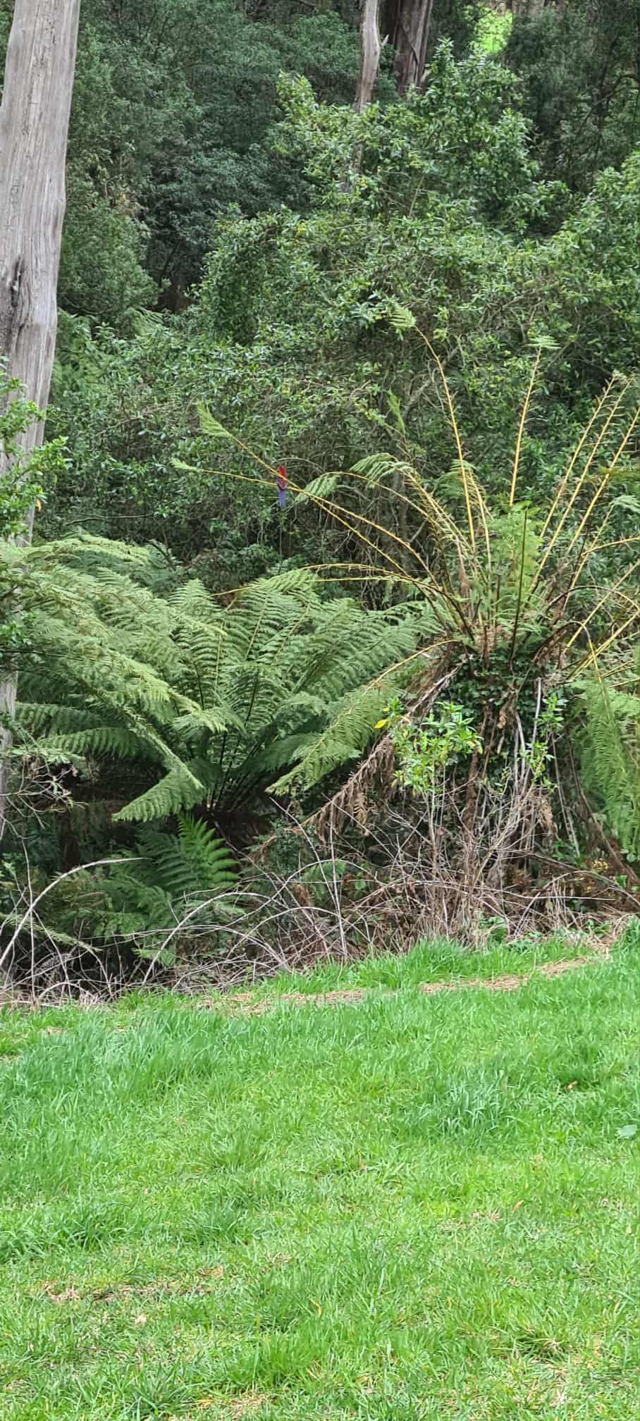
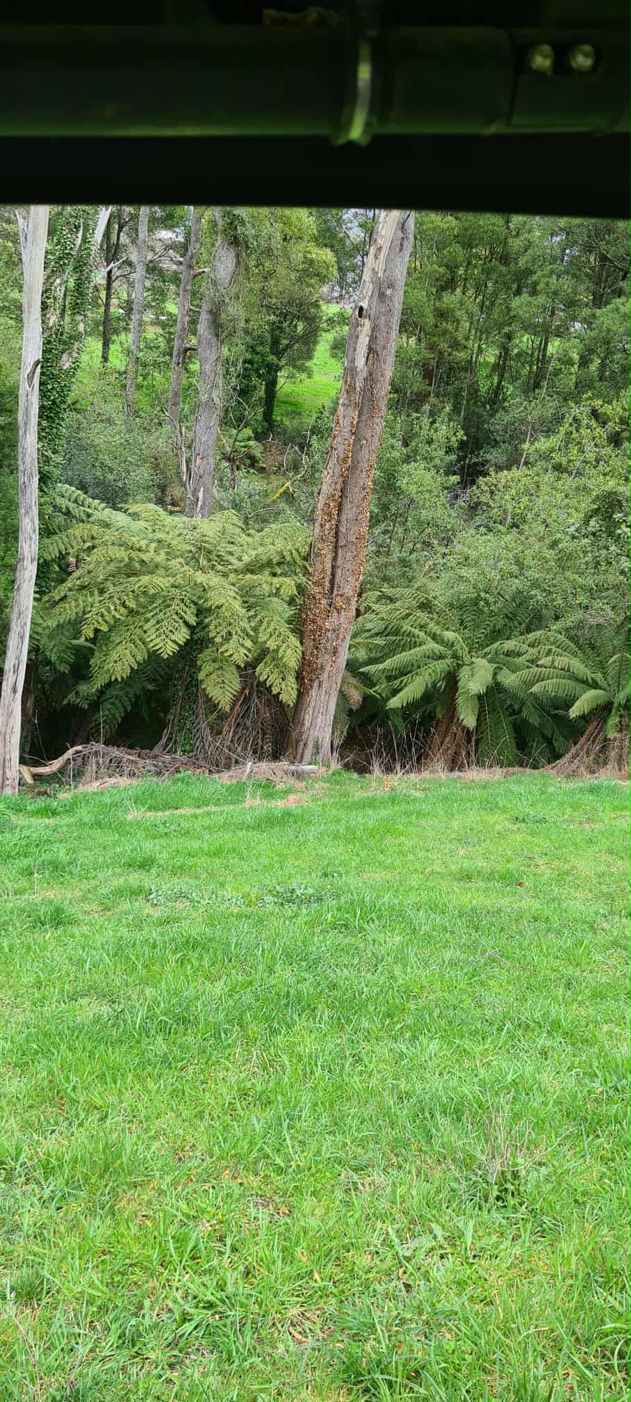
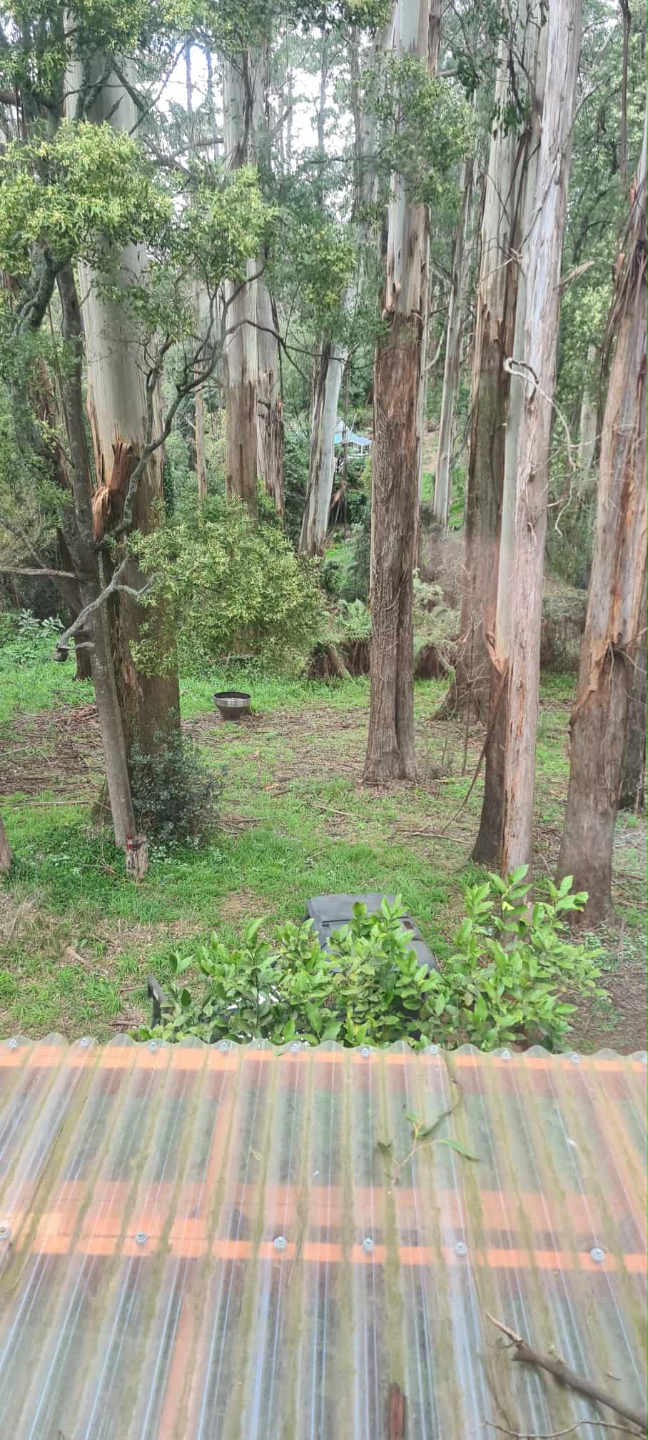
Hi Marty , Here are a couple of photo’s of the Tree ferns at our place there are very large ones around here ,we moved the ones away from the house and down into the bush as the birds keep stripping the Frongs and leaving bare sticks after all the greenery was eaten away , zoom into the first photo and you will just make out a small Parrot having lunch .
Thanks for the picts Dave. Yes, very reminiscent of here. We have some parrots, but not as colorful and very reclusive. Are those eucalyptus trees in the last photo? We got a few of those too!