That would work too, I was just thinking it might be easier to just have it embedded in the cable, have a software switch and be done with it. It also becomes inconspicuous, as you don’t need any extra wires.
What is the frequency of the signal? The nodemcu esp8266 only goes to 1000hz for pwm so it might be a dead end anyway.
Id have to look at the link I posted earlier and this is just something someone else is posting there. So I dont know how credible the info is. But according to that something like 50 hz to 150 hz. After that the ECM starts throwing out trouble codes. But need to verify, in any case it is certainly within the means of Arduino and other controllers.
The pace performance link says:
“The normal range of operating frequency is between 50–150 Hz. The microprocessor inside the sensor is capable of a certain amount of self-diagnosis. An output frequency between 180 Hz and 190 Hz indicates that the fuel is contaminated.” Somewhere in there it is says 5v… they are using resistors to pull the voltage up to 5v which is indicative of a 3.3v output from the board.
It looks like they also sell a wiring harness for 10 bucks that you can hack apart.
The $3 arduino Uno R3 knock-off, like the rest of them ($8 to $30), run at a 16 Mhz clock rate That’s 16 million instructions per second. It’s the time-length of the loop that the user writes which determines the “update rate”. And, using interrupts, one can get an update every 50 microseconds or so.
Example:
The ECU that i am (slowly) designing has to work at up to 6000 rpms (10 msec/rev.). My complete loop may take a couple of milliseconds, but any time an interrupt is triggered, the loop simply stops, the cpu addresses the interrupt request, and the program resumes from where it left off. I can’t think of anything except for getting a crank angle signal that needs updating with every cycle through the main loop. Currently, I am using interrupts to get 4 (90° apart) crank position signals at 6000 rpms and its not a problem. I only do enough math within the interrupt to pass ignition timing info to the loop, so I’m ready for another one in a pretty short period of time.
Pete it all depends on the controller and how fast the hardware is. 2 millisecond is pretty common for plc type conteollers.
In your example straight interrupt logic is a different beast then the plc world I was thinking about. Plc logic is not fast but is guaranteed to always cycle on time.
Things to watch for in the type if interrupt driven process you are looking at.
First how fast does the input capture the intrupt. And how fast does the output circuit actually set the state change. In this respect when you get into these time frames not all controller or micro processor systems are created equal.
Second thing to remember is intrupts are a priority que. So if another intrupt is running or a higher priority intrupt is triggered timing is not guaranteed. This is not a trivial point. I have seen many times where people think they can program an industrial process on a normal pc only to have time critical intrupts not happen on time. If your system is not heavily loaded it will work 9 times out of 10 people test all their code at slow speed and it works great then randomly at process speeds the wheels fall off the bus because some other sensor is providing feedback or the ever fun my machine always crashes at 5 pm every night. Turns out at 5 pm the second shift supervisor goes to lunch and someone starts playing a game on the computer. I have seen that more times then you would believe.
So the short version know your hardware know your total number of intrupts running and know which ones are highest priority. If you check all those things it should work. The other choice is to pick an industrial controller that has know performance rates the faster you need the more you tend to pay. But the industrial controllers will always cycle in the same time if the code is too long to finish in time they throw error codes during the download.
About the flex fuel sensor:
I think Sean has already mentioned some of this, but here’s the best description I have seen so far on what the darn thing really sends to the “computer”:
Fuel Composition Sensor Description
The fuel composition sensor (FCS), also known as the flex fuel sensor, measures the ethanol to gasoline ratio of the fuel in the fuel line to the injectors. Flexible fuel vehicles can be operated with a blend of ethanol and gasoline, up to 85 percent ethanol. To optimize the ignition timing and the fuel injection amount, the MegaSquirt® requires information about the percentage of ethanol in the fuel.
The fuel sensor uses a microprocessor to measure the ethanol percentage and fuel temperature, which it uses to produce and output signal. The fuel sensor signal is a square-wave voltage signal. The signal varies in both frequency and pulse width:
The frequency of the signal indicates the ethanol percentage. The output frequency is linear with respect to the percentage of ethanol content in the fuel. The PCM provides an internal pull-up to five volts on the signal circuit, and the fuel sensor pulls the 5 volts to ground in pulses. The normal range of operating frequency is between 50 and 150 Hertz:
50 Hertz indicates 0% ethanol, and
150 Hertz indicates 100% ethanol.
The pulse width indicates the fuel temperature. The normal pulse width is between 1 and 5 milliseconds:
1 millisecond indicates -40°C (-40°F), and
5 milliseconds indicates 125°C (257°F).
That should be plenty of info for folks who want to defeat/modify it using an Arduino, etc…
But it doesn’t look as though one could simply stick a potentiometer in the line to make changes.
Certainly, using interrupts in a practical circuit caused a LOT of mental grief in my house, but once I got over that, not so bad. But, since I do always know what comes next, and that it’ll be one OR the other interrupt, I don’t have the race problems that you discuss. Of course, you must keep the code short enough that the interrupts can not overlap, no matter what, but that isn’t a problem for me.
I think you are missing the fact, that the nodemcu has wireless built in. In this instance speed isn’t critical. It is also a microcontroller with an RTOS, and has interrupts, but the wireless functionality actually eliminates the need for a real switch and wiring to/from the switch. It eliminates some potential wiring issues. You can do it with an Uno, but for the same price or less, you get wireless.
The issue with ECUs gets down to needing separate clocks. The ones in cars that I have seen are quite a bit faster and more robust then the Arduinos. Freescale sells a dev kit for 200 bucks for a single engine, which is scalable to their higher end (multiple cylinder) products.
(it looks like they had gerber files and the software and docs you can just download. the chip itself is like 5 dollars. someone probably has an ebay version of the board…)
Hi Folks,
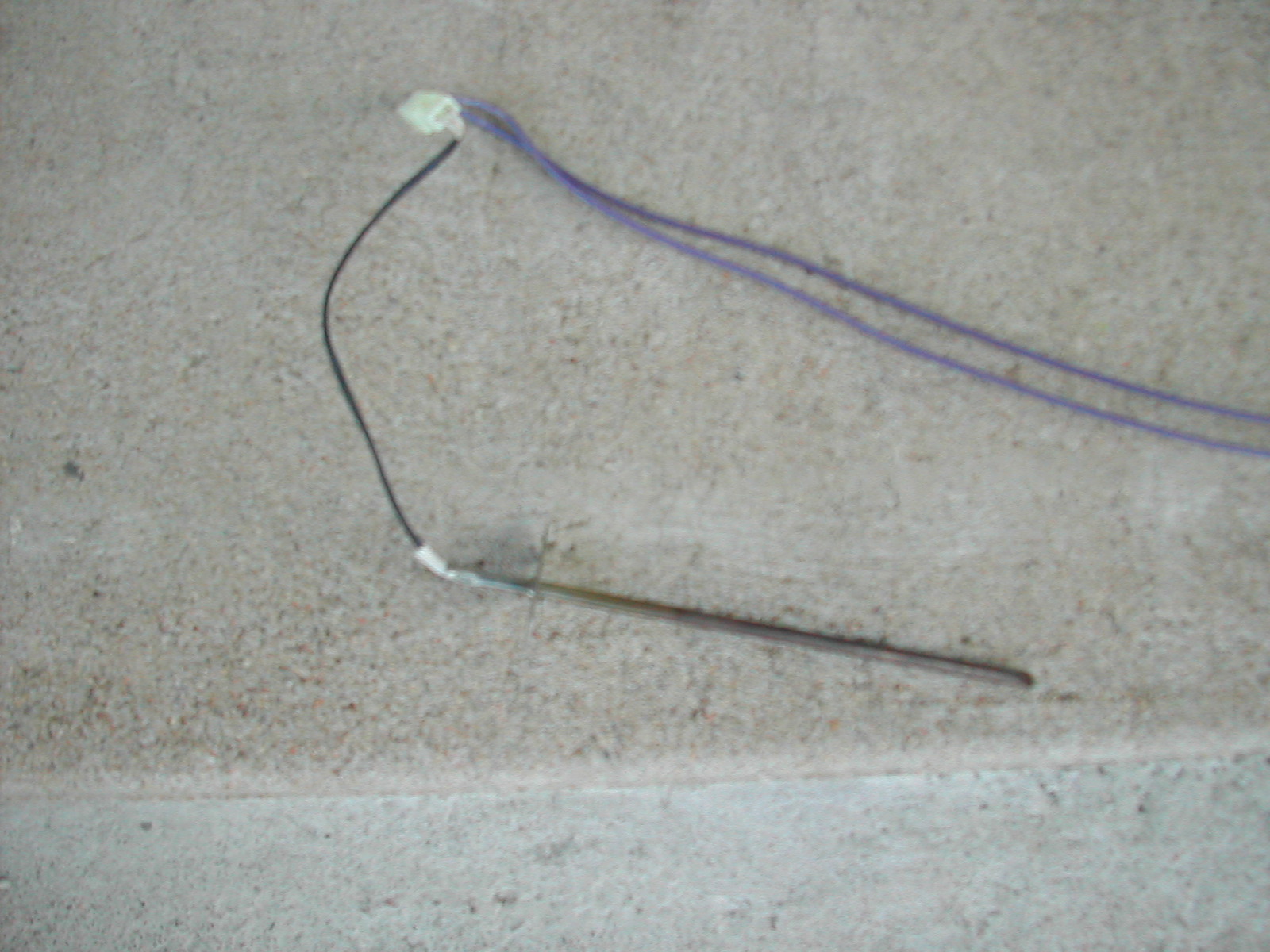
I scrapped an old self cleaning oven, Steve Unruh’s idea. I got some sheet metal, high temp insulation, and possibly a temp sensor from the oven. The resistance changes when I heat it with a propane torch, so I suspect that it is a resistive temperature device (RTD). Please forgive my ignorance if not. It survived red heat from the torch. Does anyone actually know about these things? Could I use it to measure grate temps?
Rindert
Hi Rindert, There are no dumb questions here so feel free. An RTD like that is only good for about 1000 Fmax if it is made really good. Some won’t survive that. They are more in the 100-500 range. And some require 3 wires. Look here : Resistance thermometer - Wikipedia
We mostly use type K thermocouples and readouts made for them. Even a cheap one will go to 1500F.
If the details of the TC don’t say, it is most likely grounded (easier to build) I will search for some ungrounded cheap TCs, but cheap, good, and ungrounded are hard to find.
Thank you for reposting this video about temperature reading systems. I have ALWAYS had trouble with thermo couple readings. I “think” I have followed your instructions by I really can’t say so I guess I should start a ground zero with mine.
I have one that looks like the yellow thermocouple reader you show in your demonstration. I love it, but for driving down the road, it has a timer and after a couple of minutes it turns off automatically. I get it all set up-- power “on”; channel “1 or 2”; temperature reading " C or f"-- every thing good. A couple miles down the road I look down and it has timed out. Can this be simplified-- I love it because I have had the least problem with it and it is accurate (and has its own battery). TomC