I think you just multiply the cc by half the rpms then subtract what ever percentage the AFR is.
3 Likes
What Matt said for the gas+air flow into the engine manifold. If you want to know just the gas in the pipe leading up to the “mixer box” you multiply by the percentage of the gas going into the manifold, or multiply by the percentage of air for the rate of air. TomC
4 Likes
I may be getting in over my head here, but----
A “swept volume” calculation in it’s most simple terms, is the volume of total gases that the engine sucks in, right?
That’s volume = pi X r^2 of the cylinder X piston travel.
-Count the number of intake strokes per unit time Let’s say one minute. (example: for a 4 cycle engine, that’s half the rpms).
Multiply the volume by the number of intake strokes to get total THEORETICAL gases sucked in in one minute.
But that’s where things get hard.
-We don’t know how full the combustion chamber actually gets because of valve timing issues and gas flow restrictions in the intake system.
-If we are talking about woodgas, we don’t know the exact Fuel to Air ratio at any given moment, although we can approximate it. i have heard it’s roughly 1:1 when things are going right.
-An engine at idle has a severe restriction at the mixer, so the cylinder volume is getting a lot less combustion gas. I suppose some math guys can figure that out.
-Of course the engine at “full power” has the least intake restriction as mentiioned earlier.
Well, one thought that comes to mind:
Get a large plastic bag. Based on about half of the theoretical intake volume done earlier, the bag should be large enough to hold a few minutes of woodgas.
Measure its fully inflated volume.
Flatten it out and then completely fill it with the best woodgas you can make.
Set up a valving system so you can port the bag into the woodgas side of the mixer
Get your engine going and warmed up.
Start a timer and switch to the bag.
Run the system until the bag is empty. Stop the timer.
Calculate the number of cc’s, cubic inches or whaterver per minute and you have your answer.
Of course, you could still “split hairs” over the difference between gas from the bag and gas from the reactor.
-It was just a thought.
Anyway, I did use this 'bag" process several years ago (time to FILL the bag) to figure how much gas I could actually get out of my JXQ-10 gasifier. I wanted to see how close the mfr’s specs were to reality. And then, I wanted to see how much beyond the specs I could take it.
I didn’t invent the idea. But I can’t remember where I found it.
Pete Stanaitis
6 Likes
Hi pete, talking about bags, you could hook a big bag to your exhaust pipe start the engine up and time it at a certain rmp. and find out the volume of air and fuel expansion used. Would this give you a good reading also? Just thinking off the top of my head.
Bob
2 Likes
Thats an interesting idea Bob, but you would probably also need to factor in the temperature of the exhaust, as gasses change volume pretty substantially as they are heated.
3 Likes
Agreed. Also a person would have to account for the combustion products vs the fuel, I think there should be a general expansion of gases resulting from a combustion process.
That said, wood gas should be less expansion than gasoline or solid wood.
There should be tables somewhere…
Measuring the exhaust would give a very accurate figure for filling ratios if thermal expansion, and combustion were known. Sounds like a bit of a lab experiment in practice though.
2 Likes
Yikes! I didn’t think it would be so complicated. So many factors. Thanks for all the information.
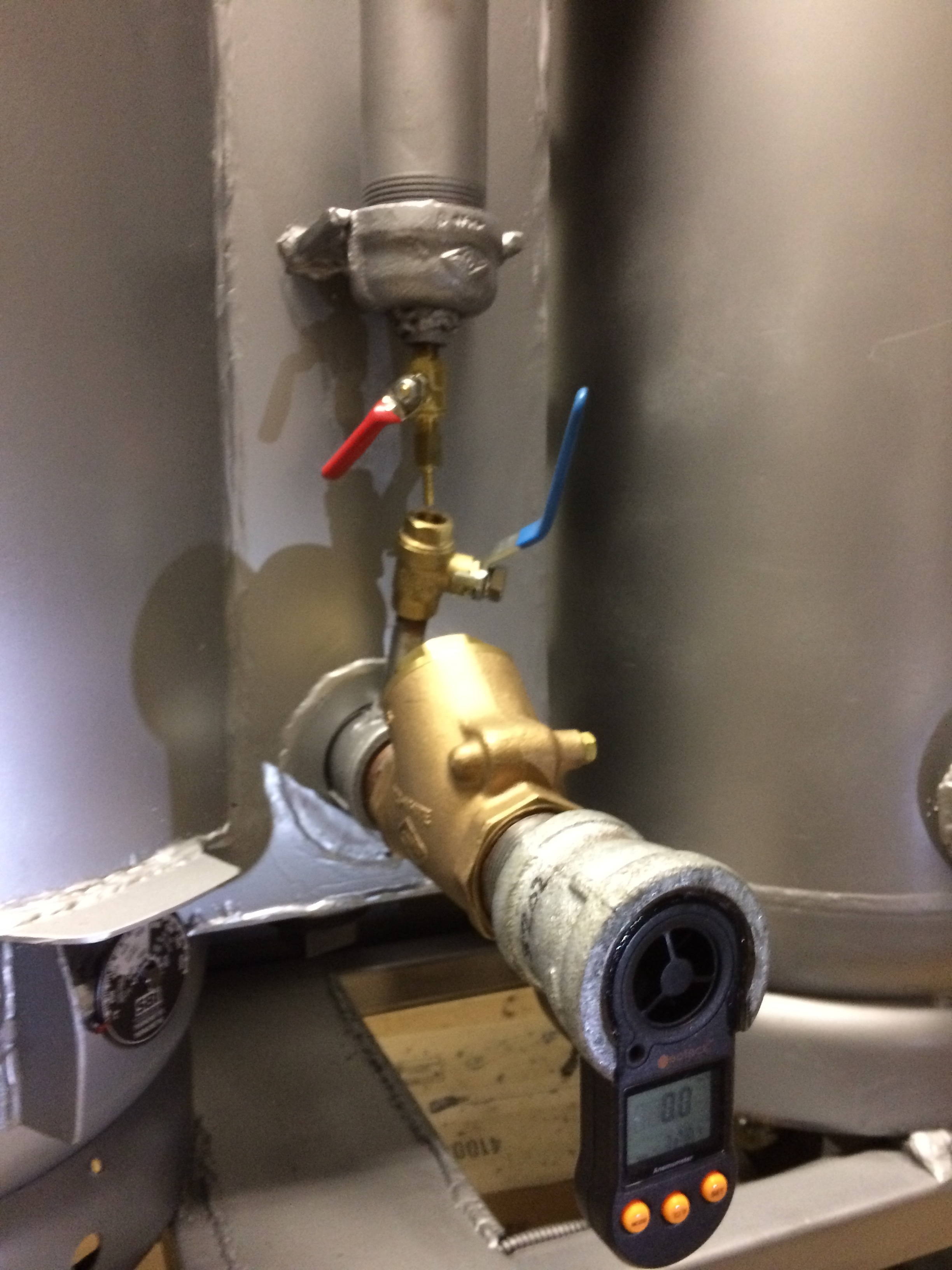
Maybe I should have mentioned that the reason I wanted to know is so I could have realistic air flow rates without the engine, by adjusting the blower to pull air through the gasifier at approximately the same rate as the engine will. In this picture, it shows how I mounted an anemometer over the air intake, in an attempt to measure the rate of flow through the gasifier.
Pete, how do you measure the volume of the fully inflated plastic bag - Do you fill it with water and then measure the water?
7 Likes
Greg:
Depends a bit on the shape of the bag when fully inflated.
If it gets to be pretty close to spherical at the pressure that you can expect, you simply measure the diameter, divide by 2 to get radius, then:
V= 4/3 π r*3
If not, I simply break the shape into a couple of measurable volumes and measure/estimate them. If I am off by 10% or so, I think I am “close enough for gov’t work”, as they say. It all depends on how much you enjoy playing with geometry, I guess.
Pete Stanaitis
4 Likes
You are getting this more complicated than it needs to be. Do just what Matt said, end of story. The only thing that needs explanation is " multiply the cc by half the rpms". In a 4 stroke engine you only pull air/gas in and out on one revolution of every two revolution-- exhaust and intake on one rev. --the other revolution has compression of gases and explosion or power. Thus every two revolutions only one is concerned with air in and out.
208cc/rev x 600 rev/min ( idle) X 1/2 = 62400 cc/min.
I leave the WOT to you as I have no idea what rpm it will run. TomC
9 Likes
OK, so you dont really need to get a number per se - you are just trying to match your blower to your engine draw - right? How about putting a manometer on the outlet of the reactor- a simple U-shaped loop of clear hose with dyed liquid inside works. Instead of measuring and comparing the flow, just measure and compare the suction. I played around with one trying to dial in the right size for a nozzle - they are pretty simple to set up.
I like the anemometer idea, by the way - does it work?
5 Likes
Hey GregC,
Matching any single or dual cylinder engine gasses-in volume flows to a gasifier blower rate does not work very well at all in real-use practice.
The blower flow is constant.
Each engine cylinder on a four stoke is suck (for 15-25% of the time) then no-suck: wait; wait, wait.
Once you get to 3 or more cylinders only then do you get enough individual sucking events overlapping to have a usable steady enough intake vacuum and flow rate characteristics.
Single and two/twin cylinders four stokes do gasifer work obviously.
On these best to use the intake sucking pulsations feeding back for advantages . . . like . . .
your-use experiences, will teach you this.
Do, use, and learn from the doings.
Too tempting easy to over-think.
S.U.
5 Likes
Also GregC do realize and learn well that a raw wood fueled gasifier is a heats Deficit system.
A charcoal fueled gasifier is a heats Excessive system.
These terms and explanations are in all of the good 1870’s thru 2000’s published gasification books.
Any and all raw wood gasifiers when the raw input wood fuels are used up, ran low, turn themselves into charcoal gasifiers.
The large engine, hard engine pulled wood gasifers then run into system metals damaging real quickly. Read the hard roads driven topic threads here on the DOW to see this.
Your little single cylinder engine on a Ben’s Book system should be ok using strictly just outside made woodchar.
Upsize the engine size/demand and you’d really, really be forced to change to a true charcoal gasifier design due to seams popping, warpages, and wall burn throughs.
True charcoal designs like Ben’s Mustang car system. Gary Gillmore’s now larger vehicle system. Pedrick. And other historic system types…
These are designed for heats Excessive uses. Distance spacing, and non-active char insulating the system metals from the active char-glow radiant heat energy releases.
S.U.
6 Likes
I want to test the gasifier by having it use air (and produce gas) at the same rate as my engine will use the gas.
The anemometer seems to work fine. It measures meters per second and I multiply that by the cross sectional area of the inlet to get the volume of air per second.
3 Likes
I like the manometer-U-loop idea. So simple. I have hooked up an electronic manometer, but that is unnecessarily complicated.
2 Likes
Thanks for the warning, Steve. I have added a dropper to add measured amounts of water, by the drop, to the incoming air. I wonder if that will keep it cool enough?
2 Likes
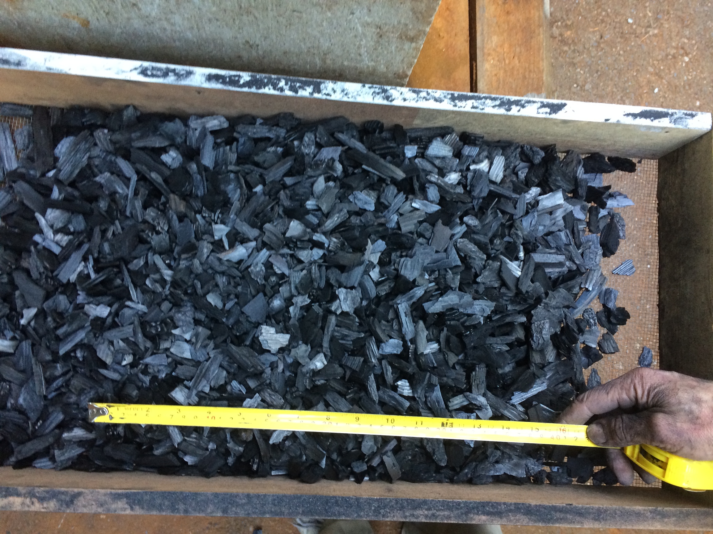
This is my first batch of ‘engine grade charcoal’. Is the size right?
In this video, I show some things I added to the gasifier, to help me understand what is going on inside it. I can measure temperature in the hopper, the hearth, the reduction tube exit, the filter (not shown) and the flame. Pressure can be measured in the hopper and in the filter. Air flow is controlled by the PWM for the over-priced blower and air flow is measured by the anemometer at the air intake. Water is added drop by drop to the intake air to theoretically (as I haven’t actually tried it yet) control the hearth temperature.
Question: What temperature is ideal at the hearth for the charcoal to burn at?

7 Likes
Greg,
Exhaust re-circulation is also a way to cool the oxidation zone. The water drip is a good idea. Your engine-grade charcoal looks very good to me!
2 Likes
Sounds like you have got a nice suite of sensors - and a really clean looking build - going there. I look forward to hearing about your results. The size of your charcoal looks like it might be a bit bigger than what I have used - I try to keep it to what will go through half inch hardware cloth (it is hard to tell from a picture though). Are you running it through a grinder, or crushing it by hand?
As for hearth temp, you want to keep it above 700 C in the reaction zone, to keep the Boudouard reaction going at a favorable rate. Its sort of hard to measure directly, due to the extreme temperatures that can occur right at the nozzle, so i have always just had a thermocouple a bit above the reaction lobe, and used that as a indicator. When running with no water drip or EGR, the ash will fuse into glassy slag - which I feel like I read will only occur at around 1200 C. How high does that thermocouple go?
The water does a good job of cooling the reaction, and will also produce H2, which really improves the performance of the gas in my experience. What was your nozzle design, again? Keep up the good work!
7 Likes
The main thermocouple for the hearth area is advertised to go up to 2373° F or 1300° C.
http://www.thermomart.com/kiln-part-instrument/ceramic-thermocouple
The charcoal went thru a 1" hardware cloth, so maybe I need smaller. I got the dust out with 1/8" hardware cloth. I crushed it with a hammer, but I’ll probably build a grinder for future. I’d like to find some plans for one.
I’ll keep the hearth temp below 900° C for my first run, perhaps tomorrow. I don’t want to melt anything.
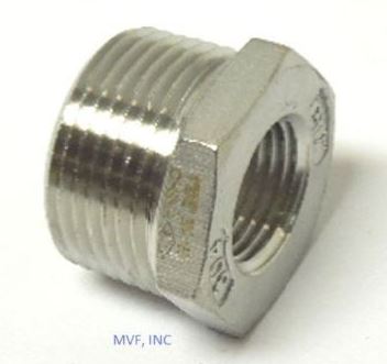
My nozzles were stainless steel npt hex pipe bushings, drilled to 3/8" diameter. They look something like this before drilling.
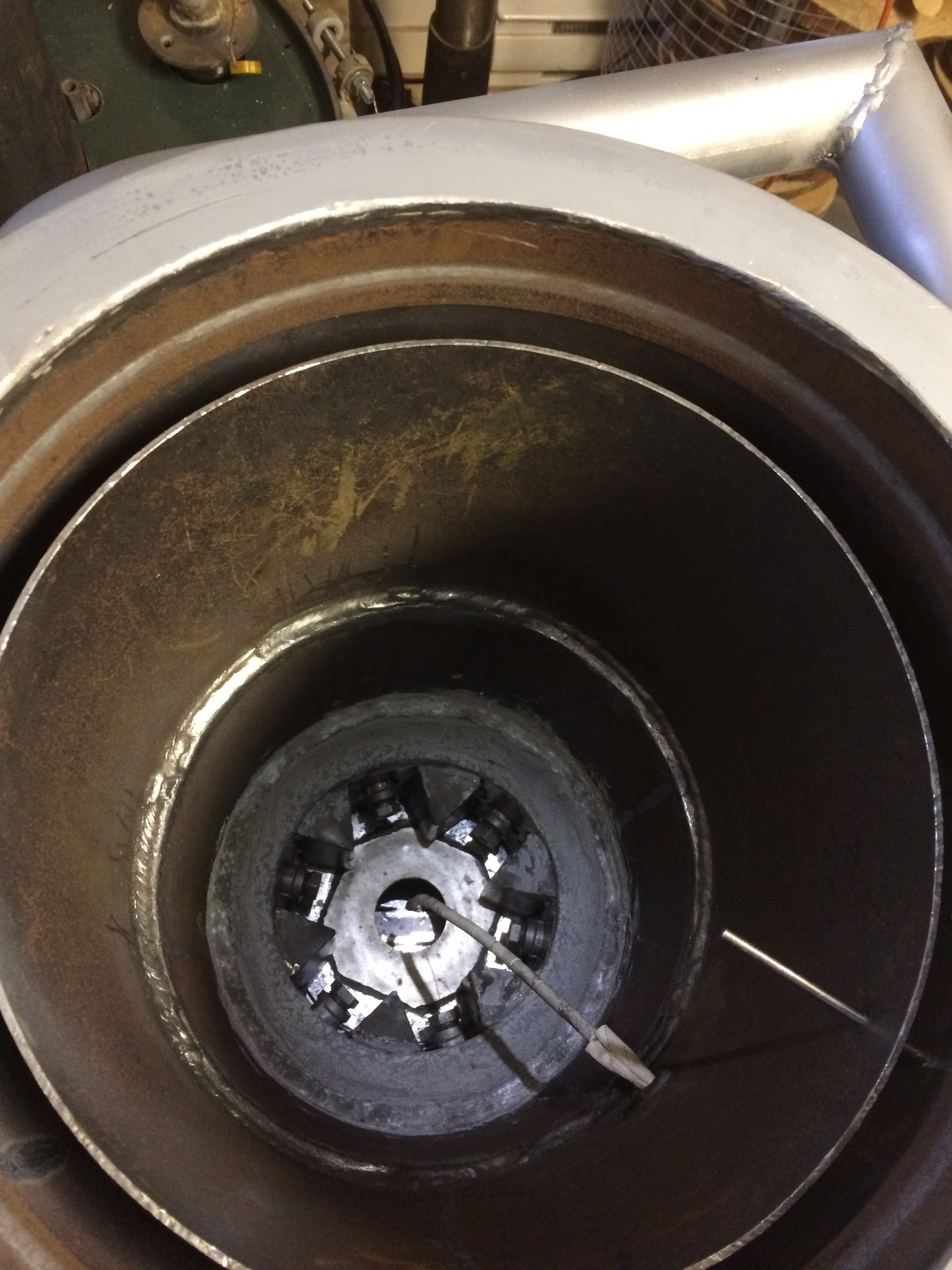
You can see down into the hearth here. There are the 6 nozzles, the choke plate, the grate (in the center), the side of the reduction tube (the black crescent moon shape over the grate) and two of the thermocouples sticking out:
2 Likes
Nice, 1300C should probably be plenty.
This looks cool, I am looking forward to seeing it run. A quick bit of math suggests you have a cross-sectional area of your nozzles equal to about a 0.9" hole (~23 mm?) Is that what you came up with for 6x 3/8" holes? That should be enough to run a pretty good sized engine, and should be fine on a smaller one like what you are planning on running - it was like 200 cc wasnt it?
The most successful ideas that people have tested so far for nozzles either incorporate large masses or steel, or use tungsten carbide - so I would probably suggest you keep an eye on your core temp to prevent a melt-down. EGR might be more reliable than water, as if something stops the flow, the temperatures will spike pretty fast. Is the gas outlet below the grate, I take it? @KristijanL has been doing some interesting stuff with downdraft charcoal units, and would probably be the best person to make any suggestions.
2 Likes