I do not mean , my first steps in automation , generally spoken…
But my first real life efforts in automotive adjusting my gasifier.
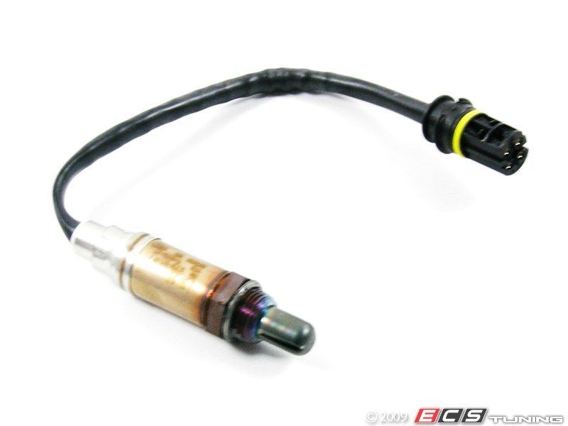
These are the components i want to build with…
Any clue or any advices ?


I think the Arduino can drive a stepper motor on it’s own, not sure if you need the red board.
I am not sure either. depending the arduino i guess.
The Oxygen sensor should give a value, depending that value and the temperature (engine) i will regulate the air intake ( mixture valve) of the engine.
The Arduino can not handle more than 40 Milliamps per pin. A very small stepper motor with no load may be okay but with any load you need the driver board. If you look on Ebay you can buy lots of stuff for the Arduino for very little money. Here is link to an easy way to get a 9 volt regulated supply to power the Arduino from your battery (they get hot running on 12 and on charge that goes up to 14.4 volts) http://www.researchcell.com/general/7809-pin-and-circuit-diagram/ If you use the same circuit with a 78012 regulator you can use that to power the stepper driver board.
A single wire oxygen sensor is also much easier to work with than the 4 wire version shown in the picture above.
Koen,
I can save you a little frustration here…but just a little.
Most of the drive by wire or electronic throttle bodies are not stepper motors but rather motor coils that turn the throttle plate against the tension of a spring. As soon as power is removed they close automatically.
The controller will need to be PWM, preferably with heavy duty external Fets mounted on a heavy heat sink. Make sure it’s a continuous duty rated design. Depending on the make/model of throttle body you will need to match the frequency of the original controller or it will respond sluggishly and will probably fail quickly.
I also considered using an electronic throttle body. I played around with a GM model using an off the shelf generic pwm and the response was terrible. It also burned up the motor after only a short while.
After further research, I believe having the correct frequency will improve the response, mine was not the correct frequency. The duty cycle is also critical. You’ll want a controller design with a variable duty cycle to aggressively move the throttle plate into the desired position, then reduce power output to just what is required to hold it against the spring tension - otherwise you’ll likely burn up the motor as I did.
I’m slowly warming up to the arduino controllers, being a PLC guy, everything else seems like experimental or hobbyist grade stuff, but I’m slowly coming around. The one wire oxygen sensors are cheaper and less complicated as Gary pointed out. If you want an AFR gauge to look at, you can get one with a 0-5VDC output. Most wide-band AFR gauges feature this for connecting to data loggers. They’ll provide you with a gauge and a data point, but they aren’t cheap, most are $200-$250 US…
Hope this helps some??/
A very easy motor solution is to use a RC (Radio Control) Servo, they are not expensive and easily controlled with the arduino. No driver board is required http://playground.arduino.cc/Learning/SingleServoExample
Thanks both for the much appreciated insights, this is all what it is about.
Here is a link towards the available arduino stuff here in Thailand, not to expensive i believe, but i have no comparing prices.
(divide the prices by 28-30 for $ )
They also have a pwm up to 50 amps, but not sure if that will work ?
The servo might be a good if even the better option. All depend from whats available of course.
Anyhow, it’s an interesting brain teaser ( as usual )
Next step is to lit the charcoal with a glow plug and use the glow plug as thermocouple to monitor
An H2 sensor to regulate the water injection
Co2 , O2 and CO sensors… ( dreaming on )
Measuring is one, being able to adjust is the other …
I have seen PWM on here so many times. I have looked in the acronym page and still haven’t found it. Can someone please tell me what it stands for?
Pulse width modulation or pulse width modulator.
A trailer brake controller is one example of a PWM.
The PWM sends pulses off the full voltage towards the DC motor ( kind of on-off switching the voltage )
With that you can control the rev’s and the torque ( pulsating instead of increasing- decreasing the voltage )
In the Throttle body you make the pulse often enough to hold the valve in position ( against the torque of the spring ) with of course the correct voltage and current to obtain the desired speed
Thanks Marvin,
So I understand it as an efficient rheostat. All the rest of it reminds me why I like plumbing. 
Thanks Koen,
That actually help even more
I like the RC car servo idea, if you go this route get the ones with steel gears. The higher end ones are plenty powerful enough to control a simple butterfly valve. Very cool idea.
This is the O2 sensor kit I last used, we are going to this kit just for this reason. It has a supplied 0 t 5v input wire. This kit is also self calibrating. I used a digital display on earlier ones and the display is all over the place the simple dial much easier to read. We are also going to manipulate timing when loading the machines via an MSD box.
You can see this O2 senser read out in action in this video here.
1 Like
Seems to be an accurate , be it expensive, AFR Gauge…
Would a simple O2 sensor be sufficient to control the air mixture ( no need for fast adjustments )
Arduino has a "knock sensor kit " and a “hal sensor kit”
I am also thinking off building my own ignition system to be used in the old Toyota diesel
( transistor trigered , 1 coil per cylinder, 1 spark per ignition stroke only to avoid pre-det from the hydrogen )
Ignition and correct mixture are the 2 main issue’s to obtain the best efficiency/power from an given fuel-engine
Anything can be build, just having the imagination for it 
Ps. Matt, can we PM ?
Absolutely
Lots useful information here http://www.msextra.com/ I was able to find a circuit to interface to a reluctor (common sensor used in place of points)
Yes nice web site, but nothing about pricings ?
edit: forgot to look into the forum pages
Nice indeed
Megasquirt is open source, I think you can get one for around $700 USD, I am not suggesting to go that way but there is a lot of useful information on there about setting up sensors etc. Also this site is worth looking at http://www.hayriv.com/arduino/gasifier-monitor
That website hayriv is great, he even has a later model, gasifier ir, with the o2 sensor and temperature…
Ive done a few tinker hobbys with arduino. Most my parts came from here
Best I can say is look into an external power supply from the arduino and only use the mili amp command signals from the analogs. Similar to controlling a Temposonic rod. Scaling the analog signal. Ive got tons of Allen Bradley laying around. When I get to that point ill be using a MicroLogix more than likely. But an arduino can still be the brains of the operations you need just have to do some off grid power seperate to the arduino.