Fluidyne Pioneer

FEMA was designed to be an expedient means to keep small agricultural equipment and trucks moving in an emergency.

My FEMA was tar factory, but in hind sight I would have liked to try that to see if it helps. .

Too me a FEMA gasifire is like Rhubarb hat, it will keep the heat off for a while, but its no long term solution.

1 Like

Sorry TomC:
In my thoughts area at the very beginning I was discussing what I thought was a good idea I have mulled about for a long time with.
A gasifire for Charcoal, only one not too choosy for its fuel with the ability to deal with tar from a low grade partial chard fuel.

Torrified wood does not need to be processed as long as making charcoal.
It’s hydrophobic and does not rot so storage is easy.
It’s more energy dense than wood but retains over 90% of the energy the of fuel wood.

It’s potential easier fuel to process since it can be cooked up in about an hour per batch at 400F.
Maybe this means I could make it in a continuous process if I made a clever retort that allowed the feed stock to slide in one the top and pulled from the bottom like a coke battery on its side.

The pioneer itself is simple and small.
Add some preheat ideas hijacked from the GEK and maybe I could widen its turn down ratio and improve its performance.

So why not take the Fluidyne or such and run your tariffed wood in it. I’m not sure what you mean by the “pioneer”? You mention it but then put up a video of the Fluidyne.TomC

1 Like

Pioneer class is the model the gasifier is based on, Fluidyne is the company.

When I click on the link I get a PDF file and short write up on it with design specs.
What do you get when you click the link?
Maybe something is wrong with the link.?

I don’t have any torrified wood and I don’t have a pioneer class gasifier.

Before I build it I want some feedback from others who have tried these things and experimented with the feed stock, preheating air and fuel bunker as well as steam injection to control the reaction.
I think thermal runaway is a real possibility just like a regular charcoal unit would face.
I have read a few places about extremely dry feed stocks causing thermal runaway in the GEK, and Greg Manning talked about it in his early preheated design too.

1 Like

Ive never looked at that PDF but that looks nothing short of an Imbert. What makes this special?

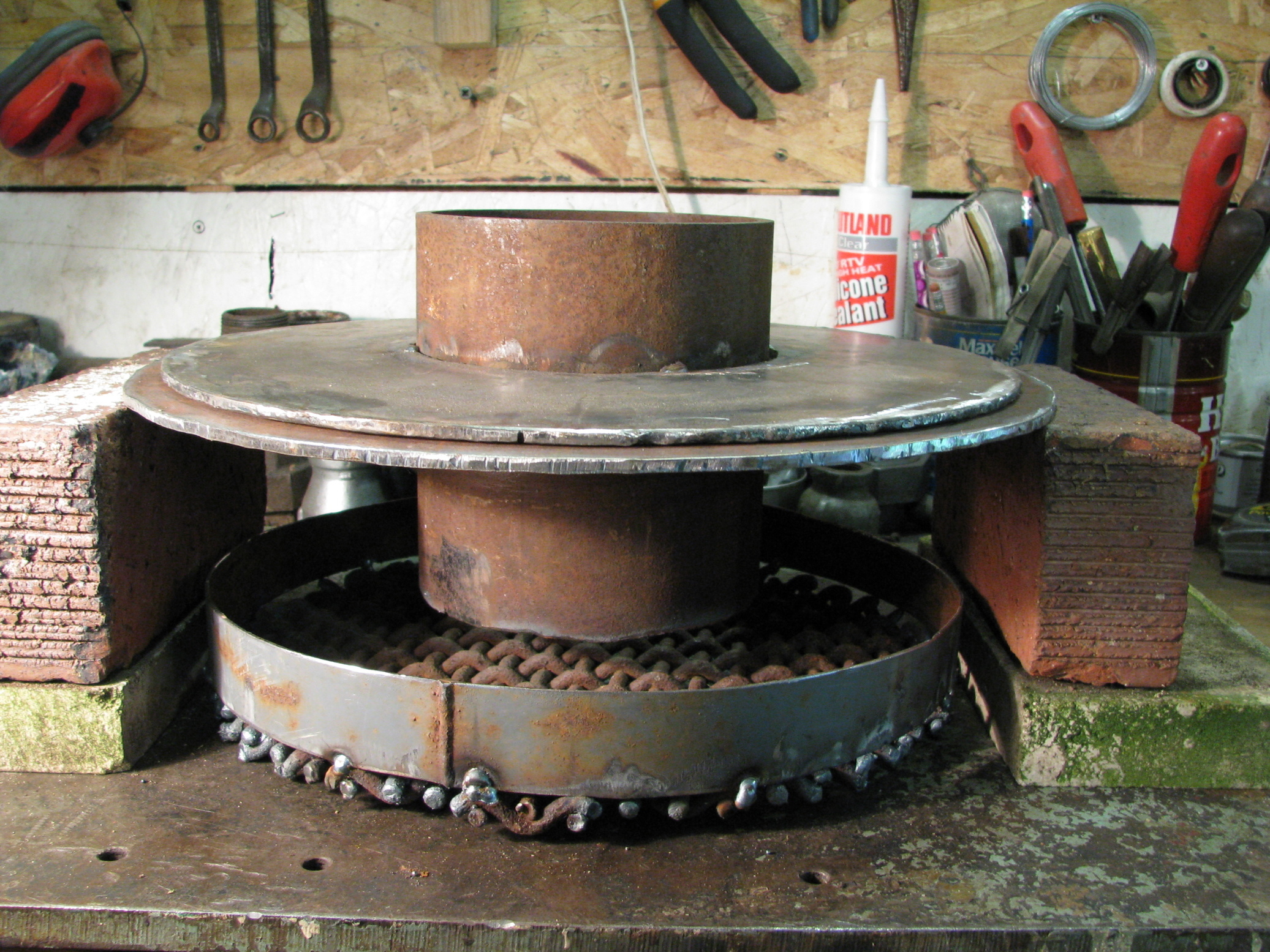
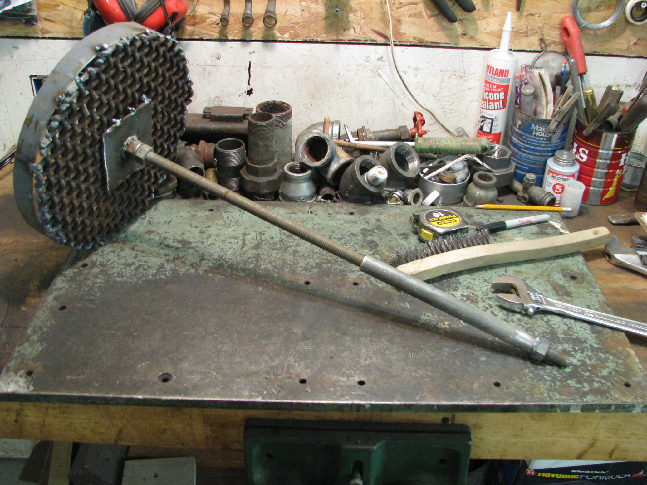
The grate is similar to ours where we are rotating it on a shaft radially.

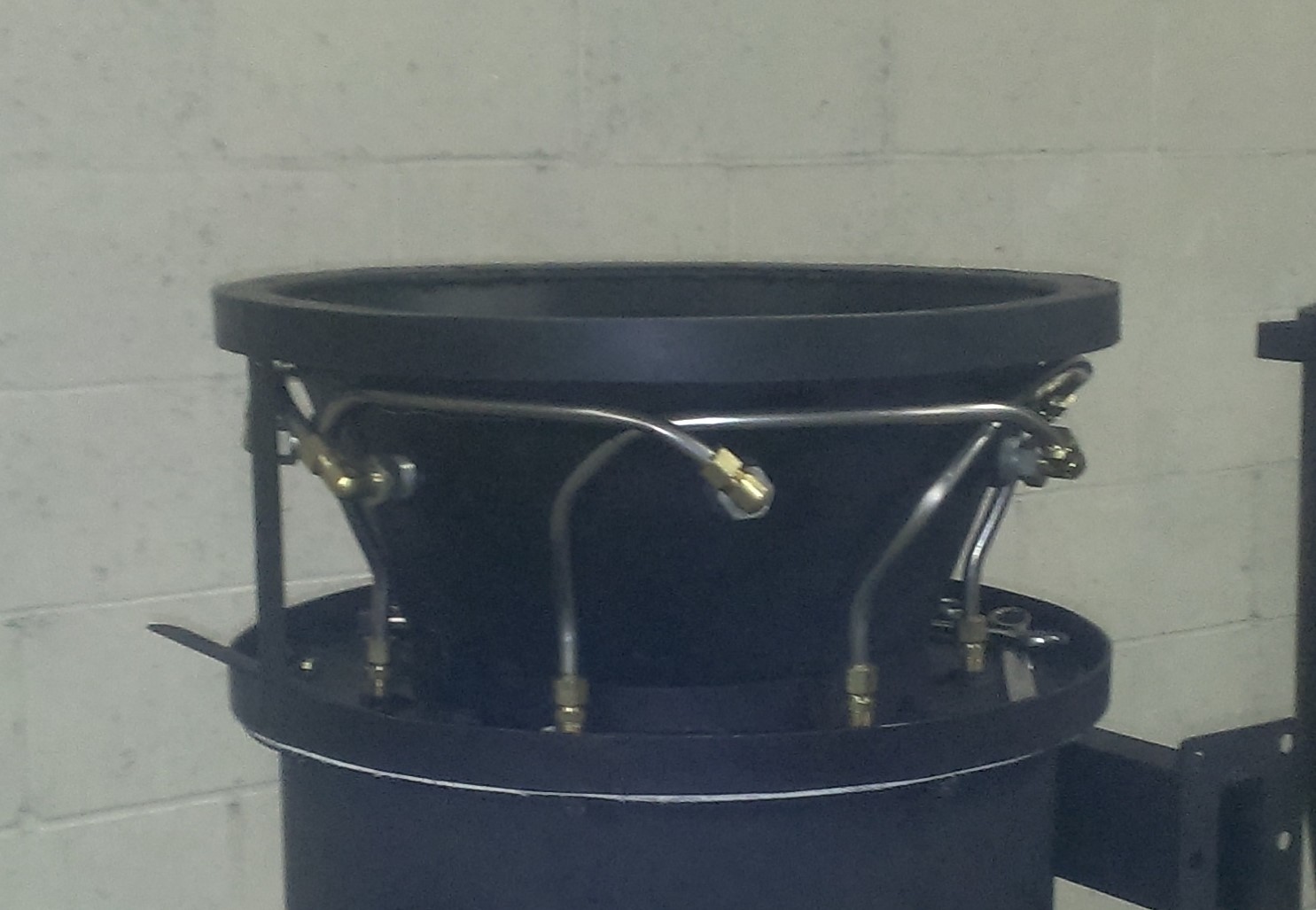
We have built very elaborate air preheats and went to simpler designs you can only heat the air up so much, and it heats up very fast. We now have a simpler baffling system and are getting the same results as before. Where we differ from any one else is our reduction system. Our reduction is now fours times the spec on the imbert chart with a hybrid cross draft grate. Our jetting is tuned slightly to match the fuels we specifically test with. The Imbert chart is just for reference, no fuels run the same pine vs hardwood vs other softer woods. Chip size, moisture, air preheating, and other aspects play a whole other part in your tuning.

To get fuels to flow in any small gasifier grate flow vs your upper raw fuels flow must match. Adding the grate and hopper agitators will correct these things and get your machine to flow. However, it must be tuned as well. The better tuned the machine the better the agitator will work.

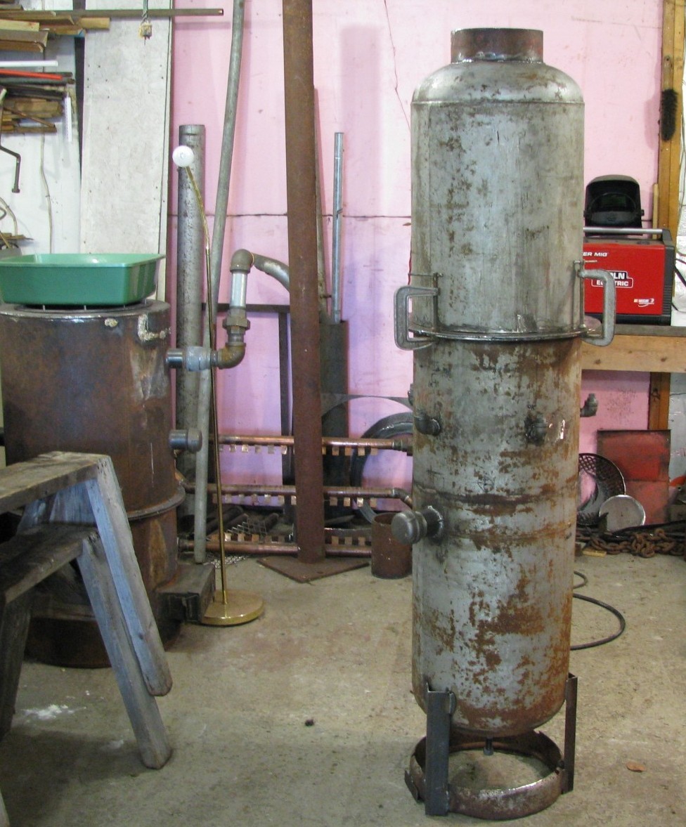
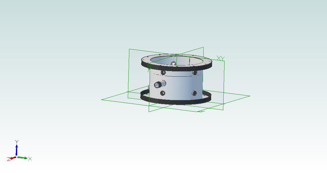
We did try creating the void very early on to stop bridging. This was the very first rev of what was the Evolution design at the time and why we had the bump out in the mid section. It didnt seem to make a difference and I wanted to try different designs. So we kept this bump out to create other designs and this has evolved into what you see today, its now there to simply make room for our jet system and to allow a place to add insulation.

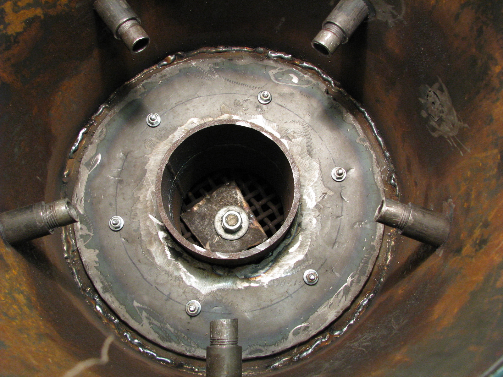
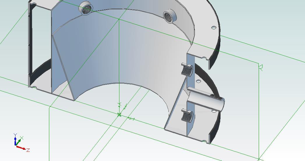
Our conical / tapered hearth is also tuned for flows at combustion. This combined with our reduction bell is sort of like the hour glass hearth systems, but we are retaining the void around the reduction bell for natural insulation build up. From here our bell also has a tapered top and is also shaped like an hour glass, its no longer an inverted cone. The side walls of our reduction have revisions for carbon build up along the outer perimeter, the lower portion then transitions from down draft to cross draft to eliminate packing, The grate design and agitator are also components needed for this work.

Pull your gas out from the side like a cyclone in reverse. This does two things, it helps distribute heat evenly while also aiding in dropping your heavy debris. Our new system with tank we hardly even need the centrifugal filter any more and this may go away in the future.

So I guess at the end of the day for a gasifier to flow, we need to consider fuel first, then design around it. Denser fuels need less reduction then less denser fuels, smaller fuels need less great spacing. A dense fuel like a wood pellets need longer jetting, jet openings typically are smaller as well. But you can always open them up. Pellets will flow well going into the combustion zone but are more prone to grate clogging. Chipped fuels are less dense so all the above are just the opposite, however, if a hopper agitator is used this will eventually effect things down stream.

3 Likes

Hi Wallace,
I started with the FEMA, read about its short comings and tried my hand at the fluidyne design. It’s as Matt says basically built to imbert dimensions. Nothing wrong with that except the 1/2" nozzle dimension and other refinements like preheated air, monorator hopper. SU advised me to start with 1/4" nozzles and increase if needed. I still run 1/4" nozzles with good results. In my vid I had neglected to fully weld the reduction tube to the flange, thus you see the redhot area on the shell. This also is called an internal leak allowing gas to by pass the reduction zone and diluting the finished gas resulting in a lower quality gas and “passing through some tars”. Then I caught up on my reading and learned about preheat, etc and went into my present imbert build. Here’s a few pics and vids of my fluidyne. By the way I used tree branches from 1" dia to 3" dia, cutting them as long as their diameter. I use this same size for my GEK variant and it works well. Check out the rest of my posts once you’re on the site.
I would relegate the fluidyne to experimenter status and move on to the imbert as I did. How were you going to preheat your air. Same question I asked myself, so I went whole hog on my present unit. Yes it’s more involved, but it is time well spent on a proven design and a great learning experience. You’ll get a better quality operation and gas, imho. I was able to salvage much of the fluidyne to move on. Good luck in your quest. Don’t hesitate to ask questions, we’ve all been there at some point.
Pepe

The large plate holding the grate interferes with the free flow of gas and a “cool” spot which may inhibit reduction therefore gas quality. I used a “just big enough” round washer on the next tear down.

Note the FEMA in the left background. It was good for getting into gasification and back into welding, but has many drawbacks, notably tar production. The fluidyne seemed a logical step up in terms of ease of build, but as I said, still not taking advantage of preheat, etc.

Checkout my journey in the Forum, “My first small engine run”. Hope this helps.
Pepe

4 Likes

Matt the Pioneer is nothing special, its just small, adjustable and has a track record of working.

Matt, how do you accomplish your air preheat?
It should be easy to run a counter flow system and achieve 60%-70% heat transfer without much trouble ( on par with a medium efficiency furnace with the same thermal output ).
We managed much higher numbers at large scale at my former employer running a Bessemer based converter ( and you want see a dust load ).

I need to look at your videos to see if I can understand some of the other ideas you bring to the table.

And thank you Pepe for showing off your system, Its nice to be able to pick your brains and get suggestions too.

2 Likes

haha unfortunately I cant show all. Open sourcing dont work, people still steal your work. Once we get patents Ill open up more.

But for the preheat its really nothing special. The pictures the CAD model of the current Flex R1 much simpler, yes it could be better like our older versions but for the amount of work and cost, this is the better option and works good enough and it has performance advantages over the older version as well.

On older versions we had two air preheat systems. First stage had a very elaborate baffling that wrapped around the reduction zone, we added the secondary system later on (pictured below). When we evolved to the next generation systems we scrapped this primary preheat and left this secondary preheat system in its place.

Where the advantage of this is and why I believe we dont need it to be that elaborate. At lower loading the air is entering at a slow velocity giving it plenty of time to absorb heat. This aids in adding to the turndown ratio. At higher loading, the air velocity is increased but will absorb less heat. Not an issue because at higher loading the machine has no issue maintaining temperature. In the higher loading the air does not get as much heat and is denser. This is good because it helps the machine breath better at higher loading.

See pictures below, this can be adapted to the Fluidyne quite easily as it is a similar design. Ill try and find pictures of the exterior jetting.

2 Likes

On the Fluidyne design leave it as is with the exception of making that reduction zone much bigger. Build it with the same desing concepts but open that up after the restriction and give it a good 6 to 8 inch skirt. The grate on the center shaft like that you can then make it so you can adjust it to different levels.

If you can build it so you can do this on the fly you will need to start out with it all the way up and tune it down. Ive been down this road, and once its adjusted down its not very easy to bring it back up.

3 Likes

Pepe I was thinking about your design and the leak internally,

Ever try some converter clay to plug it up?
Its rated for far higher temperatures and you can chip it out after ( refractory material used for plug in metallurgical furnaces so the plug has to come out for tapping )

1 Like

This is the only picture I could find of the jet piping. We no longer hard pipe, we use JIC fittings with the SS flex hose.

6 Likes

Great insights on the temperature of the air needing to be higher at a low flow and lower at high flow.

Thank you very much Matt.
This is very useful information.

The CAD drawing seems to show two sets of Tyvers ( not sure about the spelling of that )one set above the hearth restriction ( where I would expect ) and one below.

Personally, I won’t take heat from the reduction zone as I believe it needs the heat for the conversion process. Even still our system uses a double pass to pull as much heat into the incoming air. Not complex to build but nozzles are not removable from outside the machine. I think a victoria is as simple a build as any for experimenting and it’s very refined in its simplicity… just my thoughts on the subject…

1 Like

Indeed the bottom set is for piping up to the top openings where you will install the jets.

@Arvid, this wasnt quite all the way below the reduction bell on early gens. The primary stage started at the bottom of our reduction bell and then transitioned into the hearth. Yes totally agree with you on that, that is why we have the new revision for regenerating the insulation in the reduction.

3 Likes

When I tore this one down and found the leak, I was ready to move on to the imbert. I have tweeked the imbert to the unit I have presently, my beta baby. I have never tried converter clay. I’ll check it out.
Pepe

1 Like

Are you looking for the word “tuyere(s)” Tuyere - Wikipedia ?

We just call em jets, no need to be fancy its just a gasifier hahaha. :fire:

3 Likes

tuyere Ya I know the word its in common usage in my work, but I never have been asked to spell it lol ( I also speak a little french and that also does not help me spell it )

Use of JIC fittings is an excellent idea.
I was thinking the same thing but using common steel pipe ( just because its easier to bend )

Clever ideas I see here

2 Likes

This is what we use, these are kinda of expensive but if you value your time than this is cheaper in the end. You might be able to find them else where for less cost.

We tap the opposite end of the JIC fitting with a 3/8" NPT tap to make it accept a 3/8 pipe cut to length. The open of the 3/8 pipe is then tapped for 1/4" NPT and we install a socket plug in it and then drill to whatever jet opening we want.

2 Likes

That gas pipe is something I have been looking at.
Not sure if I can buy that here ( likely need a TSSA number for purchase )

Some years back I made a crude flare tool that let me make a thin gauge tube flair that sealed.
Might be more work but its obtainable.

1 Like