Omnifueled Gasifier/Air-Water-Heater Energy System
Introductionby Larry Dobson
This gasifier design is the culmination of my 38 years of work in the field. It will solve many of the problems that now plague those modeled after the old WWII Imbert gasifiers. While many recent improvements have been made by dedicated gasifier enthusiasts, it is still an evolving technology, with much scope for new approaches and improvements in the utilization of huge quantities of locally-available waste biomass fuel sources. Biomass- and waste-fueled energy has the potential to contribute much more to global green energy demands. To learn more on this subject, read my Department of Energy report on “Biomass Energy, State of the Technology, Present Obstacles and Future Potential” at http://www.fundamentalform.com/html/doe_report-1.html
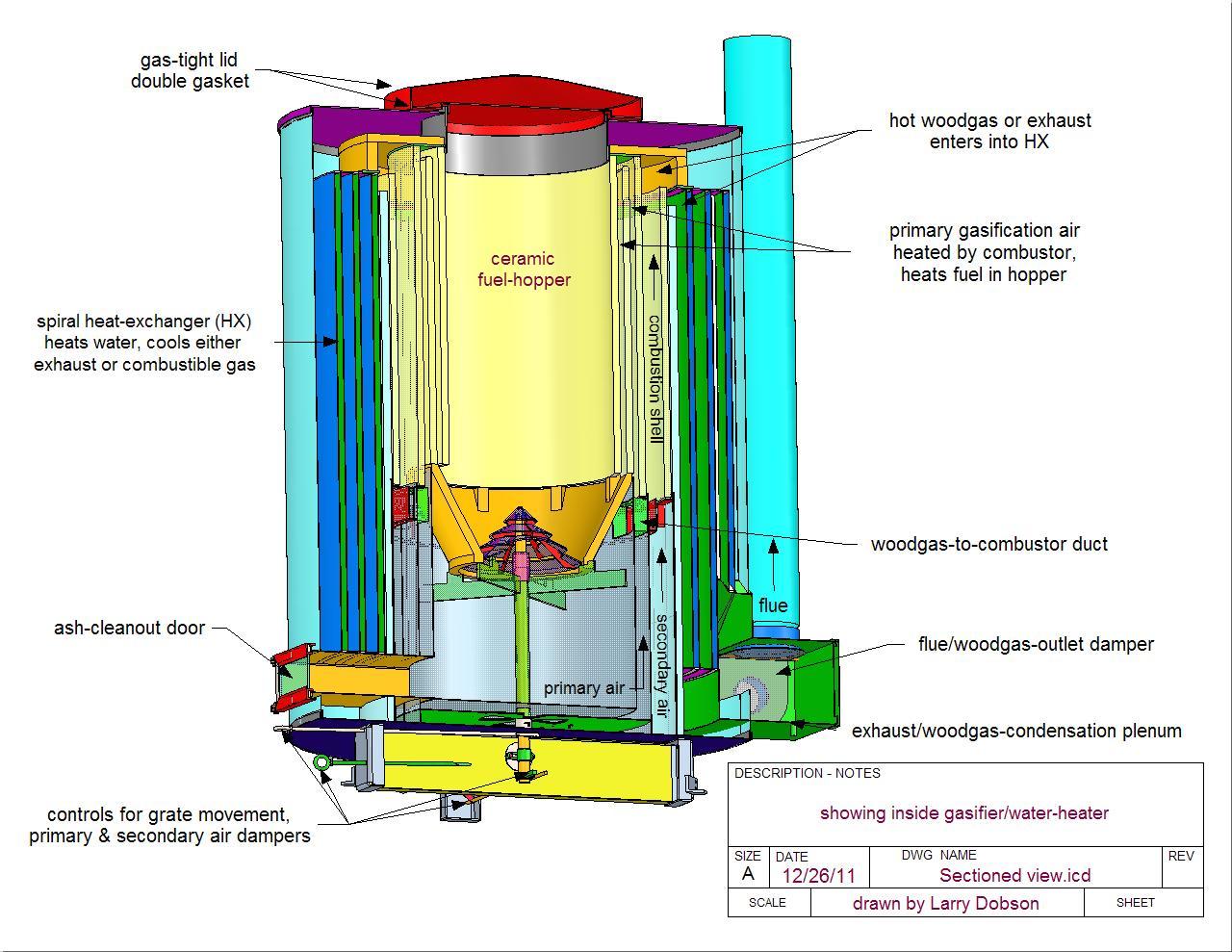
The above drawing is a 120,000 Btu/hr biomass-fueled gasifier/hot-water-heater. It can be a stand-alone gasifier, heating water by cooling the gas, to be used to fuel a genset or other gas appliance; or it can be a waste/biomass-fueled hot-water furnace, burning the gas internally, with high efficiency and cleanliness of burn.
This is a completely new design, based on the best of my previous prototypes. Most of my earlier prototype gasifier/combustor systems were based on a rectilinear side-draft gasification flow through a narrow fuel column into a close-coupled combustor surrounded by a ceramic heat exchanger that preheated gasification air, even using fuels with up to 2/3 their weight in water. For more details on my previous work visit my website.
This prototype embodies optimized gravity flow principles that follows more elegant thermodynamics than previous approaches, through an interweaving of concentric shells and spiral ducts. This latest design, embodied in both a gasifier/hot water heater and a gasifier/hot air heater, named Roundy Water and Roundy Air, are sized for a large household, 120,000Btu/hr, 35kWe, which will heat water for heating needs or generate electricity through a genset fueled from the gasifier.
Roundy will put out substantially more than 32kWe when responding to an internal combustion engine vacuum. I expect a very large turn-down ratio, at least 20/1 in combustion mode, with very high efficiencies in condensation mode, perhaps 95% of the High Heat content of wet fuels. Most furnaces are rated at Low Heat (dry weight basis) efficiency, discounting the moisture in the wood, since condensation does not occur, thus losing the heat of vaporization. So a 100% efficient furnace is still passing steam-heat out the stack. Since green biomass can often be half water, and the other half of bone-dry wood combusts with more Oxygen from the air into more than half its weight of additional water vapor! This represents a significant increase in energy available from condensing the woodgas or exhaust. This and the exhaust-scrubbing advantage from condensing the exhaust is the reason the heat-exchanger on this furnace is so large (150 sq.ft.).
This unit will create a high quality gas, clean enough after the condensing heat exchanger (CHX) for the engine without further cyclone separators or filters. There will be an operating range where the gas is the cleanest, and another condensing range where efficiencies of both gas and hot water production are highest, and an upward range where exhaust is too hot to condense. These parameters will all be tested to optimize this technology for manufacturing.
Any fuel that will fit in the hopper and produce a combustible gas can be gasified ~ logs, chips from the tree trimmers, bark, sawdust, corn cobs, leaves, wood-, straw-, municipal solid waste-pellets, green and wet biomass (up to 2/3 water in the furnace mode), household and farm waste, etc. Ideally, anything that will burn can be vaporized or gasified and turned into a fuel.
A quality fuel gas contains mainly Carbon Monoxide (CO) and Hydrogen (H2), combustible gases, along with the 79% Nitrogen (N2) from the air and the considerable water vapor (H2O) generated by the combustion chemistry as well as held in the fuel. Generally, the Nitrogen Oxide (NOx) content is very low, and soot, hydrocarbons and other smoke pollutants are non-existent. The steam will condense on grains of fly-ash and the cleansing rain will scrub the gas clean in the condensing HX.
The difference between ideal and practical has been significant in the history of gasification, largely because waste fuels are not homogeneous and measurable like gasoline and natural gas. The pieces gasify at different rates, and the difference in moisture, ash, elemental composition, slagging temperature, oxygen and CO2 penetration of the coal-bed, feed considerations, etc. present many uncontrolled variables. These challenges have been grist for my explorations into this technology. Roundy has been designed from the following
Observations & Discoveries
- Fuel in a hopper gasifies best and most evenly, without bridging, when it is burned, vaporized and gasified evenly at the base of a vertical-sided hopper. Whenever there is constriction without size-reduction from burning or gasification, as is often the case in the upper throat of an Imbert or constricting throat gasifier, where combustion doesn't consume the fuel to the contour of the throat, bridging and uneven gasification occurs.
- Whenever there is bridging of the fuel, air supports combustion beneath the bridge, creating hot flames and a spent gas with excess oxygen and little if any energy value. If the bridge burns through, the gas is greatly diluted and cooled by excess air, which can totally rob the fuel gas of energy. Then the bridge collapses, quenching the flames and heat with cool damp fuel and steam, creating a burst of sooty gas, followed by diminished cool gas production.
- Providing the above feed conditions are addressed, preheating the incoming air can almost entirely solve this problem, if it is hot enough, because the endothermic gasification is sustained in a deeper coal bed by the high-heat of a lesser volume of air. This is quite different from conditions created by a larger volume of cool air, with its oxygen content creating combustion to supply the heat along with lots of diluting nitrogen and CO2. With this approach, higher-energy-content-gas can be created.
- Of the three fundamental thermodynamic ingredients of Time, Temperature and Turbulence, Time is too often neglected in favor of Turbulence, as in the jet of speedy air shooting from the tuyers of a typical downdraft gasifier. I have found it better to let the air slowly permeate the fuel, heating up a large mass of fuel slowly, evenly, creating a large hot coal-bed, letting the gas become saturated with CO and Hydrogen over time and temperature. Instead of turbulence for mixing and HX efficiency, Roundy has been designed for laminar and internal vortex currents propelled by natural convection flow.
- Steam and CO2 are primary combustion enhancers, speeding heat transfer significantly by their bipolar molecular property of absorbing and radiating radiant energy. Radiation is the primary mode of heat transfer at the temperatures of gasification. N2, O2, CO and H2 do not absorb radiant energy, so heat transfer must come from neighboring bipolar molecules or be delayed.
- Steam and CO2 also react with the charcoal, creating CO and H2, both fuel gases. The best gasifier utilizes these reactions optimally, along with preheating the fuel and air, for a high energy gas. An exciting potential from this revolutionary technology is to increasing the energy content of the gas considerably through supplying more heat to drive the endothermic reaction that creates this conversion of waste gases into fuel gases. Average wood-gas has around 300 Btu/cu.ft., whereas the combustible gases in it, CO and H2, have energy contents around 1000 Btu/cu.ft. There appears to be no theoretical limit to how much water can be turned into fuel gas, as long as temperature and time are sufficient for the reaction.
- Contrary to expectations, adding all this heat and insulation does not deteriorate the materials of construction as much as allowing local hot spots of 2500-3,000⁰F combustion, which is far above the required gasification temperatures of 1300 - 1600⁰F. Temperatures above 1500⁰F rapidly oxidize metals and thermal-shock ceramic, as when cool fuel suddenly lands on orange-hot refractory or cool air rushes in an empty open hopper.
- Solid fuel gasification and combustion produces ash, which collects on all horizontal surfaces, blocking passageways and requiring cleaning. I have designed this gasifier/furnaces/heat-exchanger with only vertical surfaces. Built into this unit is also a surface-cleaning system utilizing air and water.
- The hopper and entire construction is cylindrical, creating more even feed and flow, less thermal stress, simpler construction, more reliable seals, thus the name "Roundy".
- When burning the gas to heat water, the generated gas is burned in a concentric combustion shell, which feeds heat to the incoming air and fuel in the hopper, augmenting the calorific value of the produced gas, thereby requiring less air for more gasification of a higher quality gas, which is mixed with preheated air and burns super-clean in the combustion shell.
- Highly preheated gasification air is introduced to the preheated fuel around the base of the hopper, where it is burned and gasified, creating a steady-state fuel feed without disruption of the fuel. Residence time of all heat transfer and chemical reactions can be much greater than conventional practices, which greatly expands fuel options.
- Any fuel that will fit in the hopper and produce a combustible gas can be gasified ~ logs, chips from the tree trimmers, bark, sawdust, corn cobs, leaves, wood-, straw-, municipal solid waste-pellets, green and wet biomass (up to 2/3 water), household and farm waste, etc. A conical grate at the base rotates to dump ashes and break up any bridging. The grate can be activated more frequently to collect biochar with the ash, instead of turning it into more H2 & CO fuel gas. Biologically-activated biochar is a major discovery in soil fertility, which can make the family farm more productive, just from the waste biomass accumulated around the farm. It must then be inoculated with mycelium to become activated for plants.
- Although this first prototype will be operated manually, We will incorporate a microprocessor control system in production models to monitor gas quality, changing conditions at the base of the fuel column & rotating grate, preheated air and other temperatures to operate dampers and fans and optimize gas generation quality and quantity, dramatically reduce thermal shocking & metal deterioration, and can also be adjusted to create maximum biochar production instead of CO + H2 if desired.
Air and gas flow throughout this system is governed by fundamental principles of gravity, temperature and density.
- When a fluid is heated, it expands, gets lighter, and travels upward, augmenting natural draft.
- When a fluid is cooled, it contracts, gets heavier and travels downward, also augmenting natural draft.
- When these principles are adhered to, the strongest natural draft is facilitated, pumping throughout the system without a fan (although one may be incorporated for starting and increasing the throughput and responsiveness of the system.)
- When these principles are applied in a counter-flow heat exchange, the hot fluid being cooled flows fastest downward next to the heat-exchange surface, and the cool fluid being heated flows fastest upward next to the heat-exchange surface. This increases heat transfer greatly by decreasing the boundary-layer of insulating fluid next to the heat-transfer-surface and allowing gravity-stratification, which increases efficiency as throughput is reduced, increasing residence time for greater temperature gradient. This principle is extremely important for efficiency, quality of gas, cleanliness of burn and greatly extended turn-down ratio. This means that a larger system is actually more efficient when turned down.
- Adhering to these laws of flow means that the most efficient system has the exhaust exiting from the bottom of the furnace, not the top, and the natural draft created throughout the system can be so strong as to eliminate the need for a tall chimney.
- even with a fan, gravity-stratification improves efficiency until the speed of the fan causes too much turbulence in the passageways for gravity-acceleration to occur.
- I have operated a hot-air-furnace at 200,000Btu/hr on convection flow alone, where the cooled exhaust was condensing large quantities of water at 130⁰F, while the heated air was exiting the furnace at 430⁰F. This is impossible when turbulence takes over.

Refer to the above drawing for orientation.
- Primary air for gasification enters through holes in the periphery of the bottom plate & travels to the rotating air damper in the center of the plate above. This removes heat from the bottom plate and bottom of ash-shell, preheating the air. The air then travels up outside the ash-shell, extracting more heat, then enters the ceramic duct next to the combustion shell, where it is heated by the burning gas (or 1400⁰F hot producer-gas), rises up over the ceramic shell to the inside, then travels down next to the cooler hopper shell, heating the fuel inside as it flows.
- The hot primary air exits at the base of the hopper, where it volatizes the fuel and moisture and burns it until the oxygen-starved gas travels down through the coal bed. The chemical reactions at this point are all endothermic, taking heat away from the hot gas and charcoal as more combustible CO and H2 are liberated. There are many variables for different fuels, so we may develop several modular grate designs for diverse fuels, to provide an even gasification rate through a uniform coal bed of the depth to optimize woodgas production or biochar. The fuel gas can be generated cooler and wetter and sootier for direct combustion --- it all burns clean at the right temperature and residence time, with the right amount of air mixed evenly. Within the turn-down range of super-clean combustion, there will be an optimum range for production of a clean gas for I.C. engines, phase-change refrigerators, and other such remote applications.
- The cooler, but still hot, woodgas (producer gas, biomass gas, garbage gas) exits from the hearth through the central conical grate, between conical slats that provide large openings that prevent the fuel from falling through because they provide overhanging ledges. This design has proven quite superior to just holes, which let through small aggregate fuel particles and easily get clogged with charcoal and ash. The grate is adjustable up and down to optimize the charcoal depth, and can be agitated by turning to drop out ash (and biochar if that is also wanted). Ash collects below, where it can be removed through the front access door.
- The hot fuel gas then flows through the four woodgas-to-combustor-ducts at the top of the ash bin. Most of the ash is deposited here, since the gas must turn 180 degrees to flow upward, while the ash falls with gravity.
- In the annular combustor ring, when in combustion mode, the hot gas is mixed with secondary air, where it burns cleanly due to hot temperature and even mixing of gas and air. The secondary combustion air enters two dampers in the bottom plate, where it is heated by the primary air shell, also cooling the lower region and saving on insulation.
- The combustor preheats the primary gasification air, which creates a higher quality gas while lowering the temperature of combustion, which reduces deterioration of materials and lowers levels of NOx pollutants. The outer shell of the combustor is insulated from the HX to facilitate optimum combustion and maximum HX efficiency.
- If the system is being operated as a gasifier, no combustion air is introduced and the hot producer gas performs the same heat-transfer function, although not as intense as when combustion is present.
- At the top of the combustor the exhaust or producer gas enters the spiral HX through an annular duct, which distributes the gas evenly around the entrance to the HX. The spiral HX consists of a spiral air duct with a larger spiral gas duct in between. The gas is cooled by 150ft2 of air-cooled surface area, which causes gravity stratification of the gas as it gets denser and falls next to the water jacket, while the opposite flow occurs within the air. Under most operating conditions water-vapor will condense before the exhaust or gas exits, thus retrieving the considerable heat of vaporization and scrubbing the fly-ash from the gas in the most effective filtration method available, where each tiny particle becomes a nucleus for a drop of "rain" to condense around and fall out of the gas stream. When operating in this condensing mode, the producer gas can be directed straight to an internal combustion engine without the need for further filtering.
- At the lower outside exit from the HX, a flue/gas-outlet damper directs either the exhaust up the chimney or the producer gas out another duct to an I.C. engine or whatever other appliance can burn the gas. Condensate water is drained out at the base.
- The interior hot zones are either cast-ceramic or high-chromium stainless steel, #304. I have incorporated ceramic parts in the hottest parts because my experience has been that stainless steel deteriorates too fast. If testing proves that the gasification reaction can be kept relatively cool, (under 1500F), then the ceramic may be replaced with a high-temperature stainless, like #310, which will allow a lighter and more compact unit, especially when manufactured with optimum materials and thickness.
- A manufactured version might weigh 50% less. This furnace will weigh around 1400lb, with 512lb of that being refractory ceramic. This is heavy compared with most gasifiers, but lighter than the best wood-fueled hydronic hot water heaters (Garn 1500 = 3,200lb at $16,000; Tarm-30 = 1,080lb at $6,000 (600F stack); Greenwood Model Frontier CX = 1480lb. To put things in perspective, consider the advantages of being able to produce both hot water and woodgas at higher efficiencies and cleanliness, with a greatly extended range of usable fuels and energy output.
- This design, with all the interrelated heat-feedback features, is where I want to begin testing, but many design variations, degree of refinement, much larger and smaller units, vehicle gasifiers, etc. are possible, We will undoubtedly find areas for future improvement, perhaps grate modification for specific fuels, coal bed-grate configuration adjustments, improved cleanout features, addressing thermal deterioration of critical metals, flow optimization and other preliminary details to be refined down the road, but building and testing this first prototype will give us a wealth of data, prove the superiority of this technology, and open up many new opportunities for new products.
Warm regards, Larry Dobson [email protected]
For more information, visit Larry's website: Fundamental Form | Biomass Gasifier Breakthrough Fundamental Form | Energy From Waste
This is a companion discussion topic for the original entry at http://dev.driveonwood.com/library/dobson-gasifier/