My first small engine run

Hi Brian,
I did have some reservations about using the furnace cement. Having never used it, I wondered if it set up really hard like you described. I think I’ll pass on anything brittle. Thank you for the heads up.
Pepe

I just picked up some garage door shipping crates today and got these items gratis from my book keeper wife’s boss at a major overhead door company here. Wow, rolling machine jumped out at me. 40 ’ of chain per unit. The gears in the last pic are cast together as a unit. Thank you, Scott.
Pepe


nice find and the price is right

Hey Pepe, I’ve been meaning to ask and keep forgetting to… how many hours a season do you put on your gasifier?

Stay well and keep burning

Hi Arvid,
My burn time is low mainly because I’m still in the hobby stage. Yeah after all this time! I would guess only 20 or so hours. I finally have a 13 hp generator so I expect more run time this “season”.
Pepe

Hello Fellow and Gal gassers,

Darned if the beta version isn’t a lot of work, but I love seeing it come together.

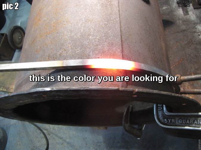
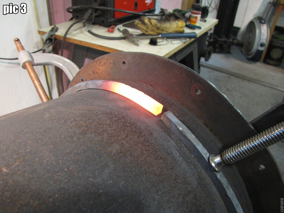
pic 1, pic 2. I used 1/2" square stock for the heat sink rim. Draw a line around the shell with a compass. Clamp bar on line, heat to brilliant orange almost yellow keeping a light steady pressure on the bar. When the temp is just right you will feel the bar start to give (bend). Spread the heat out and the bar should wrap in place, Keep the bar on the line while it’s hot. Maybe a hammer rap to help it conform.
Pepe

pic 3, pic 4. Finished blank for heat sink rim. Use a straight tank for a form if you have one. This was tight getting it over the flange, almost deformed it.

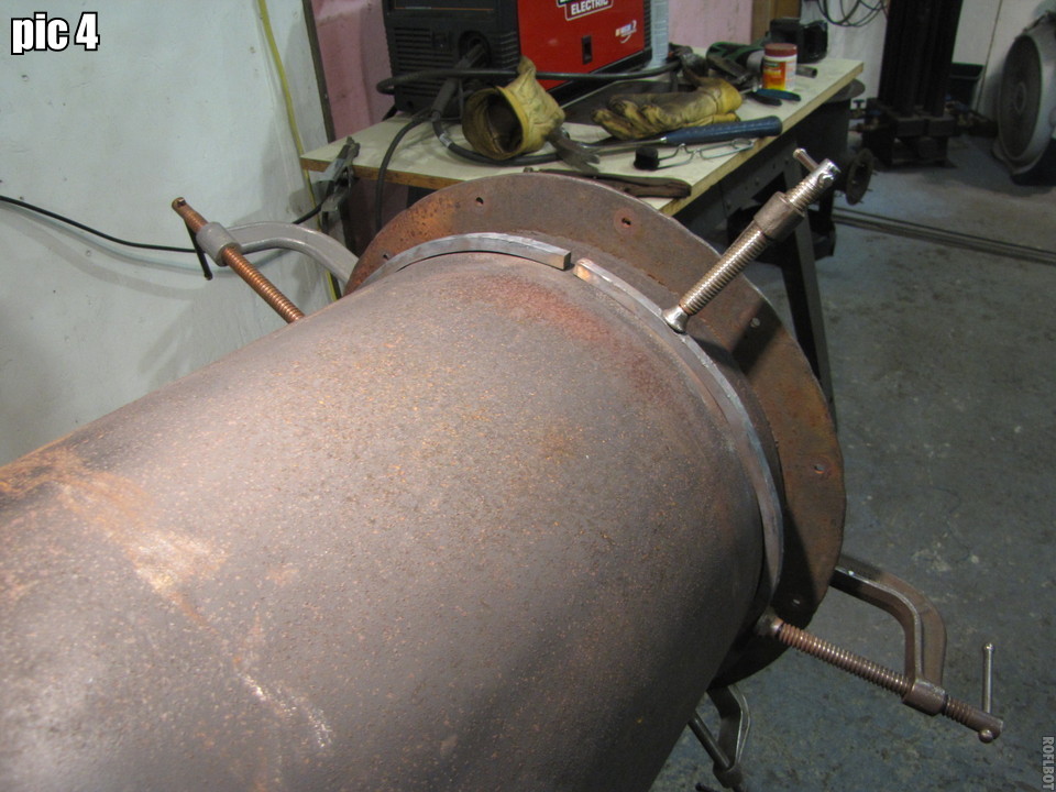
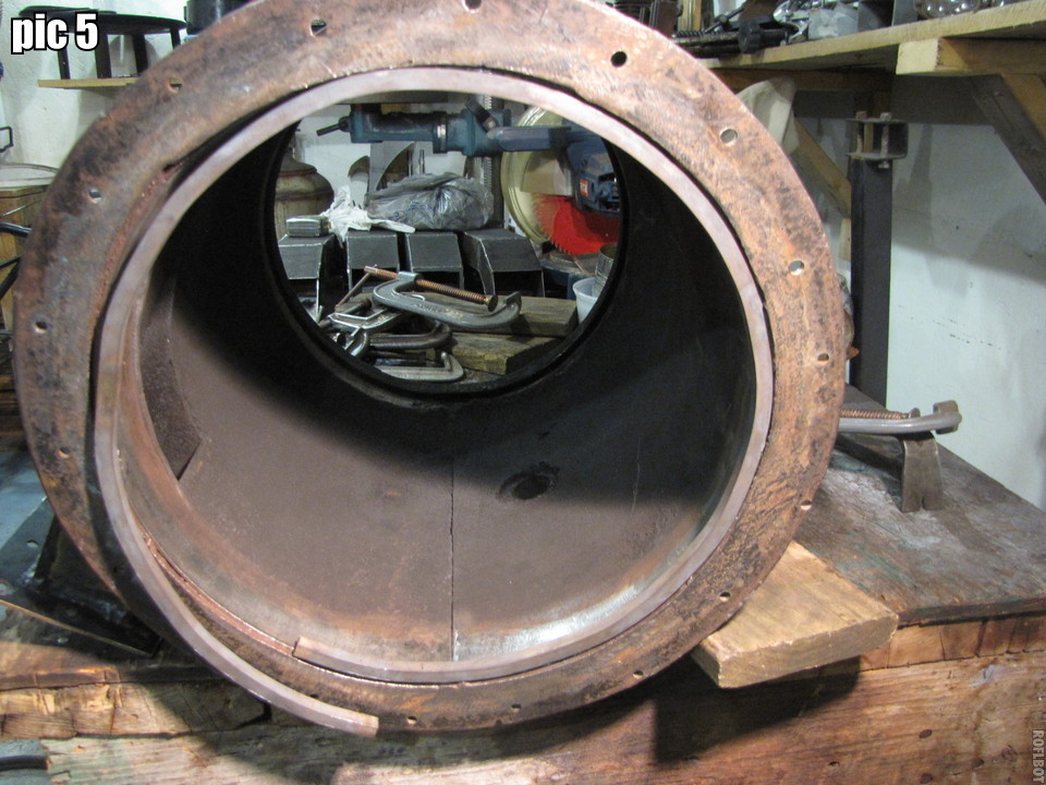
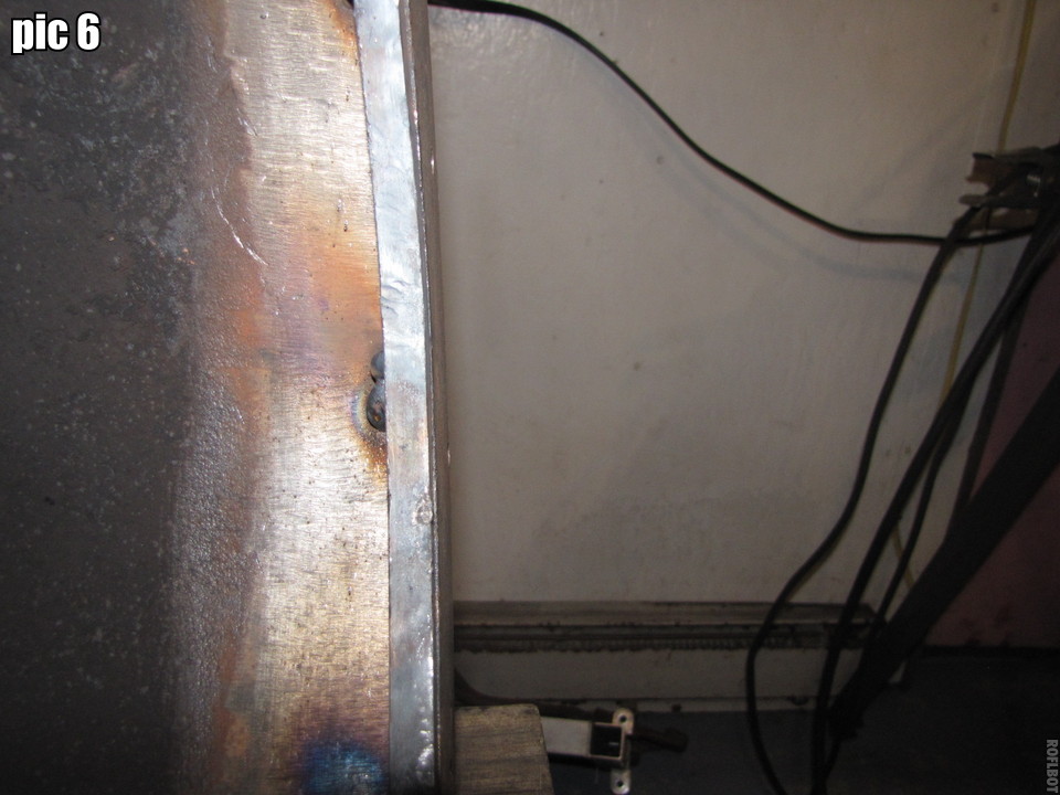
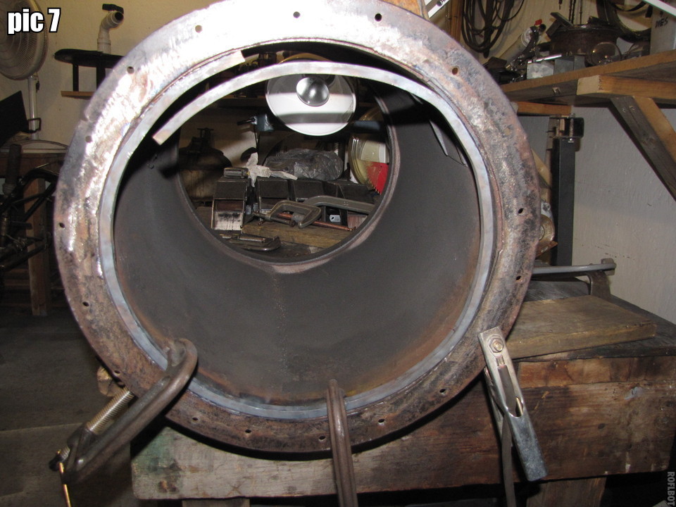
pic 5, 6, 7. Insert ring into burner tube, adjust it flush with the top of the flange holding it with clamps. Tack weld there. Move around the rim, heating and beating to conform and tack welding til done. You can see now how the inside cut of my flange doesn’t meet the inner tank circumference evenly. I had to struggle to get started as I wanted to keep the heat sink inside the tank and it kept slipping up.

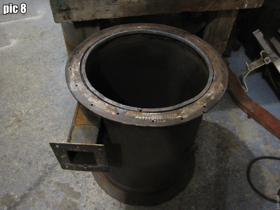
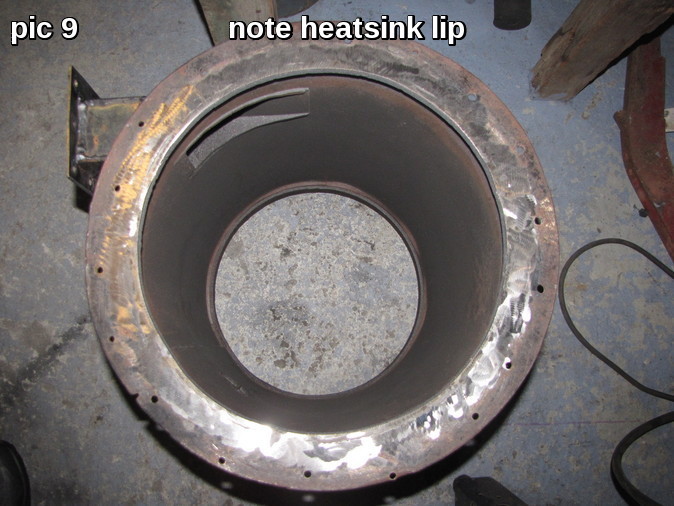
pic 8, pic 9. Now to fill in the spaces and grind the welds flush with the flange.

Can someone tell me how to rearrange my photos in order. I posted them in order but they didn’t upload that way and I can’t figure out how to get them in order.I don’t want to make a mess of things.Thanks,
Pepe

Hi Pepe,

They’re just text links in your post. You can move the text around and it will rearrange them. You can also put text in between them.

Hi Chris,
Thanks a lot. I do remember reading they were text. It is a little cumbersome keeping track of where to move them to with all the code, etc. Is there a reason they don’t upload in the original order?
I love the new program, video thing is great! Thanks again.
Pepe

They probably all upload at once, meaning the smallest will go first. If you want to upload them in order the first time, just do one at a time.

Try drag-n-drop too, it’s pretty easy that way. Open the file folder and drag them in one by one. Each one will show up wherever the cursor is when it uploads.

Thanks Chris, I thought the file size affected the order. I’ll try your suggestions. I might even try putting just a caption then the pic under and continue story book like. It’s fun anyway.
Pepe

Hi All,
Moving on to the heatsink flange for the hourglass hearth. I made up a simple compass to layout the heatsink ring on a leftover circle from a previous 1/4" thick flange cutout. Note the original center and layout lines scribed into the original 24" x 24" 1/4" plate steel. I got the ring over the top of the hearth and turned the hearth upside down. I then tapped the ring down to the edge of the hearth. I spot welded the ring to the top of the hearth and gently beat the hearth to conform to the ring. I welded both sides for additional mass. Hopefully this will save the hearth from distortion or melting. See that hearth heat damage in post 315. Use green box in lower right of page and type 315, hit enter, bingo, you’re there. To get back, go to green box and click bottom to get to the last post or enter another post number. Resist using the back button, it will bring you somewhere else. How do I know 13 times now? If that happens, hit your mouse forward button and go to the green box again.
Pepe

I just noticed what appears to be a vertical crack in the weld seam on the upper part of the hearth. The hearth is upside down in pic since I had just tapped the ring down to the edge. I’ll check it out in the morning. Never stop inspecting!
Update- The weld is fine.

The ring forced a pretty good circle out of the edge.

The fit is very good. There is still enough room to add sand as an insulating material between the hearth and the burner shell. It’s an optical illusion that there appears to be no gap at the top of the pic. Also note the gradation of color from top (black tarry) down to the tan (pyrolysis zone) ring 4" or so above the nozzles. I like the temperature driven zone division example.

I’m going to turn my attention back to the grate and remove the solid fence. This will be replaced with a taller heavy screen fence. This comes after reading Jim Mason’s GEK 5.0 revelations. Thanks Jim and team for an amazing “turn” of events. I figured I’d get a similar longer residence, higher fuel density if I had a larger volume of char similar to the grate basket shown here.

I just refound this pic that shows a cast in place grate basket circa 1970. The article is in the History category titled “Early woodgas from Australia”, post 14. Love the post numbering system. Go to Forum, on the upper left side of the screen click on All categories, then click on History scroll to “Early woodgas from Australia” post 14. You can enlarge the picture there for a better view of the “grate basket”.

My basket will take up most of the “H” dimension of 4". Probably 3 1/2" as shown by the cross sectioned grate.

Update- The diameter is 13 1/2". I used a 3" wall. The original wall was 2" so this increased the volume from 286 cubic inches to 429 cubic inches or 50%.

This grate wall will go.

The new grate basket wall will be made from this heavy screen. Since my grate is 13 1/2" I can use a small properly emptied propane tank to heat form the new grate basket.

2 Likes

Is that old grate a cast iron floor drain cover?

1 Like

Hey Pepe,
I like the idea. I have an abnormally long reduction tube and I am experiencing almost no char to speak of after a good run. My grate seems to breath good too with no shaking. I think the char in place helps because my temps leaving the gasifier into my drop box are only around 350 F (temp taken externally on pipe)and my temps in the hearth are 2000 +. I think you will find that your char held in place will give you more gas and less char for cleanout… Just a guess. I can’t wait to see it go! Gordon

1 Like

Hi Bill,
No, it’s a piece of 12" diam 1/4" mild steel I carefully cut slots in. So far it has held OK.

Edit- Sorry Bill, the piece is 13 1/2" to fit into a 100 lb propane tank with a 1/2" space all around.
Pepe

1 Like

Hi Gordon,
I was experiencing quite a bit of over spill of charcoal into the base, that’s why the original 2" solid wall. Carbon that doesn’t make it to carbon monoxide. I’m thinking this is a sure plus. I’m getting anxious for a firing, too. I’ve got several more fixes though and I have to go at them uninterrupted to do the best job. Gordon, how is your temp probe mounted and where in the hearth area. I have a lighting port I thought I could use.
Pepe

Hi Pepe,
I just slide it in the lighting port. Luckily my port is almost a straight shot into my hot spot. I haven’t mounted my thermocouple permanent yet so maybe someone on the site can give a tutorial on the best way. Good to get that job done while it’s apart.
Gordon

1 Like

Hi Guys and Gals,
I continue on from post 361 (aren’t the post numbers great), the grate basket case. This screen is not welded together so when you cut it short the pieces are loose in the weave. Yup, weld all the cut edges to keep the screen intact. I spent over a half hour on the first strip. Shown is my first completed strip and the edge it was cut from. I’ll scavenge the the ragged edge with a cutting disk for links to fill in walls. This screen is from a sand and gravel sifting machine. It is 3/8" squares.

A closeup of the cut edge showing cleaned joints ready to weld.

The cut edge welded up

Closeup of the cut edge welded up. Did you catch the missed weld? Ahh, the QA eye is alive and well.

That’s all the play time I had today. It was time consuming doing the cleaning, but the welding went pretty quickly. Hopefully, I’ll be able to finish this tomorrow.
Pepe

Hi All,
Got into the shop early this morning and finished the grate basket. I lined up and clamped one of the basket side pieces to the propane tank form. Note angle iron “legs”. This was quite a stable platform. Then I heated a section until it wrapped around with just hand pressure. I started at the back edge and worked forward always keeping the flame pointed on the entire heated portion. If you go the other way, you are continually backing up to reheat the spot you moved away from wasting time and gas. Continue working around the full length. I have a 3+ minute real time vid of bending screen section. I’ll post it soon. It’s a MOV file and I’ve never used youtube editor, so it’s bound to be slow, but it will get posted.
Pepe
Update-video as promised:

Place the wall section on the grate floor and line it up keeping the wall just inside the grate edge. Tack weld however many line up at the start.

Heat the section until you can line up a few more points. Tack weld them and continue around to the end of the section.

Start the next wall section. When you get near the end you can cut it for length. Too long, cut more. Too short, fill it with weld. Add lengths of 1/4" round stock to fill in any gaps in screen.

Install grate basket in char base. Update- The diameter is 13 1/2". I used a 3" wall. The original wall was 2" so this increased the char volume of the “basket” from 286 cubic inches to 429 cubic inches or 50%. That’s good, but what I think is significant is the surface area exposed to penetration by the gas. The solid wall had no flow through. The basket wall has 127 square inches, 85 square inches (the area of the solid wall) of which is now available for flow through. I’m convinced that will make a positive difference on the reduction side.

1 Like