My first small engine run

I use this latex caulk for gasket material between two steel plates, hopper to gasifier etc., and no “weather” can get to it. Possibly a little at the very edge of the seam of the two pieces being fastened together, but that is insignificant and has no affect on the latex.
Using it between two pieces of wood that are not clamped tight together, which is where you would normally use “caulk”, and left outside to rain, snow, and sun, may deteriorate it.
I believe it will work for you as it has for meTomC

3 Likes

Tom, thanks for the info, I feel a little more confident. Now that you mention it, I do remember you saying you used it on metal to metal connections. Actually, it was those edges that I was concerned about. I’m going to give it the old “college try”.
Pepe

Hi All,
Well, I finally made a little progress on my gasifier upgrades. Here’s a few pics of the heat shield from the burner shell to cyclone preheat shroud. All the welds had to be inside so as not to interfere with a flush engagement of the components or the gasket material fit. The angle cut is there to accommodate the slanted side of the preheat shroud gas entry. I had to do this piece by piece taking into account the configuration of the openings and the not so squareness of the original build.

Here you see I left just the corners of the flange for assembly lineup. The heat shield engages the not so square hole just right. Note the slanted portion at the top right.

I elongated the holes for ease of assembly. Yes it’s not quite square, ratchafratch! Take your time when you build, these things come back to bite you in the derriere later.

Here you see the components fully engaged with a nice flush contact.

This was a real pita to do at this stage. Lessons for next build for sure! I’ve decided not to install the cooling tubes on my monorator hopper. The hopper itself, as it stands, gets out an amazing amount of moisture. I also have a condensate drain on my cooler which has only a couple of tablespoons of water per hour of run time. To checkout the condensate draining see post 251 video of third run at 6:21 and 2 tbsp water in cooler condensate drain at 7:13. Also check out the condensate draining on the video here, https://www.youtube.com/watch?v=ZBVpSLIBJmY at approx 1:20. This second video had no water in the cooler condensate drain sump. Cooling tubes seem unnecessary at this point. Anyway, I’ll have the tubes built for my next gasifier or this one if conditions warrant it.
To see how the preheat shroud and cyclone were mated, see posts 50 thru 57.
Pepe

6 Likes

Hi All,
Finally got the gardening caught up, that is something that grows so it can’t be put off without a bigger headache later. I thought I’d share my filter design and packing with all of you. Basically, the gas comes in the many holed pipe at the bottom and hits several plates that deflect it ( I hope) to expose it to as much of the pine needles as possible. The many holed pipe also has a small hole on the tapered end. The first circle spreads it out and the half circles deflect it side ways in a serpentine path. The layers are 6 to 8 inches thick. Then there is a 4" thick open cell foam disc at the top covered with a vacuum cleaner paper final filter. Note I weighted down the paper filter this time so it doesn’t get sucked right up tight to the outlet pipe (see reply 240). Hope to put a fire in it real soon. I still have work to do on an engine but I can still burn a flare for s&g’s.
Pepe

5 Likes

Hello Everyone,
Today I sorted all the unburned fuel and char that I removed in posts #315 and #329.

Some of the char is from a previous clean out. I’m closing in on that snail now, lol!

This is what pyrolized fuel looks like and identified the pyrolysis zone in my gasifier. An important location to know for advanced refinements in design. One thing I have to remember is that the present pyrolysis zone (location defined by temperature) was located by an under pulling engine. Using a larger engine (the one the gasifier was designed for) will give me hotter oxidation zone temps and the pyrolysis zone will move upward in the burner (fire) tube. Remember this before you do something exotic, design wise. What you want to pull off may be in a different location than previously observed.

Overall view of char and sifted char.

This is the biggest char that was left after the sifting process.

This is from the 1/2" screen.

This is from the 1’4" screen.

This is from the window screen sifting. This got spread in a planting bed.

4 Likes

I installed several BBQ thermometers to monitor temps in some (to me) strategic spots. It will be interesting to watch as the burns progress.

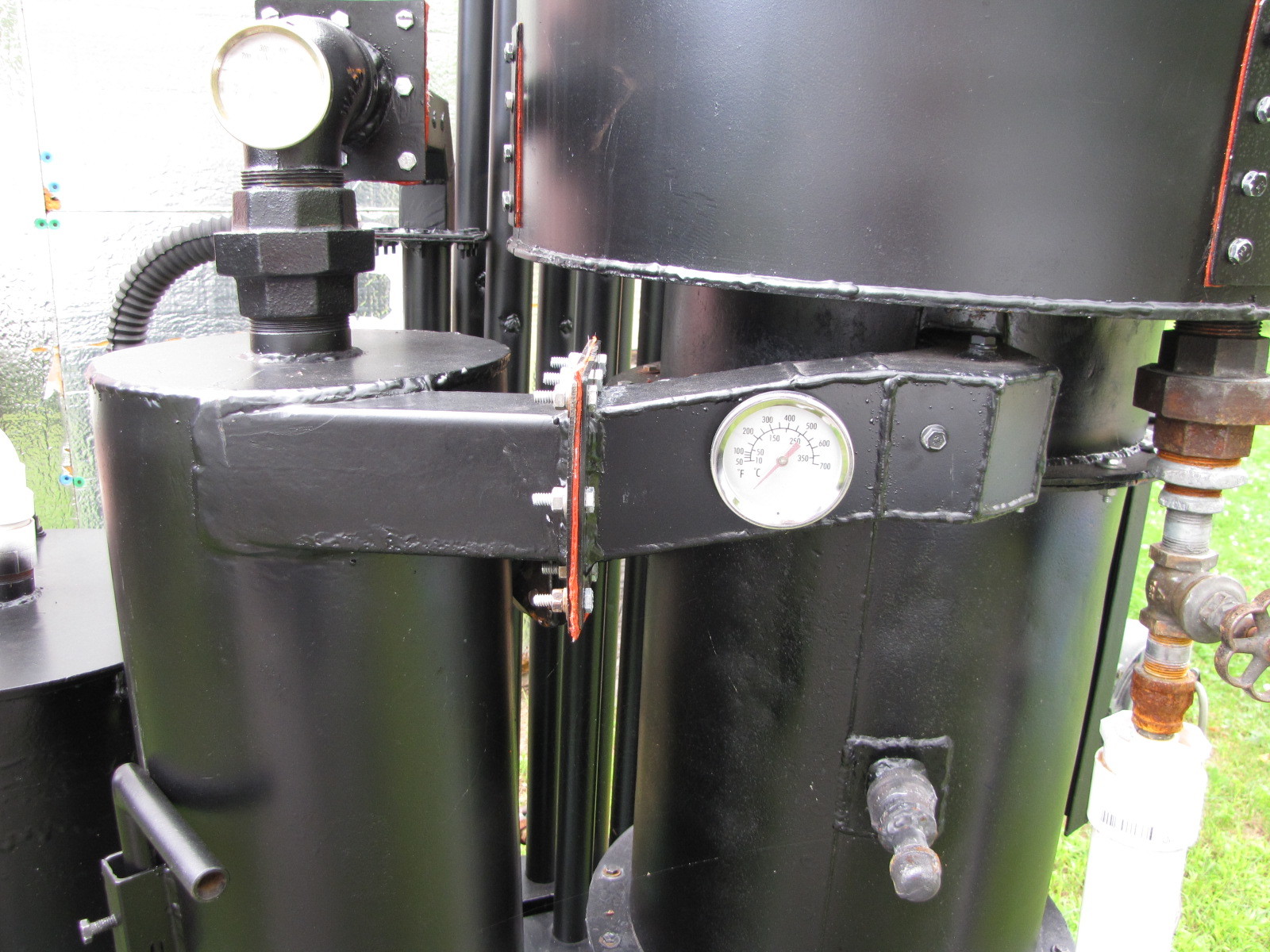
This one will tell me the temp of the preheated air entering the single port air inlet manifold. Probably should be insulated so these are about temps but good enough for trends.

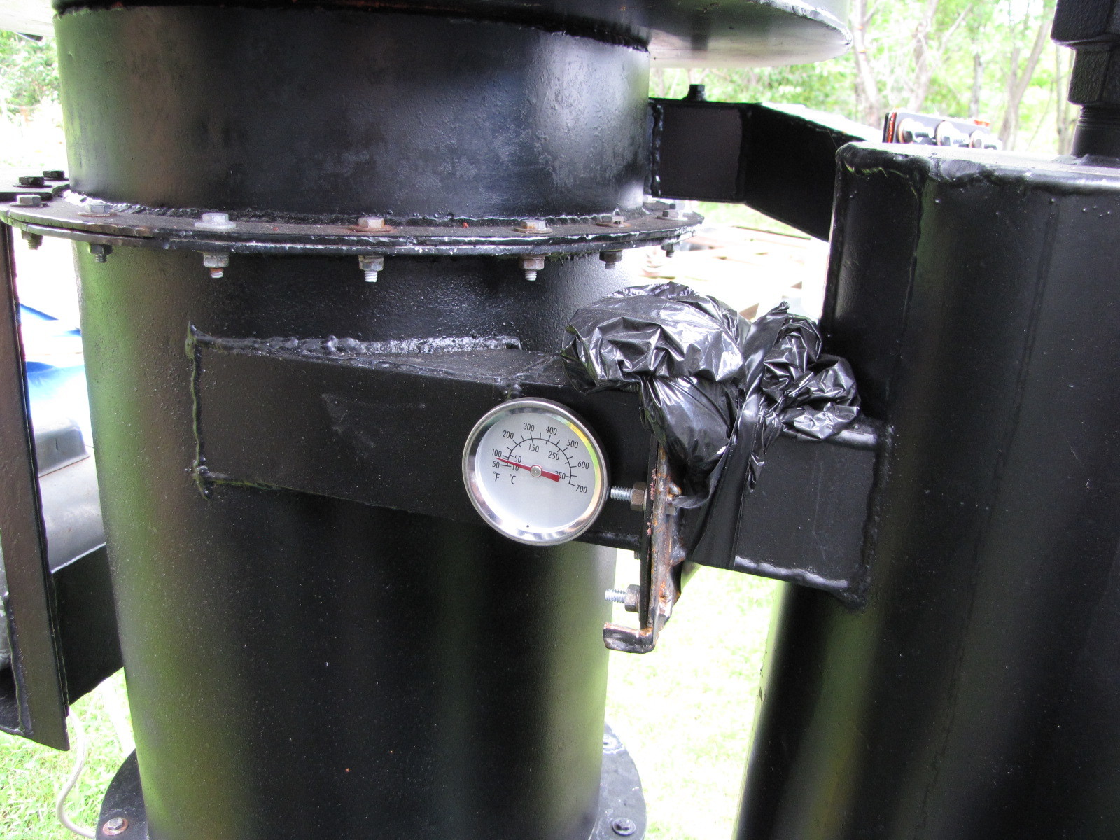
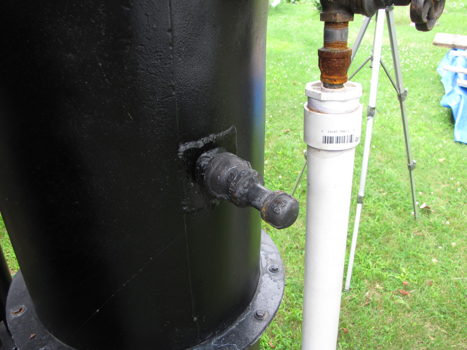
NEW. This is the temp of the hot gas exiting the burner shell and flowing into the side of the cyclone inside the preheat shroud. Again, could be insulated. The poly was used to cover the connection while the caulk cured. I should have removed it for the debut, lol.

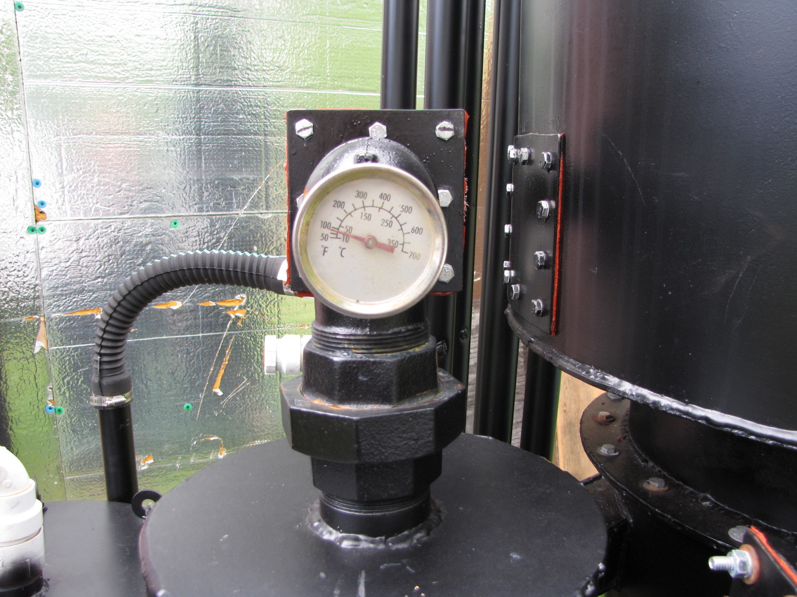
This is the temperature of the gas exiting the top of the cyclone and headed for the cooling tubes (radiator). This will give me sense of the temp drop through the cyclone. If this temp gets too low some condensation may occur in the cyclone.

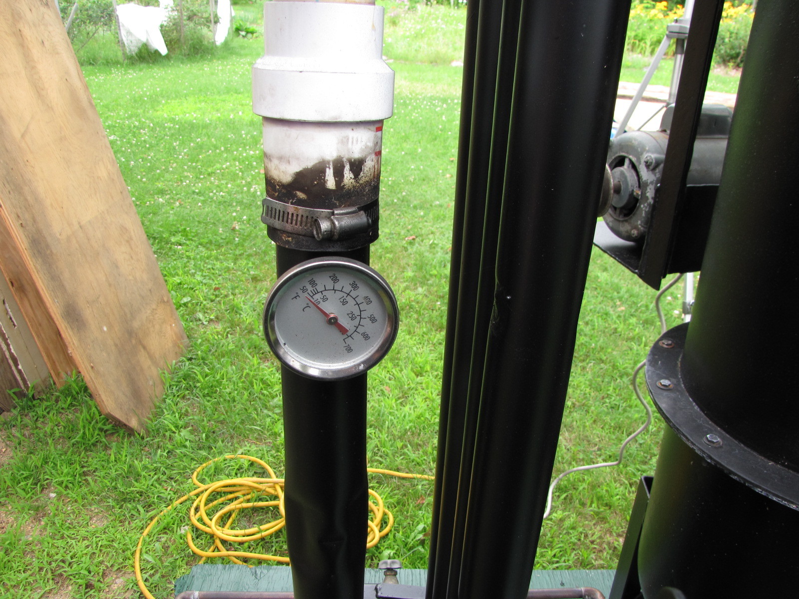
This shows the temp of the gas exiting the radiator and headed for the filter.

I can use the lighting port to insert a temp prob into the oxidation zone. This is the temp I am most interested in.
Yes, everything got a new coat of paint all the same shade and sheen, lol.

4 Likes

Hey Everyone,
I used to wrap the vacuum cleaner tube with duct tape to get an airtight fit, then wrestle with it a bit to switch from flare (no filter) mode to run mode with filter. Here’s a better and quicker connect/disconnect method. This is just a method, your sizes may vary. A flaring method will be incorporated into the final engine feed design.

Dig out a matched pair of those old vac wand pieces.

Cut a 3" piece off the receiving end (piece on left).

Epoxy the vac piece inside the 1 1/4" thin wall pvc pipe.

Glue the 1 1/2" coupling to the 1 1/2" stub on the exit side of the filter shutoff. Glue in the 1 1’2" x 1 1/4" reducing bushing and lastly glue in the 1 1/4" pvc pipe containing the vac piece.

Flare connection and shutoff. Fits like a glove, quick and easy and air tight. This valve didn’t need the 1 1/2" coupler.

Flare setup. Shut filter valve, open flare valve to direct gas to the swirl burner. I installed the “Y” upside down.

. When you are satisfied with the flare, switch to the run set up. ALWAYS shut off the vacuum first, then the flare valve. This will eliminate the point of ignition from the swirl burner. Pull hose from swirl burner and lay on ground. Quickly switch the hose from the flare outlet to the filter outlet and immediately open the filter valve and turn on the vacuum. MOST IMPORTANT: let the gas run for several minutes +/- to flush the oxygen from the filter unit and lines. Caution here, if in doubt let the gas go longer before using it. The filter could be a bomb.

Move vacuum closer so you can shut it off from the pallet. Do this first. Then shut off the flare valve, step down disconnect the swirl burner tube (notice the old duct tape sealing method) and step back up move vacuum line to filter and open the filter valve. If it takes you 10 secs, you’re too slow. Reconnect hose to swirl burner ( turn on fan) or engine, continue burn. If connecting to an engine you bypass the vacuum (it’s now provided by the engine).
The weather is supposed to be nice tomorrow, so I’m going to burn some measured amounts of wood, take some data and video and report back. My friend and neighbor, Bill, is coming over to watch the firing, it should be fun.
Pepe

3 Likes

Hmmmm I’ve always shut the vac off first then closed the valve… I found that that the vac would try to go into jet engine mode momentarily if done the other way.

1 Like

You’re right, Arvid, I plumb forgot, “fan off”! I’ll add it in, thanks.

Hey Everyone,
This is my new fan project. I like the motor/rotor separation, no mixing here, hopefully.
Gordon Ooghe, from post 275, I’ll have more info for you soon.

I rolled a cone to transition from 2" pipe to the 5 1/4" fan inlet. I used eighteen 20 degree bends. This type of inlet is one of those efficiency tweeks. It’s not totally to the spec 7 degree slope, it would be longer so I compromised a bit.

I caulked the outside and pop riveted it to the front cover from the inside for a minimum clearance fit.

Exterior view of fit.

I needed a T20 secure torx bit to remove the screws.

It has a 4 1/2" X 6 1/2" base for securing to the unit.

Ready to adapt to 1 1/2" piping

Does anyone here know if this motor can be speed controlled?

Thanks, Pepe

3 Likes

Hi All,
I had to make a clearance adjustment on the fan blades. I ran it and it dinged, so I made the adjustment. Runs fine now.

Pepe

1 Like

Hey All,
I used the end of a 4" pvc pipe cap to cut out a flange for a 2" pvc coupling at the fan exhaust port.

I’ll leave this til tomorrow am before I drill the mounting holes. I will drill graduated holes to eliminate cracking the flange by taking too big a bite. I hope this holds up to the test of time.
Pepe

Well, it’s tomorrow and here’s the finished fan ready to fit into the system. At this point in the beta version, it may be a stand alone unit. My bigger picture is a little more compact unified arrangement and I will fabricate a metal adapter for the outlet just to be safe from accidentally breaking the pvc… It’ll fill my winter hours in the shop.

I ended up splitting the housing and putting high temp grease on all the mating surfaces. I had some slight smoke leaks before I did this.

2 Likes

Pepe,

I have the same fan. I made a plasma cut “exit to 1.5"NPT” fitting if you need one made of metal.

Stephen

Hi Stephen,
Thanks for the comment. What I really need is a plasma cutter, slip roller, etc, etc, etc as Arvid said.
May I ask how you transitioned the intake? Any clearance issues like I had. The fan has relatively close tolerances.
Pepe

1 Like

Hi All,
I opened up the hopper this am after a nice evening burn and was surprised to find the bridge across the River Kwai.

I thought, “oh, no”! How far down did it just burn?

A closer look showed why the unit kept running like there was no bridge. The fuel you see in the firetube fell from underneath the bridge and the hearth was fed and continued a good gas producing burn as seen in the last seconds of the vid. I like the gas color. I estimate I would only have had another 20 or so minutes of run time before the fuel was 4" above the nozzles. Much, much longer had the bridge collapsed.

One tap from a stick and the whole bridge collapsed just as you see it. Odd, too in that I ran the vibrator several times during the run. It’s now ready to start over with a new char bed established. I’ll just top off the hopper . I think I will move/rearrange the vibrator mechanism more to the hopper side.

Ambient temperature 65 degrees.
Here are the operating times and temps throughout the burn. I hope they’re dark enough to read.

All in all it was a good burn. The temps were slow to peak which I attribute to the fan being under powered for my particular sizing of gasifier. It certainly works well though as a good starter fan. The scrapping racket you hear from the fan on startup happens when I push on the motor or switch housing. It moves the blade closer to the housing and the tops of the mounting rivets. Just be careful.
Here are a short and long version of some flare action
.
short http://youtu.be/BqnjOxSNEvI

long http://youtu.be/r9mjJT_83IA

Pepe

1 Like

Your system and fuels will for sure be different than our systems. But when I set up our vibratro timer is usually off for only 10 to 15 seconds this is with the very light cedar. The on time is very short just a few seconds. I always start out with a close timed interval, this causes a rich condition and then back of the off intervals until I have a satisfactory flare. The Vibrator is as close to the top of the hopper as possible and in our case is very effective and touchy it does not take much. We want the machine to do some bridging to get the results you just experience. We try to get the shaker to shake down just enough to keep the hearth flowing and hot.

1 Like

Hi Matt,
Thanks for the response. So your vibrator comes on approx every 15 secs for a couple of secs. This means you continuously run the vibrator thru the burn. Yes, our fuels have a lot to say about this. I haven’t timered mine yet, but I previously ran it manually 15 secs every 10-15 mins. I didn’t this time, only 2-3 at most for the hr+ run. Time to install that timer!
My vibrator will move, also.
Pepe

Yes if you time this your machine will for sure run linear. This is my experience anyways :smile:

2 Likes

Hi All,
I finally got the flanges and bracket cut out and welded onto my hopper.
I welded one flange to the hopper using the hopper weld seam as a thicker base, shortened the original hanging bracket and bolted it together. I ran some beads on the pulley weight to increase the shake power. This certainly does shake the hopper now.
Now for another burn and hopefully the entire load will be consumed.
Pepe

5 Likes

I burned approx 30 pounds of fuel last night in 2 hrs and 22 mins. I was looking for a temp spike or point where I could refuel with the existing fuel still approx 4 " above the nozzles. I was about a 1/2 hr late, burned down to the restriction again, but I think I can start to get closer with my next burn. It’s pretty boring just burning wood and probably just as boring watching it. It was, however, informative for me. I ended up vibrating every 15 mins for 15 secs and had no bridging problems. I also shook the grate every 20 to 30 mins.
The vid is long.

This is the log I kept. The only real spike in temp was the hopper temp and (I learned the next morning) that by that time the fire had probably burned too far down towards the restriction. I’m thinking with a weighed load that establishing a time to refuel will be easier than depending on temps which seem to mostly stabilize .
Pepe

4 Likes