My Personal Small Wooden Collider

Yes, one central nozzle directed vertically downwards. This solution was proposed at one time by the Soviet engineer Rybnikov. From your drawing it is clear that he was not the only one who came up with this idea.

With a flow rate of 44 cubic meters per hour, as indicated in the second row of Imbert’s table, I may not need forced cooling of the nozzle. But it will be regular mode for my sizes. In forced mode, I will try to achieve a stable performance of 90-100 cubic meters per hour. At the same time, I plan to heat the bunker and an external monorator that constantly removes moisture from the wood. Therefore, I am already very worried about the temperature regime. Of course, I can supply clean water from the cooler to the center nozzle to prevent overheating, but this can impair the reaction to get good gas at high flow rates.

In old books on wood gas generators, such a parameter was indicated as the load of the grate, measured in kilograms of firewood burned per hour, on an area of ​​1 square meter. If I don’t confuse anything.

An adjustable nozzle is a good idea, but I’ll try to do it in a different way. Many experiments are yet to come!

6 Likes

I would not worry too much, I believe with the moisture removal you’ll still have a sufficient amount in the wood and bunker to maintain stable temperatures.

3 Likes

Yes, the nozzle should hold up well, just use some thick material, Corten steel should work well i’ve heard.
I’ve also curious to find some (used) of them BIG sand-blasting nozzles, available in different, very hard materials, i looked at some 1inch, used to blasting shipping containers, would be very interesting to try.

3 Likes

Cody, those who tried to use a small wood gas generator for a large engine, or a turbocharger - they know very well what will happen to the wood gas generator … :wink:

I’m taking this step consciously for several reasons: 1. Reducing the size and weight of the wood gas generator, 2. Increasing the stability of operation from the smallest modes to the largest, etc.

6 Likes

The air supply is ready! And although there are a dozen little things to finish, it is already obvious that it is time for me to prepare fuel for the first launch.

Me also managed to prepare 2 sets of insulators for the electrostatic filter, and check the operability of the high-voltage converter for it. I also adjusted the dimensions of the filter in accordance with the dimensions of the resulting insulators. Details will be later on the Premium side.

11 Likes

Starting the automatic ignition system of the gasifier in manual mode. :wink:

It turns out that it is not so easy to light and maintain a flame in the pipe. Even at low speeds, the turbine gives too much air. I had to drill a standard gas supply jet, which I removed along with the tap from the old gas stove. And still the ignition has to be kept constantly on, otherwise the flame is blown out of the pipe. Very interesting experiments, I really liked to collect from various cubes (what women usually call “junk”) a brand new device, and at the same time it works!

The spark source is a high—voltage converter for an electrofilter. Only transistor control will be done from a microcontroller and with normal drivers for the gates. Otherwise, gate resistors and a choke to protect transistors from through currents consume and emit almost as much energy as the converter itself in the form of heat.

10 Likes

Own personal fuel also causes a wide smile. The feeling of being cooler than an oil tycoon! Lemons are urgently needed! :slight_smile:

20 Likes

So, here are the results of 2 days of continued work:
Central lance, throat and grate cooling pipes, separating disc:

Air-cooled grate. View under the separating disc:

Sealing with aluminum foil:

Additional compaction with clay and sand:

Fuel readiness of the reactor:

The top cover was only with an aluminum seal, and it let the smoke through. Reactor without top cover:

General view of the experimental setup. The turbine is visible, the voltage regulator for it, the outlet pipe with the spark plug of the outlet gas:

Behind the reactor was a propane cylinder for ignition and an electric ignition system for 2 spark plugs at once (outlet wood gas and propane during ignition).

The results of the first run:

Hardened resin on the top cover. Feels like an excellent protective coating! So smooth and strong. :slight_smile:


Resin leaks from under the seal of the top cover:

The first charcoal and dried and smoked firewood:

Neck and outlet without resin:


Well, the main result of today’s launch! Now I am the real owner and user of the wood gas generator! :slight_smile:

The gas eventually caught fire, as it should, with a red flame, not only in the outlet pipe, but also from under the top cover! And there I have valves for adjusting the degree of cooling of the grate and neck, a propane valve with a plastic handle and a rubber hose, a silicone corrugated air supply pipe from the turbine. In general, a uniform fire - I had no time for video filming. Ran around the reactor like a joyful madman who doesn’t know how to stop the flame and the reaction of getting combustible gas!

8 Likes

Hello MaratL.
Your removed fuel wood “billets” shows many operational teaching lessons for using wood-for-power. Along with the deposits and tars drips pictured shown.

I had to go back up to your starting topic post and remind myself of your 7 purposes of this project.
So not just to as directly, and simply as possible, fueling an IC engine for working.
Please. Please. I do not criticize you. This is your project. Your works. Your approaches.

However for any use; the story of your removed devolving fuel wood chunks, tell is that IF a person pre-loads, pre-made wood charcoal at and above the air-in nozzle(s) then that wood charcoal will make clean converting process-heat much faster.
Jump starting the whole process.
You will then have the hot glowing very active carbons in that charcoal; hungry to eat-convert as much as is possible the upper wood volatiles being rising heat released.

Much less system buildup contaminations. Much less needs for elaborate downstream processing.

Lessons to me from my whole house heating wood stoves taught to me 1994-2002. Working to achieve complete smokeless burning. To be discreet in a place and time wood stove users were being more and more vilified as “tree-killers”, “planet polluters”, “unthinking carbons emitting greedy, selfish bastards”.
Ha! Ha! What you cannot see, you cannot be so bothered about.
I’ve never had to clean a chimney system since ~2000.
Use 50% less wood for the same heating needs.

Applied the same-same lessons later to woodgasifier systems operating. Any design. Any time. The only differences to me how long a particular system could be operated stable until needed full internal cleaning up (or burnout repairs) for continued use.
Regards
Steve Unruh

7 Likes

Hello Steve!

I make my gasifier so slowly that I also had to look at the beginning of this thread to remember the tasks that I would like to solve this device. :slight_smile: Almost 2 years have passed from the first welding seams to the first smoke! But this is only the initial stage of any wood gas generator… The most important thing is yet to come!

This is due both to the limited resources available to me, and to the many projects I started at the same time. All this requires, in addition to time and money, an investment of mental strength, which is returned only after the completion of the work begun. But life can end at any moment, and I would like my children and grandchildren to see the widest possible variety of tasks for which it is not a pity to spend a human life. And the beginning, as you know, is the most difficult stage in many cases, because it requires not only the initial idea and plan, but also determination!

I did not put charcoal in the grates and the neck of the wood gas generator because:

  • I do not have it, I did not plan to produce it, and it is unlikely that children and grandchildren will want to do this;

  • I would like to determine the total time required to start the reaction, under the most difficult conditions for the possible operation of a wood gas generator: for some reason everything burned to the ground, and there were only branches around, and only a saw on a tree in my hands. :wink: In particular, it is necessary to determine the volume of the cylinder for the starting gas, as well as the timeout for the safety of the automatic ignition system;

  • my next wood gas generator involves auger supply of fuel to the reaction zone, and perhaps the auger will not be able to deliver whole and unharmed pieces of charcoal to the grate, and only dust will remain from them, which the turbine will immediately blow during ignition. In order to discreetly place the wood gas generator under the car, the firewood bin can be located quite far from the reaction zone, which, moreover, will be in thermal insulation that does not provide for any service hatches (dust and small pieces of coal, according to the preliminary plan, will be blown into the electric filter, where will be periodically ejected automatically);

  • according to my plan, an electrostatic precipitator will immediately be behind the wood gas generator, and a gas cooler will be behind it, there will be a gas bypass in front of the electrostatic precipitator until the gas reaches a sufficient temperature (about 200 degrees Celsius) to prevent condensation of sticky dirt on the walls filter.

Idiots in our area amuse themselves in a different way … They do not attack those who have smoke coming out of the chimney, or those who clear overgrown abandoned forest belts from branches and old trees. Instead, they turn off the straw choppers on their grain harvesters to save diesel fuel, and they simply set fire to the straw swaths that interfere with their tillage in their fields!

Already several times there was a huge fire around our village, and this is the second time when the fire jumped over to our site with the help of the wind. We managed to keep the fire out of our house. He walked from two sides of the house. The firefighters who arrived half an hour later called it a real Miracle! Of course, this is a Miracle when you run with water in your hands and mentally ask your parents to ask God to protect your family from sorrow.

More than half of our site burned out, including trees that grew and grew with God’s help where I would like to plant them, but they could not take root in any way.

This is a view of this half of the plot with an unfinished 600 m3 stake. water (one of the started projects…). Behind me is a surviving vegetable garden, a whole house and an undamaged barn. It’s good that there was enough water in the well, in the containers for watering vegetables in the garden, and even water from the septic tank, which saved the rural wooden electric poles from the fire. Pond for 600 cubic meters. and a motor pump would not hurt this time!

Neighbors have less damage from fire, but they were on the street during the arsoning of straw and began preparing to extinguish the fire earlier … They also managed to come to our aid when they protected their site from fire.

15 Likes

You have had way more than your share of lessons Marat. Hard to accept, but it has tempered your spirit. Trial by fire. The world is in transition. The weak and dependent will not likely survive or they will learn your hard lessons very quickly. The old world order is dying and they realize it. In their death throes they do not care how much they destroy. The lesson for all of us is that no one is immune from this chaos and a stretch of time lays ahead where we will have to fall back on our own devises. What we teach each other here could be the difference between life and death.

13 Likes

Parts for the most intriguing part of this project - the electrostatic precipitator! :wink:

If betting shops evaluated wood burning gasifier projects, what would be the bets on this electrostatic precipitator? :slight_smile:

I wonder if I will be able to hermetically weld these 0.55mm thick galvanized sheets with MAG welding or will I have to assemble everything with sealant and rivets?

And this is an old flow meter from some ancient Toyota. I hope it is still in good condition, and then I will have to compile a table of correspondence between the flow rate of gas passing through it and the voltage at the output of its internal damper turn sensor. And before that, make transitions from his 80mm pipes to 50mm pipes in my system.

6 Likes

Lep pozdrav Marat, pocinkano pločevino se da enostavno spajkati z mehkim spajkom, spoj mora biti prekrivajoč, no, pred spajkanjem lahko spoj stabilizirate z nekaj zakovicami. Z elektro filtri nimam izkušenj, uporabljam le seno, žagovino in ovčjo volno, ki dobro očisti plin, lovi pepel in premogov prah, uplinjevalnik pa poskrbi za katran. Dobro se je učiti od drugih, dobro je tudi preizkusiti lastne ideje, vendar se moramo zavedati, da dober uplinjevalnik nadomesti rezervoar za bencin in je glavni element, vse ostalo je pomožna oprema.

2 Likes

.55mm is about the thickness of pole barn metal roofing. I don’t think I could get a air tight weld with that. Especially galvanized.

4 Likes

Hello Tone!

This topic is a place of practice for working out solutions on my topic “Gas generator of the future”. There will also be a topic on the Premium side in which all the positive results obtained here will be collected in the topic “Mini CHP, wood-fired, 11 kWh”. With drawings and dimensions, detailed descriptions, specifications of elements, program texts, etc.

Now the main task for me is to reach the production of 100 cubic meters of gas per hour, with the size of the reactor zone designed for 44 cubic meters of gas per hour (second line of the Imbert table). This task alone is completely insane! After all, everything should melt and burn to hell… But I will still try not only to prevent this, but also to make it a completely normal operating mode for such a compact reactor area.

I can’t measure hot and dirty flammable gas. I have nothing to measure this with. And without measuring gas consumption, I just warm the crows, and even in the summer! But I have a flow meter (pictured above) that should cope with measuring the flow of clean and cooled gas. And since I am very limited in resources, so I cannot make several filters and coolers for experiments. Therefore, I now need an electric precipitator and a gas cooler, which will be of this size:

If my calculations are confirmed in practice, then an electric precipitator capable of cleaning 100 cubic meters per hour will be the size of this 20 liter canister. At the same time, it will self-clean, condensate will never freeze in it, and its mass will be approximately equal to three masses of such empty canisters (judging by the total mass of the planned materials of which it will consist).

This same radiator for antifreeze will be the gas cooler. And it may well turn out that its cooling capacity will also be excessive - gas will flow to it after heating the firewood in the bunker with clean gas. Ask yourself: would you like to have the same gas filtration and cooling system for a 100 hp engine?

Thus, at this stage of work, the gas generator is only a smoke producer for the main work on the manufacture of instruments for measuring and monitoring reaction parameters.

My plans for the first launch of the gas generator were to determine whether the resulting smoke would be humid enough so that the condensate obtained from the firewood would be enough to maintain the planned parameters of the reactor. It turned out that there would be more than enough water. And this is good!

It would be nice to come up with a simple way to separate the resin from the water, and return the resin back to the bunker, it should burn very well.

Of course, I had great pleasure, for the first time in my life, dividing the fire into two components: the smoke in an iron barrel called a “wood gas generator” separately, and the fire from the smoke in a completely different place! Almost like Bruce Almighty, who separated the borscht:

3 Likes

Marat, if we are talking about the construction of a hot zone for 10 kW of power, it is very important that you have in mind the size of the wooden pieces, so that they reduce nicely and create a charcoal bed for gas conversion. 10 kW is not whooping cough, this is concrete power and according to the pictures of your fuel, I would say that the diameter of the hot zone should be at least 20 cm.
I am planning to make a gasifier with one diameter from top to bottom, where bridging (sticking) of fuel will not be possible, this is especially important for stationary units (there are sketches somewhere in the next topic). 10 kW of power means consumption of at least 10 kg of wood per hour, i.e. a volume of approx. 30 liters. You are talking about the separation of water vapor from tar gas, … theoretically, water vapor is the lightest gas that is released from the wood and remains under the cover, so I think that a properly cooled cover with a slope for draining water, almost optimally eliminates excess water, tar and the gas is returned to the process. :thinking:

5 Likes

Tone, I’ll start by answering the easiest question. About removing moisture. The hopper is hot, water and resin are in the form of steam. The lid must be cold so that the water can condence and flow into the chute for disposal outside the hopper. Not only does resin condense on the lid in addition to water, but cooling this lid is not easy if it is hidden somewhere under the body of the car, or in a niche in the trunk, or somewhere else. But the resin may not want to all drain away along with the water, and then the lid, sooner or later, will inevitably have to be cleaned. What’s also bad about this lid is that moisture and resin condense, but along with them, hot gas touches the cold lid, which is not able to condense at this temperature of the lid. For example, hydrogen, CO, CO2 and methane will generally refuse to condense in such unsuitable conditions! But the heat, many, many BTUs they will bring with them and transfer to this lid. In order to lower its temperature, with such increased heating, for the successful condensation of water, and the same resin (which we would like not to accumulate there, on the lid!), we will have to release these BTUs into the atmosphere to heat the crows…
Wisdom from the mouth of Steve Unruh tells us: “Let NO BTUs Escape, Free, Unchained, Unused!”

I still can’t imagine how to take heat away from this lid in order to return it to the reaction, and even in cramped space with a hidden placement of a wood gas generator.

Therefore, my monorator will be external, the bunker will be thermally insulated, including the loading hatches, and the flow of smoke will be forcibly drawn in by an auger from the bottom of the bunker and drained out into the upper part of the bunker. The outer surface of the monorator pipe will be blown with cold air from the turbine and, after heating, supplied for further heating to the hotter zones of the reactor.

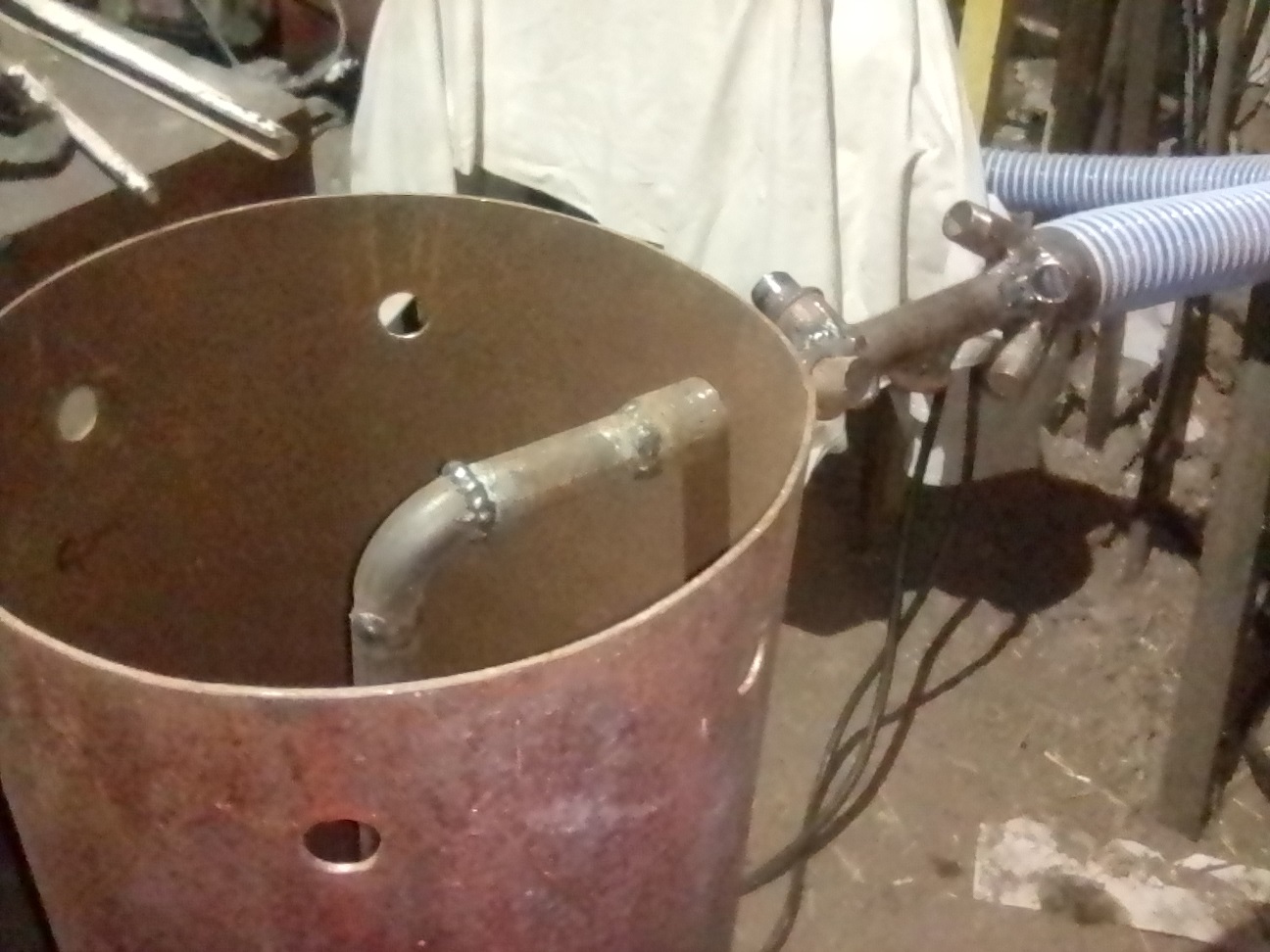
Now about the sizes of wood gas generators. They are usually tied to specific wood gasifier designs. I selected the approximate dimensions for this gasifier from the maximum firewood consumption of 21 kg per hour. Again Imbert’s table. And even here I couldn’t resist and, instead of the recommended tuyere belt, I chose a central nozzle, like Rybnikov’s. I did this so that my first gasifier could immediately produce combustible gas. At least within the limits of consumption as in the 2nd line of the Imbert table for these reactor sizes: minimum gas flow rate is 5 cubic meters per hour, maximum gas flow rate is 44 cubic meters per hour. And there are plans to make it convert 50 kg of firewood per hour! And remain safe and sound.

Just to have a working gasifier right away, here and now. To have something to heat tea or coffee with, in order to calmly survive possible errors with the “gasifier of the future.” Which, by the way, does not have a throat at all, and the only calculated parameter is the size of the wood pieces no more than 5cm5cm5cm. Only so that they can be pushed by a screw in a pipe with a diameter of no more than 15 cm!

Everything else is planned not on the basis of someone’s size and design, but on the basis of the needs of the gasification reaction itself. “Get your zones temperatures UP; and kept UP - and the chemical changes will take care of themselves.”

The temperature of the coal bed must be high enough to decompose tars and carbon dioxide, but not too high so as to destroy the gasifier. “Take care of the char bed and the char bed will take care of you.”

The fuel feed must correspond to the gas consumption, and not to how many kilograms of firewood could fall into the air blast zone. Those. fuel must be supplied deliberately, as in injection cars.

The narrowing zone in the neck is needed, as far as I could understand, primarily to increase the temperature and sufficient density so that reactions take place with all the smokes components passing through this zone. Moreover, the density here should be high enough so that none of the molecules leave deprived of high temperature, and at the same time, the density of this zone should not be too high so as not to create a plug for passing gases. Those, this parameter also needs to be adjusted. And gas consumption is also a very important parameter here. The density of this zone will be maintained by a brainy algorithm for controlling the auger feeding wood pieces.

In any case, that’s the plan. How it will actually be, what difficulties will still have to be faced, what solutions will be found - all this is still to come!

The main idea is to replace the geometric dimensions of gasifiers of various capacities with several software and hardware regulators of various parameters in separate zones of the reactor, and to derive the necessary patterns for stable operation in different modes.

People solved absolutely the same problem when a gasoline carburetor, which was highly dependent on air flow, was replaced with tables for fuel supply and spark formation in injection systems. The process has become very stable, the problems of inconsistency in transition regimes have disappeared forever. And reliability has increased due to self-diagnosis of sensors and actuators. To do this using mechanics alone is a very difficult task.

I really enjoy discussing these ideas. Every time there are some additions to the already invented solutions. For example, the original idea of igniting a gasifier using pre-pumped gas into a cylinder will not only cope with the transient conditions of the gasifier, but even maintain its full functionality with zero gas consumption! Those, it will be able to operate steadily from 0% to 100% of its output without losing its temperature and coal.

Here is a rough sketch of what I talk about so much (and there is already something to add):

11 kWh of electrical energy - this will be the nominal mode. The maximum mode will be 22 kWh of electricity. Moreover, for an electric generator this will be its rated power. Thus, we will have a constant 2-fold power reserve without compromising the insulation of the windings and other parts of the generator.

Why then the gas consumption of 100 cubic meters per hour? The mini-CHP will produce heat, electricity, and purified gas for external consumers under an excess pressure of, say, 0.1 bar. For gas heating boiler, for gas cooker, for gas water heater, etc. Maybe for an old gas lamp? :wink:

5 Likes

Marat, if we go down into the core of the gasifier, i.e. the hot zone with coal, where the temperatures in the middle are well over 1000°C and the entering air is preheated to 600-700°C, we can imagine that the gases in the middle are forced upwards and overheat and gasify wood in the middle, so this intense temperature is reduced, but still there is a column of hot gases in the middle that reaches the lid. What can we do here? We are trying to adapt the interior of the gasifier to these laws, the WK gasifier is a good example, so far I have not seen a better design, even my concept is a “copy” of the WK with some changes. The upper part is colder and the fuller the hopper is with wood, the more mainly water is secreted, the warmer this part is and with less wood, tar is also secreted,…

10 Likes

8 months have not been in vain… We are collecting our UAZ Husbandman!

Fitting the engine mounts to the frame.


It is already possible to ride on a 4-wheeled scooter. :slight_smile:


While we were thinking about how to bring the old cabin from the car disassembly, someone managed to cut the roof off it there. Now we have a convertible, but almost for free. You can still try on all the main units using the factory cabin. Then we’ll change it when we need a roof. Or fix a beach umbrella from the rain and sun. :slight_smile:

The real breakthroughs for the continuation of work on our UAZ Husbandman first occurred when a good person gave us a bunch of spare parts from other cars:


Individual ignition coils with integrated switch. From Toyota Land Cruiser V8. 4 pieces are still in stock.


Valve, gas pressure and temperature sensor and propane nozzles.


One of the two electronic chokes. This one in particular is from Mitsubishi Pajero. The other one is from the same Toyota.


Crankshaft sensors from ZAZ Tavria and from Toyota Soarer.


is a homemade electronic engine control unit for Arduino Mega. There will also be transmission and hydraulic control units connected to the engine block.

The second strong jerk occurred when we made a folding cabin on our UAZ. It cannot lean forward, because there will be a front hydraulic suspension, as on tractors. You can’t go back, because there will be a dump truck body. It is also impossible to tilt the cab to the driver’s side, because there will be a woodgas generator under the cab.


It remains only on the passenger’s side, because there is only a propane tank. Which is already fixed to the frame.


The electric motor of the dry sump system and 2 pumps from hydraulic amplifiers will be mounted in front. Behind it are 2 cans of 20 liters each: with oil for the engine lubrication system, and hydraulic oil. Individual ignition coils are already installed on the engine. There will be no more Trambler. Mechanical power will be taken from the front edge of the motor to drive a gear hydraulic pump (125 l/min, 150 bar), an air conditioner compressor and a 12V electric generator, an air compressor (200 l/min, up to 10 bar) and a 3-phase 220/380V electric generator with a capacity of 3KW and 3000-3600rpm.
Also, an air filter and an electric turbine for pressurizing air into the engine and into the wood gas generator will be fixed above the clutch housing. The climate control unit with a cabin filter, a fan, a recirculation valve for cabin air, an air conditioner evaporator and a heater radiator will be located above two oil cans. And only the air through the pipes will enter the cabin.


Ignition coils and numerous hole`s plugs on the engine are clearly visible. There will never again be a mechanical cooling pump with its current oil seal, there will be no old thermostat from which it is impossible to even request its current position or the number of trips before its complete failure. A liquid flow sensor will also be installed at the outlet of the cylinder head. And in case of its absence, the engine will be turned off before it overheats. Because we need reliable equipment for timely farming, because “One day of spring feeds the whole year!”


The DriveOnWood forum is the place on the Internet where you do not need to explain why two throttles are installed at once at the intake to the engine! :slight_smile:

20 Likes

That’s pretty exciting Marat. Goes to show what can be done even in very hard times by a person with the will to work. I had to look up Trambler. Never heard that term before. Some kind of Soviet era ignition distributor it seems.

11 Likes