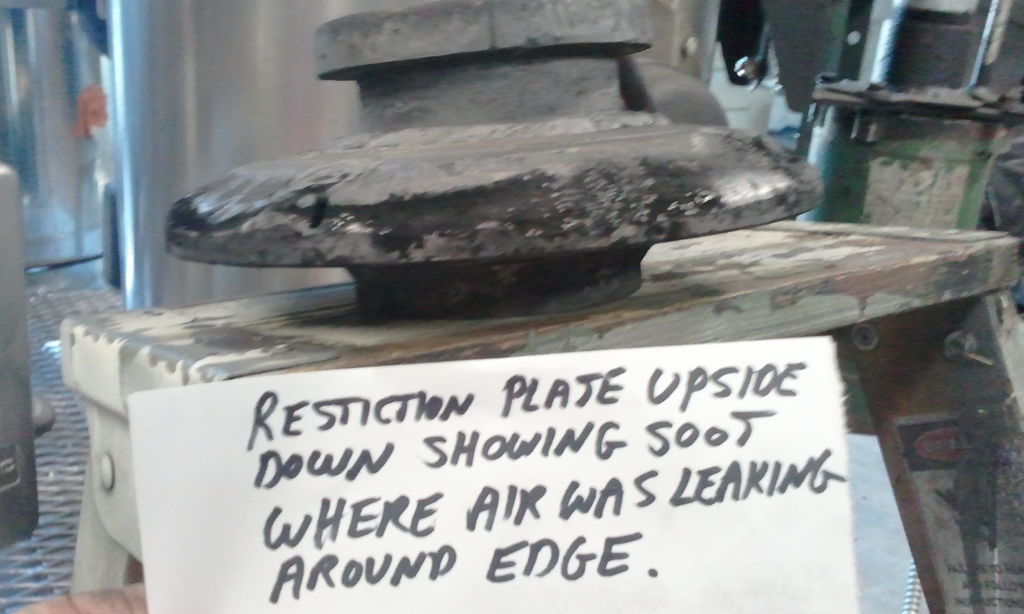
This is a picture after a clean out down below my nozzles. It appears blacker around the edge of restriction plate than in the restriction opening; leading me to believe air leakage around the plate that i did not seal.This is what Richard suggested.What does everyone think?

Hi Danny, I thought I’d chime in with a suggestion, if you suspect that’s where the leak is. This may not be permanent but if it has a positive effect on your gas color and quality then you have your answer. I would gently lay/stuff some small diam fiberglass rope around that dark circumference and then cover it with refractory cement much like chinking a log. Like I said, you’ll at least be able to test the effect on the flare to help isolate the problem. I spent a year building a FEMA and a fluidyne(I’m going to make this work if it drives me nuts!) with mixed results before I decided to take someone’s well meant advice to start building an imbert to the numbers. I drew up and
built what I posted here, I cut up and used the fluidyne parts to do it and I’m happy with the results of my gek type gasifier.
I’m real curious about that dark area now.
Good luck if you decide to try it.
Pepe
PS: Something else I wondered was how wide a grate you have and how deep a pile of glowing hot char does it hold. This could affect residence time of the gas flowing through the char bed. Longer time is more reactions complete, a higher percent of burnable gas in the stream as a whole. I know it sounds strange as fast as the gas is flowing, it did to me at first. Think 6.02 X 10 to the 23rd power reactions in micro seconds to put residence time and distance in perspective. The imbert dimensions are designed to optimize this performance.
You confessed to being long winded. I think you have some competition. lol.
Competition welcomed along with the advice.I now have my gasser apart.New filter built,testing port for reduction area in progress,larger air mixing holes in flare stack.I think i am close to where i want to be in regards to 3" restriction, so i welded thick s.s. restriction plate in place.No more leaks and if i decide i need 3.5"-4", i’ll just blow it out with plasma torch.there was definate leakage around plate,will attempt to post pics.My bowl/grate design is a hybrid 12" Dia. 3" char layer below bottom of reactor bell.My design is such thst the gas can’t miss going thru a very good char zone.Sorry,can’t tell you which video on youtube shows bowl design, somewhere between 1 and 5(docdcox)Can’t wait to get it done and reassembled to see if it worked.Thank you so much for caring enough to help me. Dan
Pic1- upsidedown restriction plate showing soot/air leakage around edge.
pic2- fuel removed 3 nozz. out.
pic3- fuel ay nozzle level, dots on nozzles.

Hi Dan,
You’re welcome. I think the over whelming attitude on the site is that everyone wants to see everyone else succeed and to help where they can to make it happen. Such a positive team oriented atmosphere. Pics are good to see what you mean. It’s ground pretty smooth, too. Deceiving it didn’t seal, isn’t it?. I’m glad you found something to confirm suspicion. I’m as anxious as you almost to see the results.BBB.
Regards, Pepe
Hey DannyC
Pepe is correct most of us will do anything to help a fellow get up and running. My forte is to be able to make anything produce usable fuel gas for at least a percentage of time. Then a fellow can get on with the actual de-ashing, cooling, condensing, filtering and IC engine running - the 75% of it past the actual reactor hearth fun.
Nice picture set, shows the problem alright.
So concur you were getting bypassing. You could have sealed with slitted stove rope outer wrapper glued on the restriction plate and the outer housing wall and then just “corked” into place. Welding will seal it - but this plate as the second hottest part in the system now “solid” with no expansion wiggle DO watch for cracking next to your welds after a few firings.
Imbert variants are OK and have good maths now to follow. As relatively small volume air nozzle to restiction capacity systems they are very narrow range of turn down (minimum good gas flow to maximum good gas flow) systems. 3 to 1 typical with even the best insulated at only maybe 10 to 1.
Do read and look at the pictures on Dutch Johns MicroGasifers link up in the Resources -> Links.
Look at his side bar picture pencil diagram. Note the suspended fuel flowing cone above the nozzles from his hopper lower to just above the nozzle tips. If you add this you will keep pyrolis gases and tars from bypassing behind the nozzles. You do want this to be open on the backside at the bottom to allow rising char bed heat to heat this cone liquifying the dripping down tars making then flow right in front of the nozzle openings to be oxidize converted.
DJ is not the only one now using this feature. The others are proprietary designers I cannot name.
Regards
Steve Unruh
Richard and Steve; We will find out soon how i did.Will watch for cracks around plate and i’ll check out Dutch Johns link.Take care.Dan
P.S. What does BBB mean and i hope this isn’t s duh moment?
Burn Baby Burn
BBB Duh! Thanks Arvid
Hi Dan,
I drew a blank when I first saw it, too. Thought I’d confuse somebody else. I learned on my last 3 successful burns there are improvements needed yet. My cooler is not a good configuration (it’s a “what I had” model 1 copper S). I need to go up one side,down the other vertical tubing, condensate drain and clean out ports. This will give me a lot more cooling area in the same footprint. My milk can filter works OK, but I’m headed towards a box type dual compartment, possibly a condensate drain area here also.I had a fan that was sufficient but it failed mechanically, so I’ve been using the vac to start up. Noticed water in the vac after the run. Hmmmm? I’ll be building a new bigger fan also. I’m hoping to use a 12 volt generator from my old Scout to run the fan (also speed controllable). So that’s my winter work shop schedule.
Good luck, Pepe