I like this auto mixer it says simple too build.Nice work Koen man.
So, this one is:
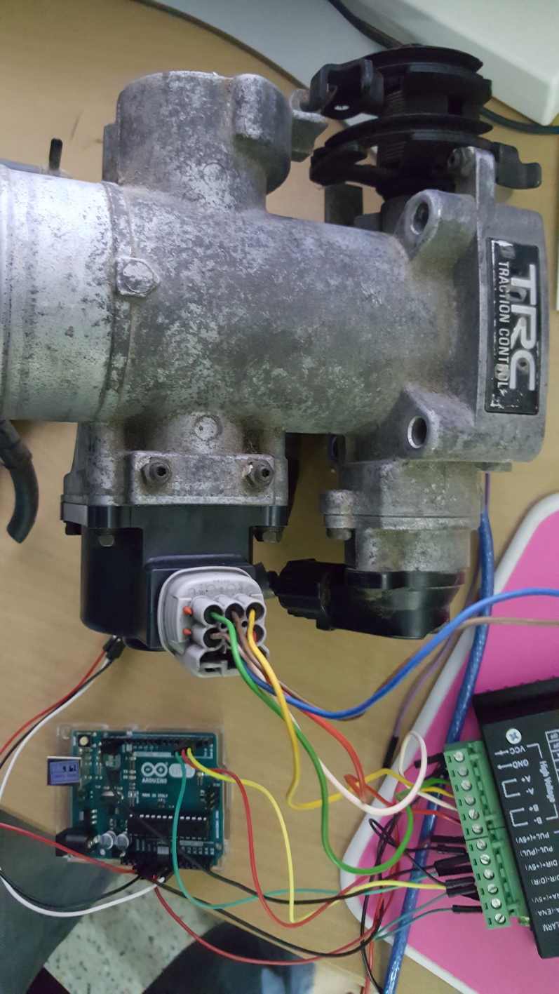
Throttle body / stepper controlled by arduino.
I will try to keep things in one posting or i should create another topic per different build…
The video:

The hardware:
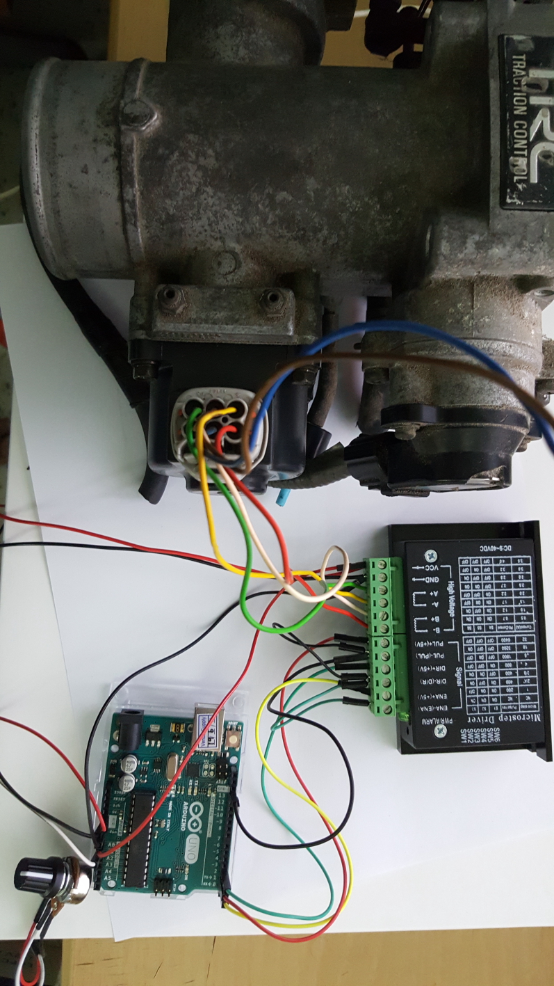
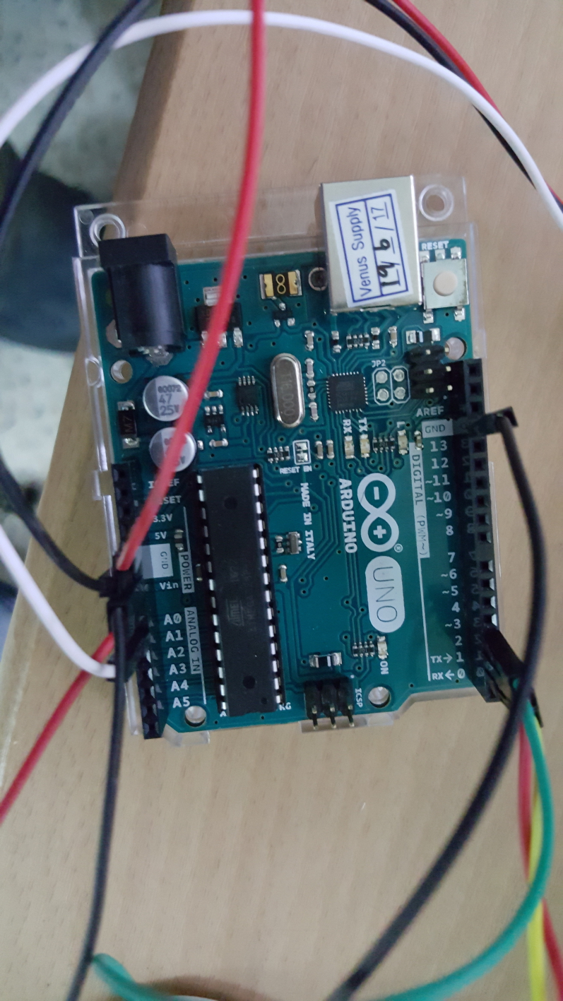
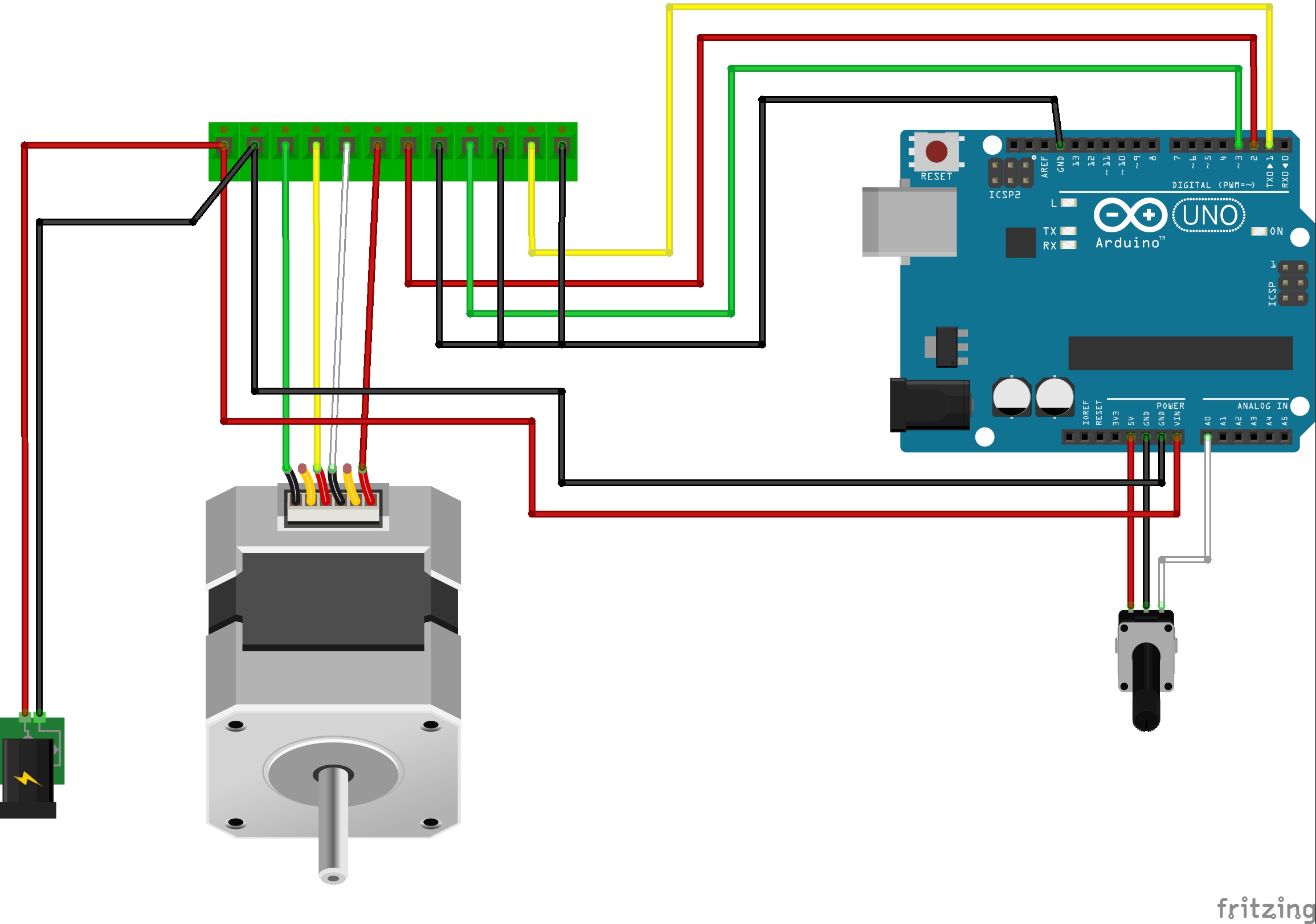
The sketch / wiring:
The Arduino code/program used:
#include <AccelStepper.h>
// AccelStepper Setup
AccelStepper stepper(1, 2, 3);
// Variables to store current, previous and move position
int val = 0;
int previous = 0;
int long newval = 0;
void setup() {
stepper.setMaxSpeed(19200); // Set speed fast enough to follow pot rotation
stepper.setAcceleration(19200); // High Acceleration to follow pot rotation
}
void loop() {
val = analogRead(A0); // Read Potentiometer current value
if ((val > previous+10) || (val < previous-10)) { // Check that a move of the pot is at least > or < than 10
newval = map(val, 0, 1023, 0, 3000); // Map value (3000 = 2/3 stepper shaft rotation)
stepper.runToNewPosition(newval); // Move stepper to new position
previous = val; // save current value into variable previous
} }
Digital out 1 / yellow cable = enable pin
Digital out 2 / red cable = Step / puls pin
Digital out 3 / green cable = Direction pin
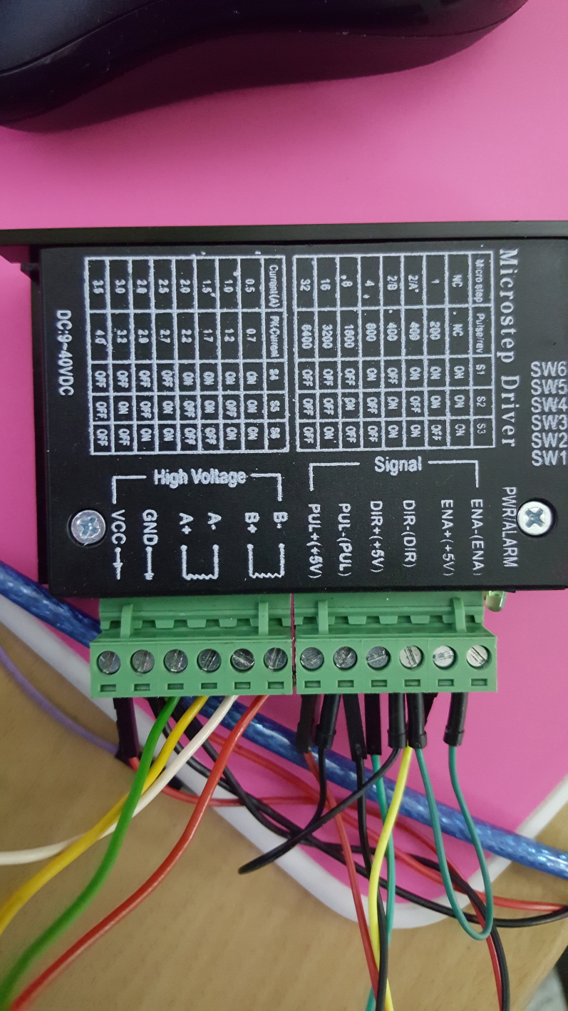
Stepper driver from internet:
http://www.lazada.co.th/hengjiaan-4a-stepper-motor-driver-controller-board-black-green-intl-17367482.html?spm=a2o4l.search.0.0.448J8V&ff=1
Download link for the AccelStepper library:
http://www.airspayce.com/mikem/arduino/AccelStepper/
Download links for the Fritzing program ( for free ):
http://fritzing.org/download/
The Fritzer files from the setup i can send per PM
If questions, ask…
5 Likes
Hi Koen is there a universal steper motor or say one too fit a s10 v6 or 4 cyl. Throtle body or would this thotlebody be pre factory location inline before the one on the origanal efi.Just jumping ahead a little.?
Maybe I’m old fashioned, (not maybe, just really) but for me a cable is so much simpler. 
5 Likes
I agree about a cable being simpler and reliable but
The 75% learning and attention to the AFR meter and one hand on the air valve is needed if you are in stop and go traffic.
I am not afraid of taking on just about any mechanical issue, but electronics still seem like magic
Koen I am so impressed with your knowledge and craftsmanship (and your operator partner)!
Electronic is the way too go fore more space under the hood. As easy as can be and we will get it after a whiles studying, Caint wait too get the siml’est version learned for starters, a section at a time, would be more readable too me , Thanks plus 30 charictors. I know your just getting started so i will stop talking and let you get back too idea sensencing programming stuff.I wish i would have taken electronic college instead of auto mechanics.usefull class insted of muffler repair change oil class when i had free schooling chance nafta.
That is where I am coming from too!
2 Likes
Electronics can get over my head in a hurry but I do understand a push/pull cable 
5 Likes
It’s over my head too, but I am sure Koen has plans to run this stepper motor with a signal from an O2 sensor for an auto mixer.
1 Like
Hi Kevin,
Any throttle body can be retrofitted with a suitable stepper motor ( size depends the spring inside the throttle)
But the electronic as shown will work to
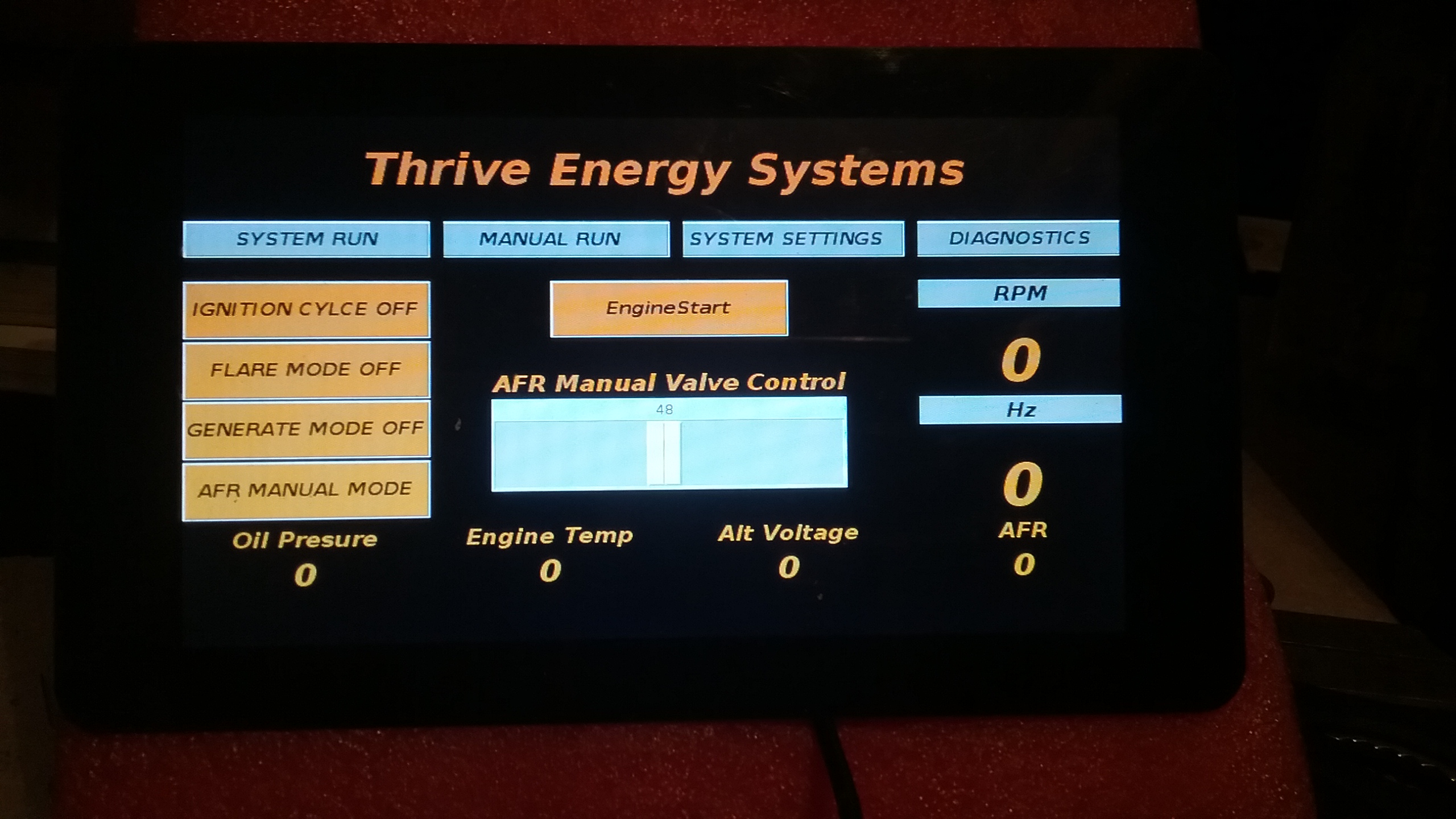
A little sneak peak:
yes, i am working on the AFR to ad,
1 Like
I looked for them, but could not find a suitable throttle with cable… 
but i always can put a cable on the knob for the adjustment
Wayne, its actually after seen your AFR jumpin around that i decided to build this automation
Anyhow, i needed it anyway for my project, so why not share it here 
3 Likes
Hi Michael,
Yup, the auto adjustment at stop and go, the startup
Once this is made easier, more people will switch over or start to build.
If they see that there is a solution for some technical/mental hurdle…
I try to use these hurdle’s as a step stone, not a stumble stone…
3 Likes
Hello Koen .
Hey I’m all for it ! I have had one of those throttle bodes for several years but I didn’t know electronics enough to get it going. ( electronic challenged )
Thanks for showing the process .
3 Likes
Don, Kevin, Michael,
Don’t worry, if i can do, you can do it
2 Likes
How are you homing the stepper motor?
I have some new code Ill post in case you are interested modifying it. Its more responsive and reacts faster or slower according to how far out of the AFR parameters. This code uses a switch to go from manual pot switch adjust to automatic. Might be easy for you to adapt stepper code in place of the servo code.
There is another version of this that runs from I2C and the servo can be ran via a slider GUI widget or you can simply push full auto mode and it fires up the engine automatically; then it switches into auto adjust mode by itself. There is another control module that goes with it and you can run the entire machine in semi automatic or full auto. Between the two controller running over I2C and the GUI in full Auto mode the controller will take the machine from cold start up, switch all valving and fire the machine off. It can light the flare tube on its own and then go into engine run once it sees temp parameters are met. It also has a fail safe if the reactor temp fall below operating temperature it will shut down on its own. Yeah this is why Im so quiet ive been writing software for a solid four weeks 
Edit: Ok Chris I give up it wont cooperate today haha.
#include <Servo.h>
Servo myservo;
// create servo object to control a servo
//VG 02 Wide Band Mixture Controller V1.3
//Craeted by Matt Ryder, Vulcan Gasifier LLC May 5, 2015
//Prior edit; June 22, 2015
//Change log
//April 30,2017 - Todd Harpster
// added contraint to calculated delays after mapping to keep them in range
// read the O2 sensor just once per loop
// add table of expected delays based upon O2 sensor value
//April 30, 2017 - Todd Harpster
// v2 control loop
// refactored code to use mode variable and switch statement to

// This code requires an AEM O2 sensor kit with LSU 4.9 sensor Part # 30-4110

// These constants won't change:
const int O2SensePin = A1; // pin that the O2 sensor is attached to
const int O2SwtPin = A2; //Pin Auto Mode Switch is attached to
const int O2ManPin = A0; // Reads the O2 Manual Adjust Potentiometer on pin A1

// constants for our mode values
const int Mode_Override = 1;
const int Mode_Rich = 2;
const int Mode_Stoichiometric = 3;
const int Mode_Lean = 4;

//tunable parameters below
const int RichCon1 = 700; // Threshold limit for Rich gas condition
const int LeanCon1 = 900; //Threshold limit for lean gas condition
//
const int MinTuningServoPosition = 10; // never fully close the valve in O2 loop mode
const int MaxTuningServoPosition = 180; // wide open

int mode = 0; // loop operating mode
int pos = 0; // variable to store the servo position
int val; // variable to read the value from the analog pin
int lastpos = val; // variable to store the servo last position
int O2SwitchState = 0; // variable for reading the Fuel Mixer Mode status

void setup()
{
myservo.attach(13); // attaches the servo on pin 9 to the servo object

// Need to create a set point for servo start position after manual tuning
{
val = analogRead(O2ManPin); // reads the value of the potentiometer (value between 0 and 1023)
val = map(val, 0, 1023, 0, 180); // scale it to use it with the servo (value between 0 and 180)
myservo.write(val); // sets the servo position according to the scaled value
lastpos = val; // sets lastpos to equal the position of the manually set position
delay(10); // waits for the servo to get there
}
}

//
// O2 Sensor Reading Delay
// ================= ====================
// Manual 10
// Rich 0 - 700 variable 500 - 800
// Stoichi 701-899 500
// Lean 900 - 1023 variable 800 - 450
//

void loop()
{
// read the state of the pushbutton value:
O2SwitchState = digitalRead(O2SwtPin);
// read the value of the O2 sensor:
//Todd - read the O2 sensor once for this loop and store in sensorReading
int sensorReading = analogRead(O2SensePin);

//variable to hold mode for this time through the loop
int mode = Mode_Stoichiometric; // assume O2 reading is not too rich or not too lean, just right
int delayms = 500; // 500 ms delay as a default value - it case it doesn't get changed below

if (O2SwitchState == LOW) {
mode = Mode_Override;
} else {
if ( sensorReading <= RichCon1 ) {
mode = Mode_Rich;
}
if (sensorReading >= LeanCon1 ) {
mode = Mode_Lean;
}
}

switch (mode) {
case Mode_Override:
val = analogRead(O2ManPin); // reads the value of the potentiometer (value between 0 and 1023)
val = map(val, 0, 1023, 0, 180); // scale it to use it with the servo (value between 0 and 180)
myservo.write(val); // sets the servo position according to the scaled value
lastpos = val; // sets lastpos to equal the position of the manually set position
delayms = 10; // waits for the servo to get there
break;

    case Mode_Rich:
      // move the air mixture servo to lean out by adding air
      lastpos = constrain(lastpos+1, MinTuningServoPosition, MaxTuningServoPosition);  // add 1 but make sure it stays in range
      myservo.write (lastpos);                          // tell the servo where to go
      val = map(sensorReading, 0, RichCon1, 100, 400);  // Richer mixtures get shorter delay
      val = constrain( val, 100, 400);                  // Keep values between 100 and 400 ms
      delayms = val + 400;                              // increase delay so minimum is 500 ms - max is 800 ms
      break;

    case Mode_Stoichiometric:
      delayms = 500;                                    // no need to move servo set delay to check back in 500 ms
      break;

    case Mode_Lean:
      // move the air mixture servo to decrease air to make richer
      lastpos = constrain(lastpos-1, MinTuningServoPosition, MaxTuningServoPosition);  // subtract 1 but make sure it stays in range
      myservo.write (lastpos);                            // tell the servo where to go
      val = map(sensorReading, 1023, LeanCon1, 450, 800); // the leaner the mixture the shorter the delay - need to adjust quickly
      val = constrain(val, 450, 800);                     // keep the delay between 450 and 800 ms
      delayms = val;
      break;

    otherwise:
      //this shouldn't happen
      break;
  }

  //wait for a little bit before doing this again
  delay(constrain(delayms,250,1250));                 // use contrain to be completely sure delay value is reasonable
}
3 Likes
Hi Matt,
Yep, your’s is servo, mine is stepper or PWM (i have both, different throttle body’s )
The automation/positioning, in my case, can be done with either return to manual defined spring ( position adjustable with a “wrench” ) or, more advanced , with a potentiometer allowing adjusting the AFR as desired from the cabin.
In shown case above, Stepper motor, the Analog 0 in, reads the voltage, 0-5V , from the Potentiometer.
The stepper follows according the voltage, the power from the stepper only set slightly higher then the return spring power in the throttle body. In the program i can modify the lenght off way for the stepper, the reaction time, the speed, and also the treshold to ignore low fluctuations.
If we determine the perfect AFR at position X, locking that mechanicaly with 2 springs ( mechanical zero )
Then the voltage from the AFR meter set ( 0-5V) will send the mixture valve in either direction as needed.
( to be build and tested before actual showing of )
If i compare with 2 analog reads , 1 from potentiometer, and another from AFR value
i can steer the Mixture valve according the Potentiometer setting.
The PWM set would be on the same basics, working on that now.
I hope to be able to split this topic into different builds/subtopics ,so things stay clear.
I will try your setup as a studycase for my learning, if i find something i will let you know.
Edit:
Picture with the output voltages from the AFR set i use
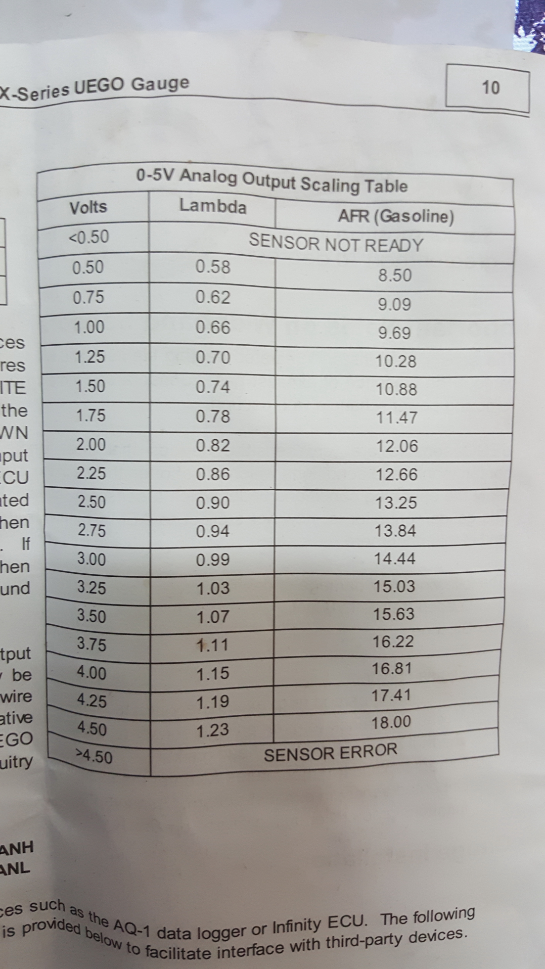
1 Like
Thats pretty cool, what i have found is 650 bytes to around 750 bytes is about write for wood gas. this is slightly leaner than the engine running on gasoline.
Ever tried a EGT readout at the same time as powerincrease and mixture control ?
I am working on that now to
Ive generally purchased the AEM kits and use the DRO on the gage. However, since Im running an Rpi with 7" touch screen those expensive kits will probably be going away and Ill map the sensor read out 0 - 18 and send over I2C to the display. It will have most engine vitals displayed this way as well. Oil pres, temp, alt/ batt voltage etc.
Id send some updated pics but really need to clean up the wireing first. looks like a rats nest right now. I will be installing shielded wire here soon as I wrap this thing up and clean all that up.
2 Likes
Hey Willus!!! Whacu talkn bout???
5 Likes