Got the printer to assist drawing functions initially…
First we have to set the mind to what a blasting nozzle really does!
Most have in mind what happens ahead of a blasting nozzle in the open.
The beam rips with it and pushes a lot more than the beam flow itself.
All this added volume comes in from the sides, and in a closed passage, from behind.
So, a nozzle-beam does not transport anything else, if the admittance to the beam is “prohibited”!
Now, if the nozzle blows a beam in a compact char-mass,
it burns a “channel” for the rushing insucked gases and air toward the hearth center.
The char constitutes a real resistance for the gases to be sucked in by the beam.
But we can help this “inflow” driwen by the sucking beam! And benefit the pyrolyse gases rehandling!
With a ringformed cavity around the center-glow, the out-streaming gases are easily re-routed to the sucking beams instead of sneeking down toward the restriction.
A loose metallic cylinder stands on the nozzle-shafts, and in the upper end a conical metal ring is welded to this loose cylinder.
Easily removed upwards for cleaning, if the silo funnel is kept high enough and it also is removable.
Let’s see if the nozzle-area picture can be transported; the acceptable transport programmes have been changed again… jpg, jpeg, png, gif.
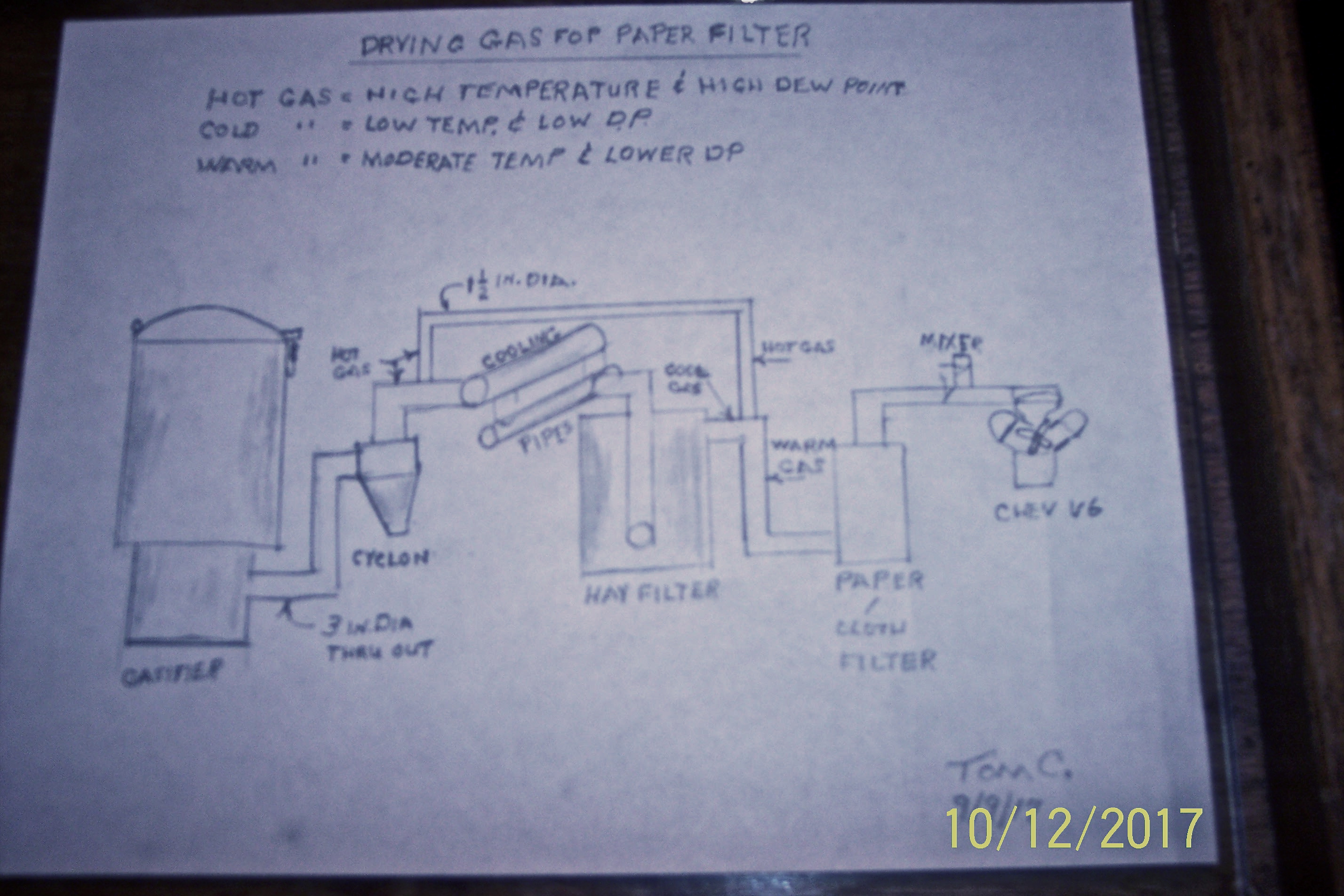
Hi Tom I just read your post about what you are planning to do with your gas routing. Tried to move the quote to here but was unable to. Anyways could you draw up a sketch of what you are planning to do. It’s not clear to me by what I’m reading, probably on my part not yours. Just make a paper sketch take a picture of it and post here. I think this is something I might want to do on my truck or my new one in the future. Oh yes I’m looking for a bigger work truck to put on wood gas. Up here trucks are very expensive and are all wore out before being sold for a decent price. No salt so they last along time. Thanks.
Bob
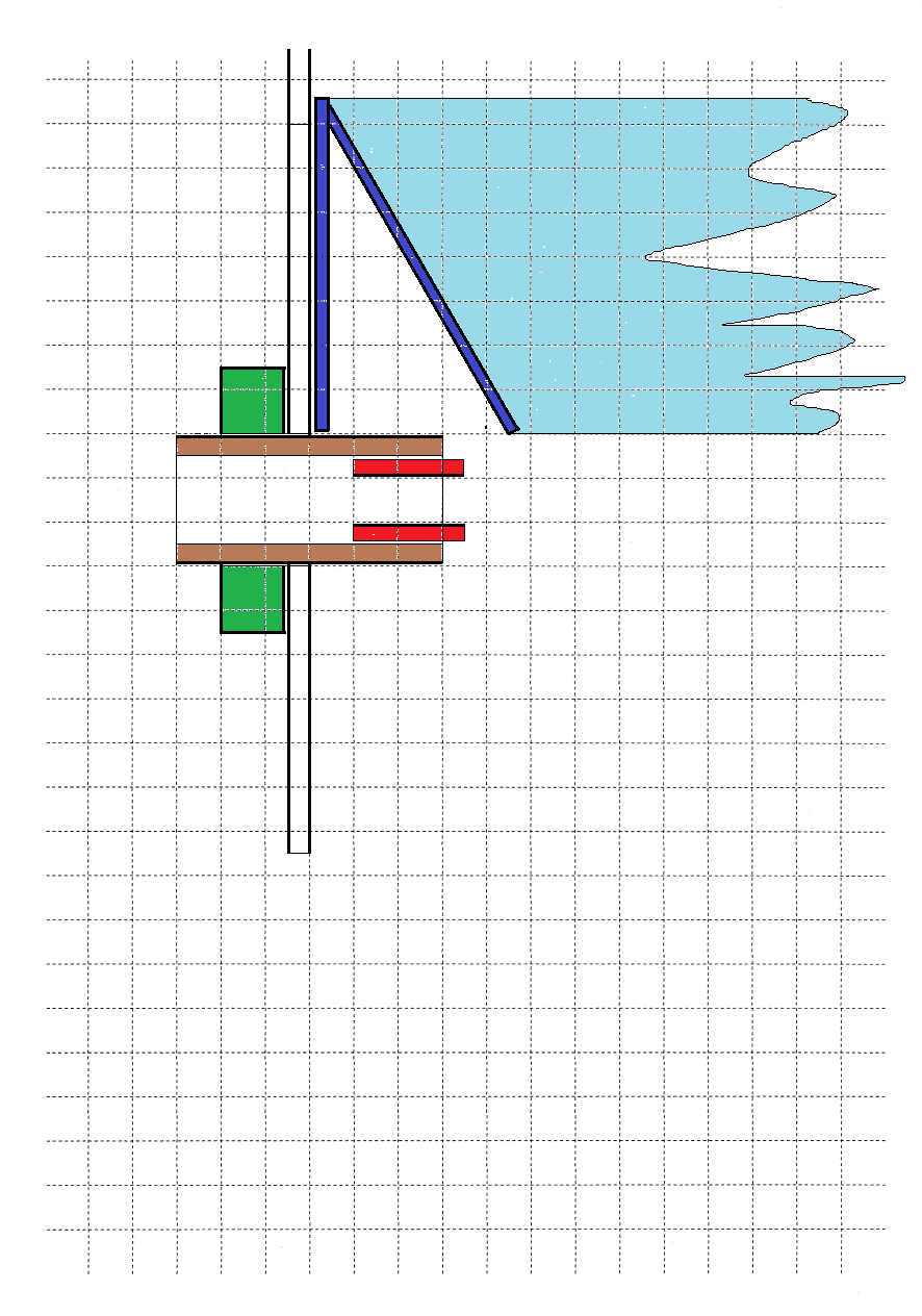
From what I understand you plan to partially bypass the cooler and mix in that warm gas for reheating further downstream, right?
I see one problem. The bypassed gas misses the oppertunity to shrink and drop its moisture.
I think the easiest way would be just to steal exhaust heat on the way up front. I think I will weld a new muffler with two extra pipes in it. One for air preheat and one for gas reheat.
You are correct JO. But what are we trying to do here?? I am trying to get the gas through a paper filter to get rid of soot. I would like to lower the moisture in the gas but if I can’t do that then I want to lower the dew point to get through the paper. Yes eventually I will plug the filter with moisture and caked on soot. In the mean time I should get much cleaner gas to the engine. Worrying about the moisture alone will not help your soot problem if you have any.
I had very little room to get my 3 inch pipe from under the truck to the top of the TB. The 3 inch pipe laid against the exhaust manifold and the frame. So I replaced a section of plastic pipe with some thin wall 3 inch pipe. I did it to prevent the plastic from melting but now find I am getting some gas reheating. TomC
Tom, if you are reheating the gas, put more of the tube on the manifold to heat the gas to go to the filter. But have the filter up front. Filter it in the engine compartment then into the TB. Or have the filter box infront of the radiator or some where it can be serviced and changed out. Have a hot filter in back and paper filter up front. Just a thought. I’m new to this paper filtering but I can see the advantages if you can make it work. I’m still working on my hot filter. Wiill show it off when I get it done.
Bob
Andy, go to Craigslist then to some place likeMemphis and look under cars and trucks. I’m sure you could find a good truck BUT they are not cheap. You may even think they are expensive TomC
Hello woodgasers; You know I have been having quite a discussion on cleaning up the gas for my engine. Seeings Max is our resident expert on Imbert style gasifiers and accessories, I have gone to two of his threads to learn. One on the Audi and the other on a Nesson Micra (?).
The following is a portion of his post;
On the Audi the gastube has to make a bend over the open trunk lid and in the summer go parallel with the 1,1m long “dishtable basin” (?) to its front “gabel” (?) in order to get enough cooling to dew point. In winter, it is led in to the basin from the back “gable.” (?)
So, this is a wet system with two matress pieces of open cell matresses
superposed on each other with ss net under and above, to form “manifolds” to spread and collect the wet gas.
“Basin”(? I suppose that that has a top on it.) measures: 110 X 50 X 20 cm.
About 1" inside the back “gable” there is a bulkhead “(avoiding low corners)”(?) to collect the filtered gas from above the upper ss grid on the mattresses. It is taken out near the lower right corner, fed back to the “gasgenerator righthand lower part for last condense separation”(?) before rising up for re-heating in a “smuggler cannister”(?) before final paper filtering on the back side of the gasgenerator.
(identical bucket as for the twin cyclones). From there over the rised trunk lid on the right side of the basin to the right hand windshield pillar and down into the right wing and finally into the motor compartment.
Condense is taken out from the basin in the righthand lower corner with a 1 1/4" rubber tube to the bottom end of the “condense separator” (?) for the gas at the gasgenerator’s righthand lower part. (There is an internal bottom between the condense separator for gas and the condense tank proper). They have individual draining.
Can someone understand this and make it clearer to me? Skizzes, sketches, or pictures would help. TomC
Ok, let me try another question. I am testing my system for air leaks using vacuum. I start out with my kirby vacuum pulling 16 inches of H2O. When I check the vacuum at the mixer box at the engine, I have only 3 in. My question is NOT, “why do I have such a loss”, I will have to sort that out. But my question is " why when running on woodgas, do we get a reading on the cross rail of three times that of the fire box?" When testing I start with the 16 in. then anything I add affects the entire system. Starting with 16 if I add my hay filter, the vacuum coming out of the Kirby drops to 14 and the vacuum coming out of the hay filter is 14. No difference. If I add to that my cooling rails I get 11 at the Kirby and 11 at the cooling rails out let. No difference between the start and finish. So how do we get the rails to read three times the fire box.?TomC
I never trusted vacuum readings when testing for leaks. I always use soap solution with low pressure air - low enough to not blow the bubbles to pieces.
Yes Don I agree, always used soap and pressure. This all started when I tried to start and flare the gas generator. Couldn’t get anything to happen. Not even smoke in the hopper. That was unusual, so I started this journey of taking the system apart and trying to test each part of the system. I did find two leaks so maybe I will put it back together and see what the engine will pull. TomC (individually I have not tested the cyclone alone or the generator itself.)
Tom, I´m not completly familiar to your vocabulary, but I guess you by “firebox” mean somewhere in the nozzle region or hopper.
As I understand it the difference in vacuum represents drag created by the charbed and its chemical activity. I like to think of the hopper vacuum as the vacuum nozzles are seeing.
With an extremly tight charbed hopper vacuum will be close to zero and you will peg the rail guage. With an empty gasifier the readings should be about equal.
Maybe i missunderstood your question. Feels like I´m kicking in open doors here.
Hello JO. When you say it, it makes perfect since. I have one vacuum gauge in the cooling rail and the other is in the ash area by the grate. From what you are saying, I should have the one in the hopper instead of the ash pit.
But I still get that 2 or 3 to 1 ratio of rail to ash pit. Hmm. Seems with my set up the rail and ash pit should always read the same.
Quick description of my problem. I have a “Y” with two legs taped off and the kirby vacuum in the 3rd leg. A tap in the “Y” reads 16 inches of H2O with Kirby full blast. Now I hook everything up to the “Y”, with tape across the air inlet to the gasifier and tape across the outlet from the mixing box under the hood; the vacuum reading at the tap goes to 3 inches. Go back to the “Y” and tape one leg off and connect the hay filter to the other with the exit to the filter taped off-- 14 inch reading. Then remove tape from filter exit and put a 7 ft piece of 3" pipe on the outlet with tape on the far end— reading goes to 13 inches H2O. And down and down it goes as I add cooling lines, cyclone, gasifier, and line up to the mixing box at the engine. Ending in the 3 inch reading.
Can’t believe I have consistent air leaks through out. The 7 ft pipe I took out and made sure there were no leaks.
Tomorrow, I will pressurize the system, but the little I got done on that project tonight showed it ain’t going easy. TomC
Hmm l am not quite sure what to think of your problem. You shuld have roughly the same vacuum after the gasifier. Cyclone takes about 2" if l remember right, not sure of the filter but the rail and gas suply piping shuldnt be wery restrictive. Soot plug perhaps?
What JO sayd. Allso a note. Same quantity of gas trugh a cold gasifier hearth expands 4 times once the hearth is fully heated. Thats a lot more drag.
Maybe I am confusing this whole thing because I am measuring “static” vacuum. I section off different parts, starting at the kirby, by taking the system apart and putting a plastic bag over the end of the pipe where it is disconnected. ( all vacuum readings are taken at the “tap” in the “Y”) The difference between the reading at the intake to a part and outlet, should indicate the amount of air leak. BUT, the 7 ft piece of pipe I checked very carefully before installing and yet I lost 1 inch of vacuum in it. indicating a leak.
I’m going to pressure test it like Don recommended. Being an OLD tire man, I have used that method a million times on tires. The problem is getting pressure in the system. Last night I put a air chuck connector in the cooling rail and taped the intake air to the gasifier off, and taped the pipe coming out of the mixing box to the throttle body. Set my air compressor at 2 PSI and connected the hose to the air chuck. I could hear a “bad” leak in the gasifier, particularly the hopper. What is in the hopper that could leak and where is the air coming out. After going to bed, I figured that out. The air flowing into the hopper was making the noise and it takes a LONG time to fill a 50 gal. drum with water if you are using a 3/8 th hose. That is what I was trying to do with air. The sogga to continue. TomC
Hello Tom.
Just another thought on leak checking.
I worked in the high vacuum industry many years ago and one way we checked for leaks was to pump the system down, then seal it off (closing the valve to the pumps), while measuring the pressure (vacuum). If there are no leaks, then the pressure won’t change.
Thanks Pete. That is what I was trying to do. Seal off both ends and pull a vacuum, but I couldn’t get it to hold, it leaks down so fast it takes a constant pull.
You just made me realize, that I am pulling a vacuum, but then I just shut the electricity to the vacuum source off. I should have shut the valve to isolate the vacuum pump from the system if I want to hold a vac. It was probably beading down through the vac.pump itself. Thanks TomC