I would tack it in place inbetween every nozzle and then punch down a small slope above every nozzle. Any expansion and you have shown the buckle where to go. Also the tar drip (if any) will end up where it’s supposed to - in front of the nozzle tips.
Since I’m using replaceable heat shields, my plan for my next build (if any), is to incorporate the “cap” into the shields. The cap will most likely wear down eventually in that super hot enviroment. Just thinking out loud.
Hello Max;
Yes, memory problems do come with old age, but not this time.
Please read my post, before commenting so that I know you have given some thought to the problem. I have since decided to remove a small amount from the ring and allow it to be loose when cold, but will expand when heated and tighten up on the fire tube. TomC
Tom i dont know if you are building a fema,€ or imbert, are you building more of a WK design then the other imbert you had built. If the burn tube was big enough you could try the ceramic blanket effect as paul and justin did and had good results with turn down ratio and perfomance.
The thought of a ceramic blanket gasifier has been on my mind, but for now I am just rebuilding my Imbert. If I was going to build a ceramic type, I would not have a “burn tube”. I would make a oversized cylinder out of about 18 gauge sheet metal and form the ceramic to the inside of the cylinder. THAT would be lite TomC
Mr.JO, I think I remember seeing a picture of the inside of you gasifier and you had plates around each nozzle tip. Are those the “heat shields” you are talking about? It is late, so tomorrow I will have to go to your postings and look at the pictures again. I am wondering why you need any heat shields TomC
Please, pinpoint what thread and date. Sofar I have found nothing of the sort. The only thing on my mind reminding of rings, is Kristijan’s double ring “of fire”, but that has nothing to do with your single ring on the nozzles;
Kristijan’s rings are a part of the air distribution, your’s is “behind” the blasting nozzles!
Yes, post 35.
At the time there was a lot of talk about wether short nozzles, in a high velosity Imbert, would make the firetube wall to hot. Carl mounted shields in his gasifier after the rebuild with good result and I thought why not. I haven´t seen any damage on mine so far, so maybe I could have done without. They are only 2 mm thick and the same material as the firetube.
Mr. JO; I was up 'till after midnight looking for the picture of your heat shields. Scrolled from 800+ post all the way down to #35 to find it. Then I went to Kristigan’s thread to look up something else, and about 4 post back I found the picture again. You had posted it to his sight to make a point.
I hope you are wrong about the short and long nozzles, because I have gone from long nozzles to short-er nozzles on this build. ( recently I was referred to as Mary the Contrarian because I tend to go the opposite direction of the crowd.)
My thought on the short and long nozzles is; It is not in the length of the nozzle but the type of gasifier the nozzle is used in. In an Imbert style, the air comes in at a high speed. It will go a short distance outside the nozzle tip before it mixes with the pyrolisis gas and ignites into a very hot flame/glow. This allows the tip to stay relatively cool.
In a WK style, the air comes through the nozzle at a much slower speed and thus mixes with the pyrolisis gas right at the exit to the nozzle. The heat from this mixture will heat the end of the nozzle thus causing a deterioration — like a cutting torch in metal.
Time will tell.
In the meantime, I guess I have to work on that “tar ring”. I was hoping that you Imbert type builders that were involve in the discussion, would tell me if my picture depicts what you understood the discussion to be. TomC
Pretty close from what I understood of that discussion. I may have imagined the balcony protrude a bit more, past the nozzle tip and about 1/4 inch above it. I don´t know if it really matters though. The tar drip will most likely get sucked into the air beam anyway. But as I mentioned earlier I would tack it between the nozzles a bit higher and hammer it down above each nozzle to the wanted 1/4 inch distance (Make it look like a corrugated roof tin).That way the tar drip will be directed to just in front of each nozzle. I don´t think it has to be welded all the way around the firetube. Any small gap towards the wall will carbon up and a lot easier to replace or correct the balcony without damaging the firetube if not fully welded.
Remember, this is only my personal interpretation of the previous discussion. MaxG and SteveU presented the original idea.
Allso, longer nozzles are important as there is no heat recovery from the firetube so you need to draw heat awayfrom the wall.
With a wk, and my build allso, heat is recovered back to the air, so the sistams can have no protrudeing nozzles.
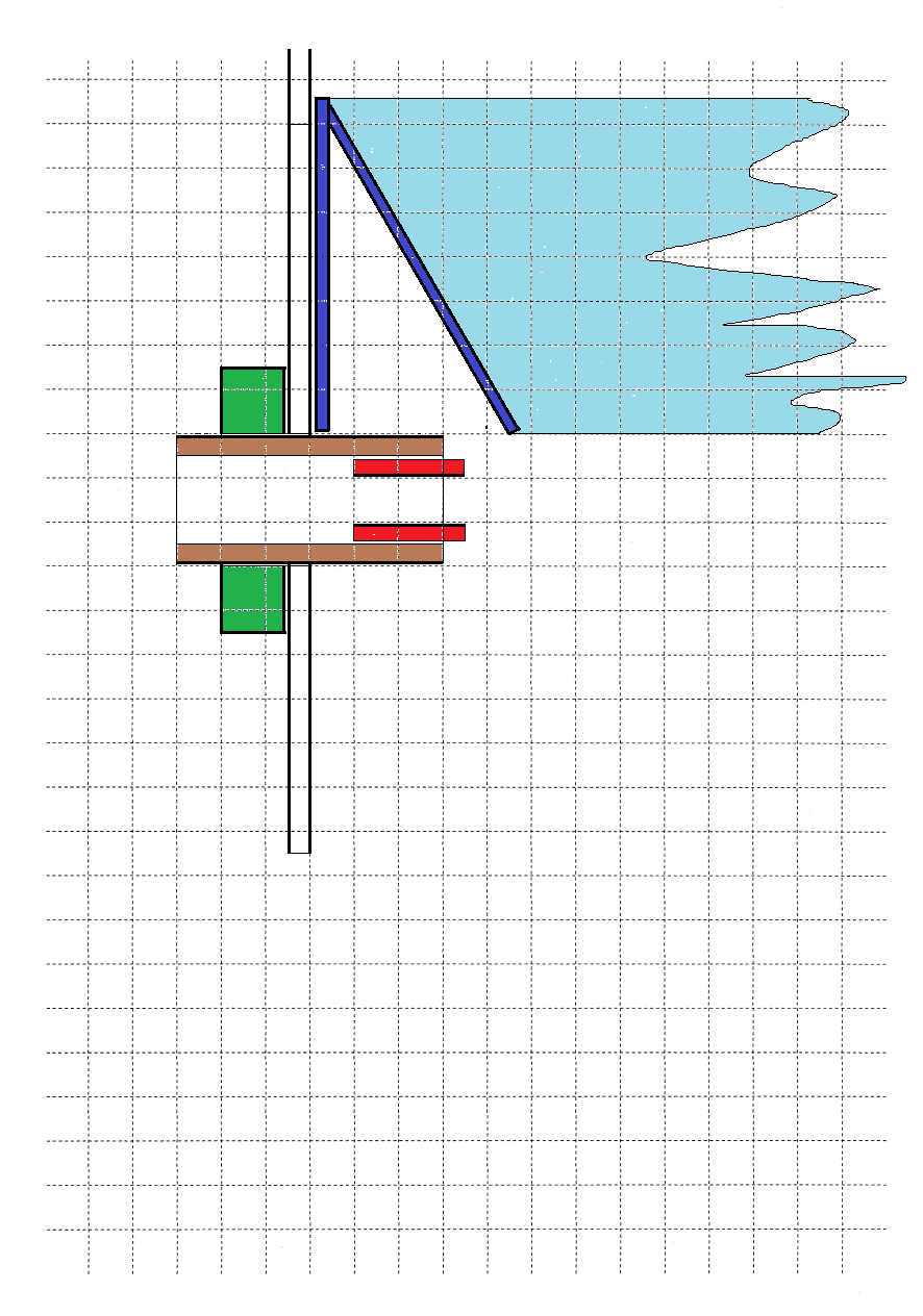
Got the printer to assist drawing functions initially…
First we have to set the mind to what a blasting nozzle really does!
Most have in mind what happens ahead of a blasting nozzle in the open.
The beam rips with it and pushes a lot more than the beam flow itself.
All this added volume comes in from the sides, and in a closed passage, from behind.
So, a nozzle-beam does not transport anything else, if the admittance to the beam is “prohibited”!
Now, if the nozzle blows a beam in a compact char-mass,
it burns a “channel” for the rushing insucked gases and air toward the hearth center.
The char constitutes a real resistance for the gases to be sucked in by the beam.
But we can help this “inflow” driwen by the sucking beam! And benefit the pyrolyse gases rehandling!
With a ringformed cavity around the center-glow, the out-streaming gases are easily re-routed to the sucking beams instead of sneeking down toward the restriction.
A loose metallic cylinder stands on the nozzle-shafts, and in the upper end a conical metal ring is welded to this loose cylinder.
Easily removed upwards for cleaning, if the silo funnel is kept high enough and it also is removable.
Let’s see if the nozzle-area picture can be transported; the acceptable transport programmes have been changed again… jpg, jpeg, png, gif.
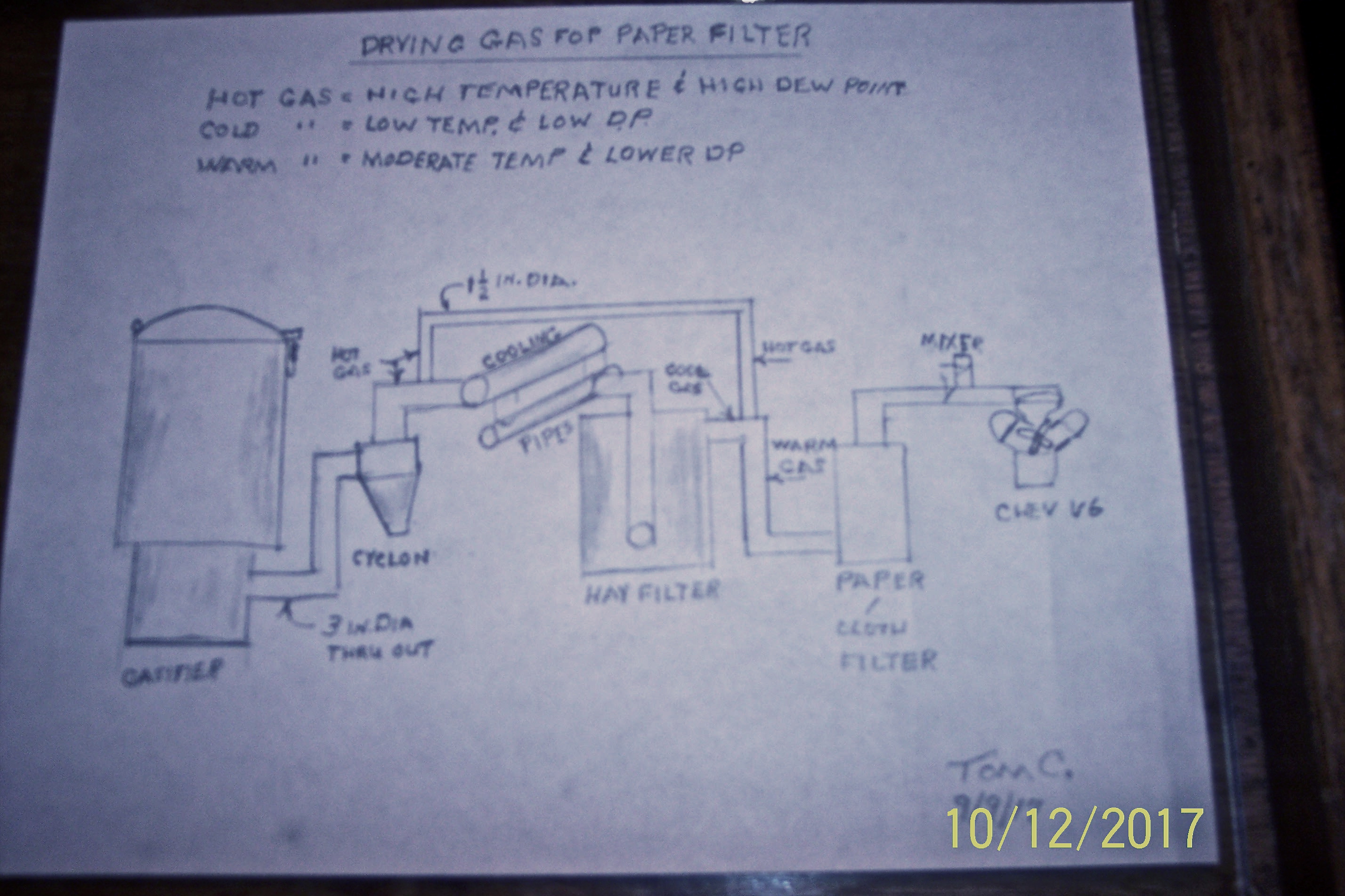
Hi Tom I just read your post about what you are planning to do with your gas routing. Tried to move the quote to here but was unable to. Anyways could you draw up a sketch of what you are planning to do. It’s not clear to me by what I’m reading, probably on my part not yours. Just make a paper sketch take a picture of it and post here. I think this is something I might want to do on my truck or my new one in the future. Oh yes I’m looking for a bigger work truck to put on wood gas. Up here trucks are very expensive and are all wore out before being sold for a decent price. No salt so they last along time. Thanks.
Bob
From what I understand you plan to partially bypass the cooler and mix in that warm gas for reheating further downstream, right?
I see one problem. The bypassed gas misses the oppertunity to shrink and drop its moisture.
I think the easiest way would be just to steal exhaust heat on the way up front. I think I will weld a new muffler with two extra pipes in it. One for air preheat and one for gas reheat.
You are correct JO. But what are we trying to do here?? I am trying to get the gas through a paper filter to get rid of soot. I would like to lower the moisture in the gas but if I can’t do that then I want to lower the dew point to get through the paper. Yes eventually I will plug the filter with moisture and caked on soot. In the mean time I should get much cleaner gas to the engine. Worrying about the moisture alone will not help your soot problem if you have any.
I had very little room to get my 3 inch pipe from under the truck to the top of the TB. The 3 inch pipe laid against the exhaust manifold and the frame. So I replaced a section of plastic pipe with some thin wall 3 inch pipe. I did it to prevent the plastic from melting but now find I am getting some gas reheating. TomC