No Im planning on metering in air into the intake of the gasifier. It will be controlled to have a static pressure, or a slight vacuum during loading, I don’t want to have any positive pressure on the machine just want to alleviate the vacuum. The waste will get directed back to the engine’s air intake and also our 3rd stage reduction also new in development.
I could go a less expensive route for this part, but we will need some pressure for the Fischer / Tropsch process.
I’m all for research and innovation, but F-T is big mountain to climb. There have been people that have spent 10’s of millions of dollars on this with nothing to show for it. You likely know this, but the biggest challenge you may have is the gas composition of woodgas from an air-blown, atmospheric gasifier. Over half of the gas is just nitrogen (N2) which carries through from the atmosphere. Most people working on F-T are using steam or oxygen blown gasification that results in syngas with much larger relative volumes of hydrogen and CO. Good luck, and I would be very interested in meeting you sometime; fellow Michigan boy here working on larger scale gasification of solid waste. Cheers!
Some of you that made it to the event may have seen tinkering with this little machine. Couldn’t get it to work I was working on this and had to finish building it at the event. So I didnt get any run time here or even a chance to debug it. Well of course there was leaks lol and then some issues with the servo. I think the rain might have wiped it out.
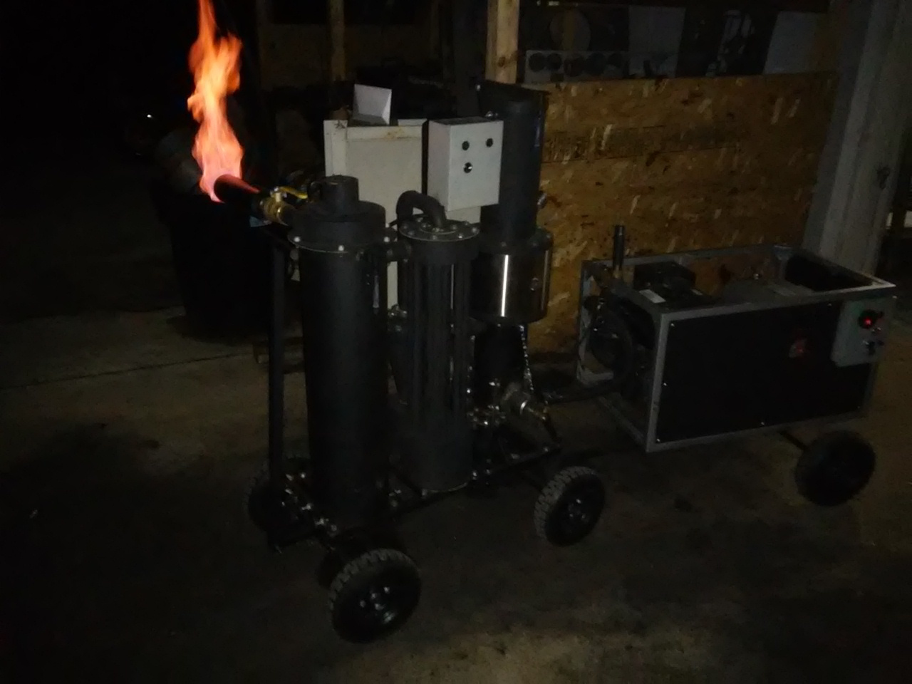
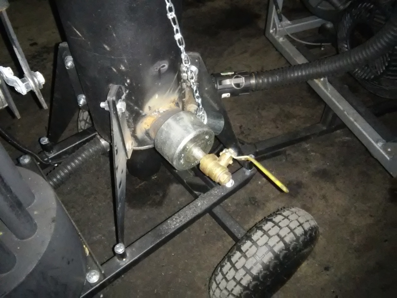
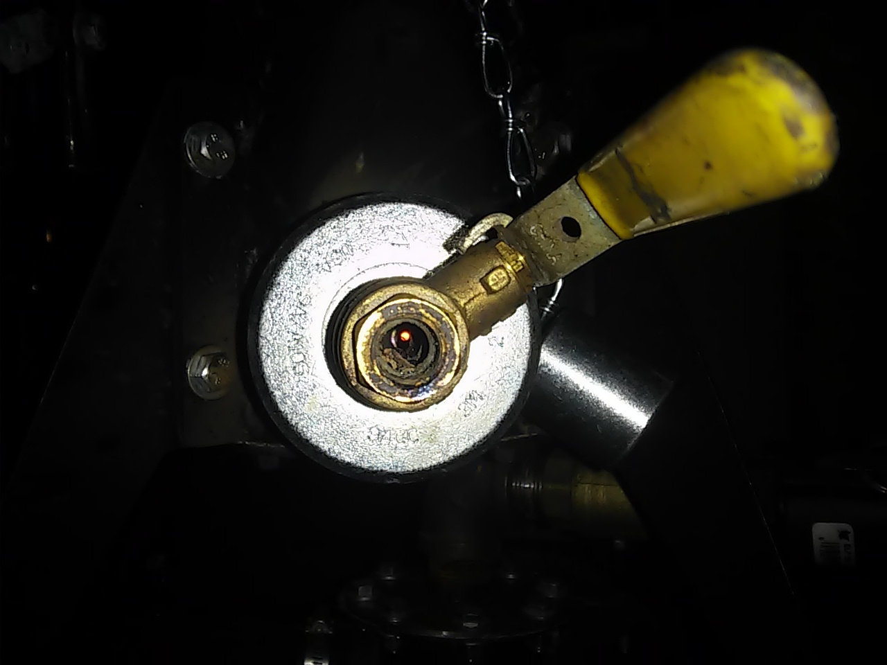
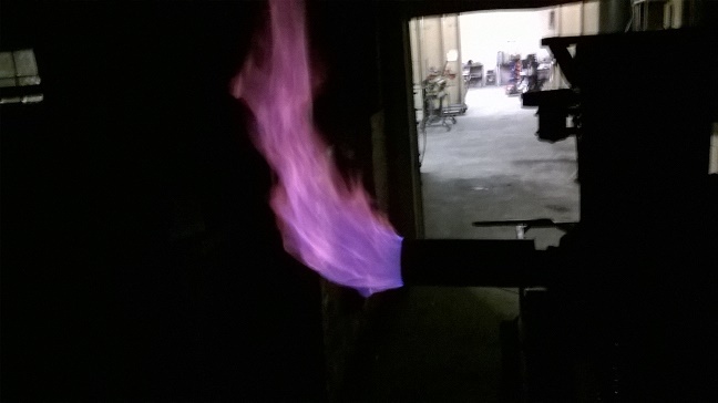
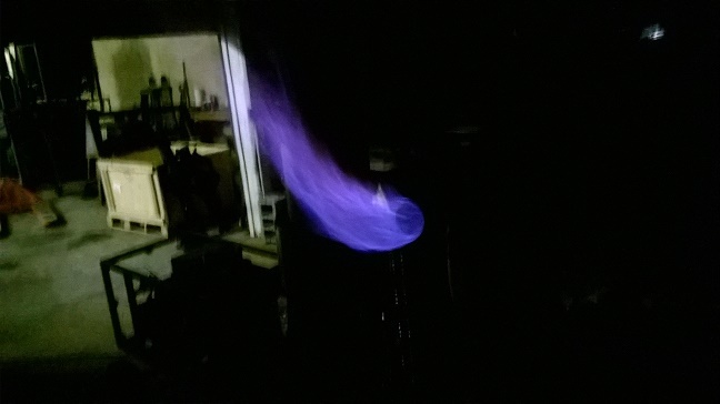
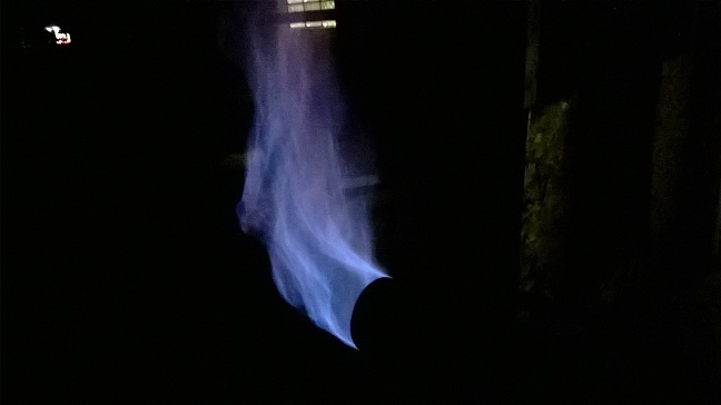
So I took some time to fix it today so we can get started on new development. First thing I wanted to try and was an easy one; is adding in a simple fire system into the ash pot. Reasoning for this is our customers that want the big systems do not want to mess around with emptying condensate, media filters or the ash on a daily basis. So why not just burn it off and reduce it to ash, if I can get this to run linear to the char yield or just below this should greatly decrease the intervals for ash clean out. The bonus is this will also add some efficiencies and add heat to the primary and secondary reduction systems. When I get the turbo air will get branched off the intake of the gasifier and Ill add in the EGR then. I may still implement a removable auger system to this as well.
So far this is working pretty well, Im keeping my distance though lol
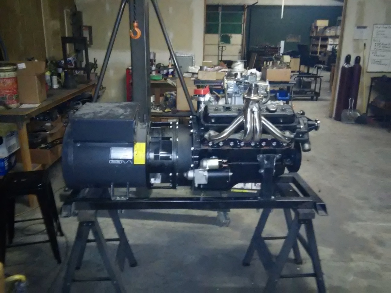
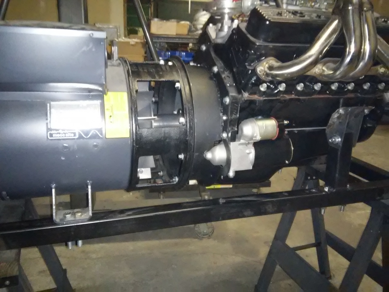
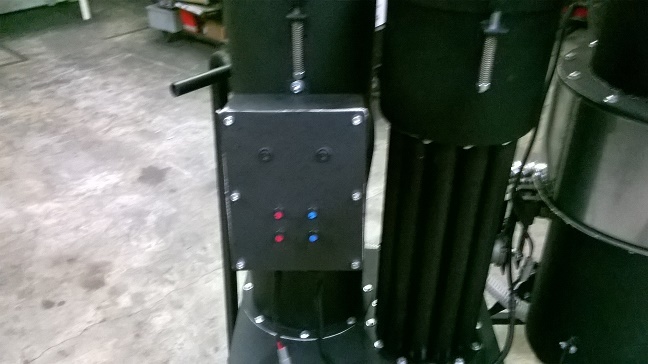
More evolution, so as you know we build our generator systems in house. Im not 100% on this but I think we are the only ones. This maybe as building a generator in this caliber of size is well a bit of a challenge. One big challenge is mating up an engine to the generator head. In the past we specially machined LoveJoy spider couples, this worked well but this limits us to the more expensive dual bearing heads and limits whats available. It also just did not look manufactured. So the challenge, is to source an SEA 4 bellhousing that will bolt up to the GM 90* bolt pattern. There were some options out there; however, there were just way to many unknowns for a very expensive part that no one could guarantee would work for us.
So I built my own!!
What I had to do was build a very high precision fixture, I purchased a Chevy to Buick bellhousing adaptor plate to use as template. This is so we can very accurately transfer the GM dowel holes over to our bell housing plate. We CNC the both the SEA 4 flange and also our GM mnt plate. But the CNC is not quite accurate enough for locating the dowel holes. We need to be less 0.001" center on those dowels so this plate makes it very easy to do. I built a fixture system on our mill and dialed this in to less than a thou tolerance. I built another plate to locate holes for the generators flywheel to the GM pressure plate. Im using the 11" pressure plate use clutch bolts holes and dowels for mounting this jig. Then we transfer punch those over, drill and then tap.
Once this is all bolted up we then align the rotor shaft to the engines crank to a thou our less.
End result is it looks like we bought it!!
Now that we have this fixture we can duplicate it and this opens up a lot of different options for us.
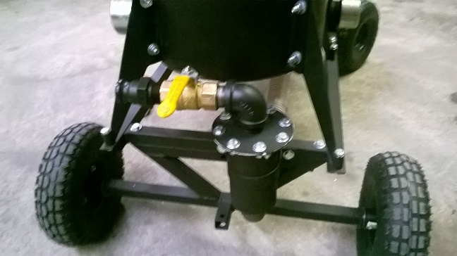
Hey Matt, nice work, looks very pro. Had a question on the mounts why no rubber? I have a 17k, and a 25k gens both are 4cyl. engines with very heavy rubber mounts, not questioning your engineering, just wandering if it is needed to keep from cracking the frame. Al
The frame in the picture sits on rubber mounts. The engine and generator need to be solid to one another or all kinds of really bad things will happen.
This will sit on the main systems chassis on six beefy isolation mounts
Great accomplishment MattR
Look into the different available commercial power transfer couplers available.
Very hard to get, and maintain the precision needed to not an a few hundred/thousand hours not knock-out/wear-out a bearing. Why OE’s use a flex plate coupling.
Yeah Steve already been down that road. Nothing is standardized and none of those manufactures could give us a solid answer on what would work. We would just have to buy things and through parts at it until we got it right. By that time we would be bankrupt trying all the different housings, star drives and everything else that is available.
This fixture I built is very accurate, I have now dedicated our mill for this job. When this is all bolted together I dont rely on dowels or anything to center the rotor to the engine. We dial this in manually with a 0.0001 dial indicator. So it is perfectly centered when done.
Oh believe me I know all about bearing mis alignments. This was my job when I travelled as a service tech. The machines we built were high precision multi axis grinders. The Z axis on non counter balanced machines had major issues with bearing and ball screw failures. When I first started my position, I found that there were some discrepancies with the alignments this didn’t go over well with me being the new guy vs guys in the shop and engineering. haha. When the machines were manufactured they were aligned with the Z axis column laying on its back. Gravity is a very bad thing when it comes to high precision and was affecting the alignments pulling on the ball screws and also affecting the readings of indicators when sweeping surfaces. I developed my own tooling for working out in the field to perform new alignments. The company completely redesigned the drive systems and also alignment procedures once my realignments stood the test of time. This was major battle for them.
Excellent answer MattR.
If I may re-phrase:
“We build our systems one at a time, Craftsman one at a time individually hand dialed in to not need these mass production fixes.”
Pride converts the worker into a caring craftsman.
I had my unit builders actually in metal sign their works.
Best Regards
Steve Unruh
Yup even if we do get to that point I dont think this will change. This really was pretty easy to do only took a few minutes to tweak into place. The bolt holes in the pressure plate are close enough to get a good starting point. I was even in the full range of the indicator at the start. I think its range is something like 15 thou. Just zeroed it at TDC spun it 180 and split it. Continued this two more times and I had it.
We will put this into a procedure for out in the field too.
Yes I had though about that. Still need to test it, but yes a very good possibility we may offer this. An SEA4 to Chevy adaptor does not exist!! You can get there but it requires more than one adapter, and then that complicates the fly wheel couple.
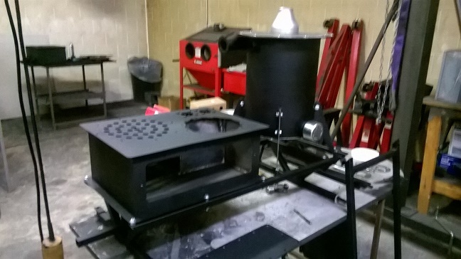
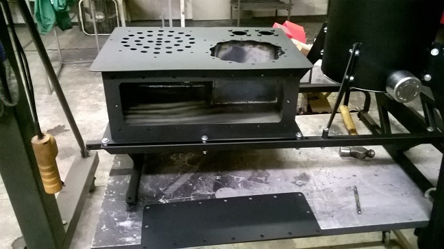
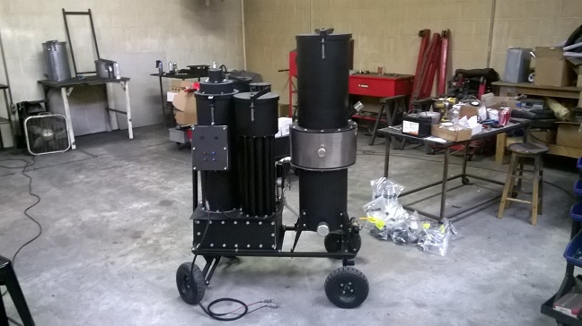
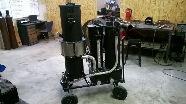
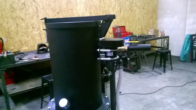
Hey all, well for the first time we are ahead of the game. We are getting the 2016 models ready for pre release this year. Next year we are going to revert back to just two versions of the M-Series the (M-Series I and M-Series II). Next years M-1 will be based on what is now currently the M-II with the 8" hearth and the 2016 M-2 will be based on the current M-IV with a 12" hearth. We are very pleased with this years M-IV’s performance; so not much is changing for the gasifier / reactor portion. The big changes for next years M-Series is the filtration. We have come up with an easy to service system that will allow the full cleaning with minimal disassembly. The filter tank now integrates the complete filtration into one unit, but is still modular in its design. So replacement parts will be simple, easy and inexpensive to replace. This will also allow us to offer different materials for certain portions of the filtering system later down the road. I am going to build an aluminum condensor core later on to experiment with. This will be a thick wall aluminum tube condenser, even if we went with 1/8 wall tubes this would still be more effective than 16 ga mild steel. Aluminum has a unique property that makes it dissipate heat faster than it can absorb it. But that will be an experiment for a later day The cyclone is gone for next year, instead a two stage filter will take its place and should prolong the dreaded full cleaning services. There is a simple coarse filter placed before the main filtration with a bin for emptying coarse ash debris and then a finer filter is placed at the top of the condenser to catch anything the first filter misses. We are going to explore different non combustible filter medias for this. Insulation and lava rocks are the first things we are going to try. In addition the wheeled chassis kit will be standard again and new for next year will be the automated grate and hopper agitators also standard equipment. The arduino mixer may also find its way as standard equipment along with other advanced automation we are working on as well. We will need to develop the O2 mixer with the narrow band sensors and then I think it will be cost effective enough for us to be able to offer it at minimal cost added.
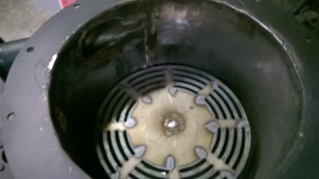
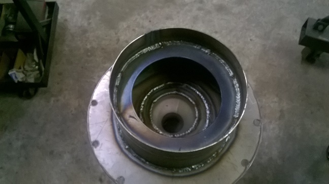
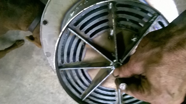
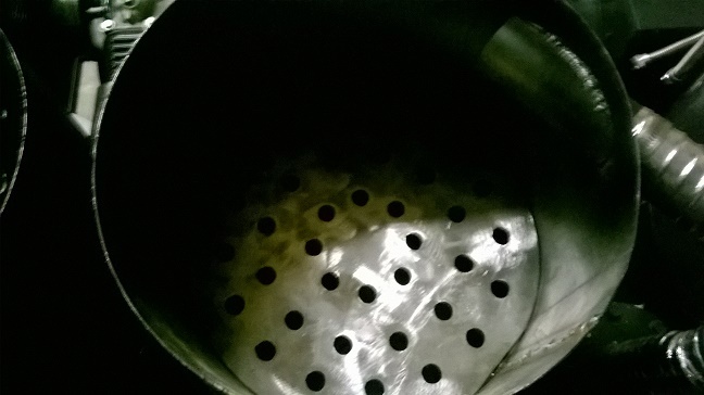
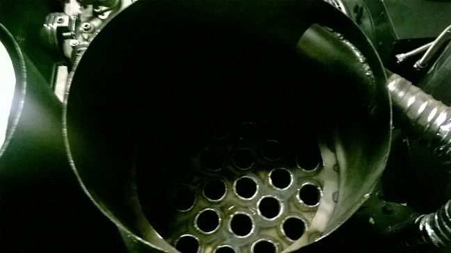
In the pics you will see our grate reduction design. This is a simpler two stage reduction system that is similar to the ES versions. The grate is not fully vented and you can see we have a sill placed in the reduction skirt. Above this is the first stage down draft reduction. Along the side ash builds up here creating a natural insulation, along with other theory. The lower portion the gas is then pulled in a cross flow direction. Rather than going straight down and packing the gas and char is pulled to the sides loosening the char bed while maximizing carbon exposure. This has allowed us to double the size of our reduction while improving flow. Something that was not anticipated is there is a dramatic reduction is ash yield. We used to have to clean the ash out about every four hopper loads. This has about doubled, we can run all day and not have to worry about it.
This hopefully will be the last design revision for the M-Series for many years to come. We will continue to make this machine better and better with more advanced automation. This along with advanced manufacturing methods are what we are working on to get the 2016 M-I and M-II developed for retail. As soon as we get our manufacturing to this level and the electronics to make these machines self run we will approach retail sellers with this product. How cool would it be to see a gasifier on display at your local Cabela’s?!?!!
The ES- Models I am still working on. The ES-4 version is pretty well ironed out. Next is the 5 kW version, I am going work on reducing its cost dramatically. In order to do this I will need to design this with some options, an air cooled engine vs the very expensive liquid cooled option and also offer it in an AC version. The liquid cooled Kohler and all the components for the DC system is what really drives the cost of the current machine. I can cut the MSRP down to around 12k for this guy if we go with the less expensive air cooled engine and AC system.
Also in the pics is our ES-4’s massive reduction bell
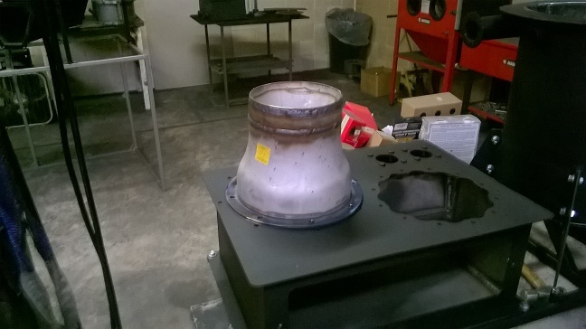
Hey all well a change of plans, This new M-IV is getting a re badging for next year. We are going eliminate this design for the Micro series and launch this as a new product line. After doing a very thorough BOM it was clear we can not offer this design any smaller for any less of cost. The entire line uses the exact same components and labor is only reduced very little when building smaller versions. So we are going to just build them larger instead, but they will no longer be classified as a micro and the M-IV really is hardly a micro anyways. So we are going to launch the Flex Series product line next year. We will start with this current machine the Flex Series -1 and it has an engine range of 5 HP on up to 30 HP as tested. This will feature all the new goodies as shown the picture.
As for the Micro Series past machines have well out grown the intended market price range. So we are going to look at a complete redesign and possibly open source it here “The Vulcan Challenge” if I get the thumbs up. We will only build one version of this going forward the FX will take over where the M- series is leaving off. The new micro will most likely be a pellet or small fuel machine. The criteria is 80% of the parts must be off the shelf available if not all of them. Total cost parts cost no more than $350.00 and must run an engine for 1 hour or longer with no intervention.
I have already sourced a lot of the parts from McMaster Carr and plan to start building one in the next month or so. Im hopping the MSRP will be around $500.00 to $800.00
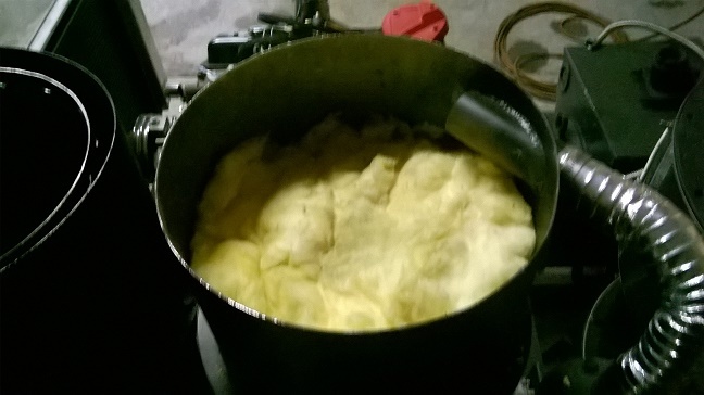
I performed the first test run on this thing and it is just awesome. The filter worked just as I had hoped, this is a type filter that the dirtier it gets the better job it will do. The only downside is you need a fireplace vac to clean it and upper filter for the condenser will need daily cleaning. It can be done manually but a vac is just a much easier and cleaner method. But this beats the full cleaning needed on older system every 600 hours. On this new system, you may never need to do this. Drawing the gas through that big tank really helps in aiding gas cooling too.
The pics are taken every 15 min or so, I ran for about 1 1/2 hours may longer didn’t really keep track of time. But this is from a virgin fill up to the end when I shut it down.


 5890.jpg" width=“648” height=“364”>