I am currently building a new revised version of the E-Series I Gasifier for our PMA power station. I think I m finnally done making changes to the E-Series gasifiers. The hearth area has changed a little to enhance fuel flow and reduce bridging. Coupled to the shaker system this new machine will flow very consistant. The standard condenosor is a little larger now and I went to pull latches for the lid.
Im hopeing to have this machine ready to flare sometime next week and then I will start the chasis for the power station. This system will be getting the advanced filter system with the Hydro Drive Cyclones and liquid cooled condensor. This system Im hoping will be cleaner and maintenance free other than changing out the water and the media from the media filter. It will come standard with a hopper shaker and grate shaker system to maintane consistant flow.
Hey MattR. sounding good.
What original engine horsepower or final kWel range is this system designed to supply for?
What will be your recommeneded fuel types?
We are starting with a 16HP Duramax engine with electric start. You can get these on Ebay for around 300 bucks. Im hopeing to harness 10 fo the 16 horsy’s for the progect and according to the PMA manufacturer I should be able to net around 7500 watts form it.
I still have to figure out the ratios for it yet. I think its going to be a little tricky. I will need to run the PMA at least 1100 rpms to get my 7500 watts. But first I will need to run the engine and find where it will run the best under that load.
The E-Series can be set up for multiple fuels. I will just need to the specified fuel requirement and I can pre set-up the machine here. The E-1 can be set up to run pellets or chips and chunks. I set the unit up with a tighter grate for pellets and choke up on the char depth. Also I lengthen the jets a bit.
Hopefully next week Ill have something to show. I have been dying to build this but have had to much on me plate and still do. But with the new help things are getting faster.
Well I can maybe help on the engine side.
Since you want this to be a gen set application you will have no actual idle or maximum power RPM requirements.
So set up your engine to operate between ~2600 to 3000 RPM in the maximum torque curve. This will give you the best woodgas power without having to modify the ignition timing. And enough RPM for good flywheel fan cooling.
On your PMA 1100 RPM is mighty slow. No not prying, I’ll wait for pictures. But no alternator/generator is 100% efficient converting shaft power to electrical watts. Whether a true 90% advanced efficient unit or a standard 40-60% efficient automotive unit this inefficiency has to be blown off as waste heat somehow. So for 7500 electrical produced watts means this unit will have to shed off a minimum of 750 watts to as high as 3000 watts of heat. Thats a lot. THIS is what kills most charging units. Will your supplier verify it can do this at that low of RPM?? It will need enough RPM to be able to cool itself or need a supplementary air or water/oil cooling system for the copper wound output coil section.
Yeah thats right its not 1100 rpms = 7500 watts. That was the min that it should be run to prevent over heating. Sorry its been a while sinse I got it and thank you for making me think of that. That probably saved me a ton of work!! Yeah that is right they did not give me data on how many RPM’s would be required to net the 7500 watts only that this is watt would be practical for 10 hp.
Hi Matt, Your new project sounds very interesting and I’m trying to relate to the numbers. Going by ear I know the more load you place on the generator the more rpms that are required. 1 HP equals 746 watts(pure number vs real operational number with inefficiencies added in)) so the 10 HP-7500 watts numbers make sense to me, .To do this in a practical manner you would have to run the gen set and load it electrically with something requiring 7500 watts( it would take 30 lf of elec base board heat to draw 7500 watts) and then measure the rpms( dot on the flywheel/laser pointer method) required to meet this load. Then I presume there is a curve that relates the rpms to HP(this may be the torque curve Steve is referring to) Adding the inefficiencies in and you might find your using much more than 10 HP to get that 7500 watts, so a 16 HP unit is not out of the question.
I’m interested because my goal is a home power unit and I needed to know this information also to size my unit. My initial thought was a 25 HP unit(wanting to produce 15 KW) so I sized my GEK to line C in the imbert chart which is capable of supplying gas for up to 30 HP. Does this make sense or am I off course here.
At any rate it sounds exciting. I’m doing some refinements on my unit so it’ll be down for a bit and purchasing a gen set that big is going to take a while to save up for.
Keep plugging away, man, sounds good. Pepe
Can you direct me to the imbert chart your are refering too please?
The 7500 is what Im hoping to get, but if I can get at least 5 than I will be happy with that. Yeah Im looking forward to seeing it complete, lots of work a head of me.
Hey Matt and Pepe
I do not wish to divert from the topic of Matts Vulcan Power Station too far. But since I did have some influence in the directions the APL Powerpallet and Victory Shop Hottwatts took with their engine and gen heads used please allow me to clarify.
Yes Pepe in the past I have said for the longest life, with the least footprint and fueling cost a slowed down speed 1800 RPM water cooled four cylinder IC engine would be the Ideal. Now having used the cast iron Kubota three cylinders DG972 engines woodgassed I can safely chop that down a cylinder. Long life meaning 20,000 to 30,000 hours between needing cylinder re-boring/re-sleeving and new pistons.
New, four or three cylinders, this is a $3,000-5,000 USD option for just the engine. These must be truck shipped adding another $300-500 USD to the cost. Full package system cost new are $10,000 - 15,000 USD.
Of course for a DYI one off system lots of local used options out there.
I had also recommended 90 degree aircooled V-twins specifically Kohler brand as in my opinion the Best minimalist DYI option.
Still $1500-3,000 USD for just the engine new. Wrapped up in a gen head package with skid and drive system $3,000 to +$5,000 USD.
This IS the route I have now personally sunk my money in for a 10,000 watt intermittent welding system (on gasoline/propane) - and a for sure min continuous duty long lived 5,000 watt woodgas fueled AC/DC power system. I will continue to recommend min 2X oversizing the engine when woodgassed fueled versus the Dino fueled rating for the engine.
Matt, I think you are going the correct route making your own engine/gen power station to supply with your gasifiers. This way you can control all of the variables with known’s to you and be able to optimized for maximun possible useable power and reliabilty.
Just throwing woodgas at a package Harbor Freight/Costco/WalMart or even a quality Honda gen-set most fella’s only able to get an actual continuos 1500-2000 watts useable per 5000 watts of unit rating. Better is possible but only with quite a bit of unit specific development.
So far I am stuck on a usable ~400 watts electrically generated per Dino fueled rated IC engine horsepower when woodgas fueled.
These DuroMax engines are a clone of current Honda’s. Honda’s themselves are know to be horsepower over rated. DuroMax users saying these power on gasoline more like a 10-12 horsepower rated B&S, Tecumseh, Evinrude engine.
So with some mixer development you should be able to get your 5,000 watts generated if your gen head is a high efficiency unit. It is good engineering to have the gen head oversized to the engine capability. This is easier for users to understand.
Hey Matt,
If you look at the top of the homepage you will see a “Resources” item. Under this will be a title “Free gasifier plans”. Click on that and at the very top is a blued link, imbertdimensionsweb.pdf. The dimension sheet is there but the extreme left column isn’t printed, but starts at “A” at the top and goes down alphabetically. I’ve downloaded the full page of imbert dimensions and my GEK type design labeled( my dimensions at top on right match except I used a slightly smaller fire tube because I had it handy-unit produces real good gas) to give you a sense of their relationship. Note the discussion on HP vs gas output required and you will see line C dimensions give me 63 cubic meters per hour which would supply enough gas for a 30 HP engine so my 25 HP choice is in the ball park here. This IS your starting point in design parameters. I choose an hourglass hearth because I was into the cone bending at the time. I also welded a flange to the bottom of my hourglass hearth so I could add a gasket for an airtight connection. If this connection isn’t airtight gas can slip by without going through the reduction zone and you end up with water and tars in the cyclone and else where down stream. Tars CANNOT be filtered out and will end up in your engine requiring a tear down and clean up of valves, etc. I would NOT do a simple drop in here as shown in the diagram for this same reason. Why, after all this work, take a chance of an “internal leak” ruining your day? I forgot to fully weld my fire tube to the flange and ended up with a mess of water and tars in my fluidyne. Then guess what- tear it apart and fix it. Much better to take the time to do it right from the get go. I learned some hard, time consuming lessons from experience or rather inexperience! A straight tube (bolted on to a flange with a rope type gasket) or other configurations can also be used. If you use a straight tube, leave 2" above the flange. Also set the top of the tube at “h” below the C/L of the nozzles. Don’t use a small grate as seen here, use a full width one for a larger char bed-important. Also my nozzle diam here is way too big as Steve pointed out. I took his advice (finally lol) and started with a 1/4" hole and it worked fine. You can always unscrew them and drill them bigger. Also missing in my design is adequate preheat for the incoming air. That is what I am retrofitting for now. Time consuming PITA. I should have listened to others advice here, too. Chris(thank you) finally drove the importance of preheat into my head. Plan for preheat before you build for best performance and you’ll save a lot of time! Check out some of my pics in the small engine section( Pepe’s first ICE) to see what I mean.
I hope I haven’t thrown too much at you but I wasted a lot of time charging to the rear(lol) and hope to help save you a bunch of time.
Regards, Pepe
I have a line on a older running (I’m told, we’ll see) Wisconsin V4 welder for cheap. I have personally completely rebuilt 4 VW engines, 2 Ford 6 cylinder engines and 2 4 cylinder International Scout engines from front to resurfaced flywheels. So the rebuild of the Wisconson won’t be a problem. Time and money are the problem, as usual, so that is way off, time wise.
You mean to tell me there is one thats been converted to Inches all this time and I just needed to add letters to it.!!! lol
Well Pete Both the E-Series I and M-Series-I can be set up to specs of A through D with a simple reduction bell change and jetting. Both utits are come stock set- for line A to run the smaller engines. Yeah according to the specs there the 10" should be capable of up to 50 hp. However, I do not think this is practical for this size of machine do to bridging caused from the higher CFM’s pulled from the unit. So I have specked the units for 25 hp max to avoid issues.
Not saying it wont though.
As for preheat, I have some problems with the concept. With respect to all that are working with this and have working machines. But this is the stance Im taking with this. I have a very broad understanding of air flow and how it is effected by temperature. Any one that has built a race engine and knows what they are doing I think will agree with me. Preheated air does carry more energy than cold air: however this energy is in the form of heat. Cold has more energy available to be converted into heat in your gasifier because it has more oxygen. Also there are some physics involed concerning the deferential of the energy conversion from the air tranfering from one state to the other. the larger to more bang. When you are playing with this the dementions in that chart no longer apply. Every thing changes when the air is heated. The volocities change, volume changes there for you jets need to change.
I have built preheat systems and in my experience it made no difference. The vulcans are working very well with out it and if I can keep it simple that is ussually the best policy.
Is there a thread on preheat? This is something that Id like to explore more and also I think it needs to be fullly explained for any one that would like to experiment with it.
hi matt
I understand what you mean about the preheat on a race engine hot air is the kiss of death but from what little i have learned about gasification it would be easy to get ample 02 to the flame but if you went to far it would just be a reall hot wood stove I think the fact that you want as much heat with as little 02 as possible is where the preheat comes in without preheat you have to use more energy to get the air up to cumbustion temp thus more air and less left for gas i’m in the process of building a small wk to mimic my china hybrid i will let you know how it turns out as i have the hybrid documented pretty well
First i have to fix my lotos plasma cutter just got the mother board $80.00 so we will see
It’s a gimic send it back for waranty and pay $89.00 freight or pay $80.00 for the board and fix it yourself
If it barfs anymore it will be land fill i don’t havemuch time to play and i’m not going to waste it playing with junk
It may have just been a freak We will see
Thanks
Tom
Actually a pretty fair explanation ThomasM.
And a very good observation MattR that once you do go with extreme primary air in pre-heating the Imbert tables especially as related to jetting go by-by.
I have seen all three ways work now: Doug Williams/Fluidyne NO Preheat - cold air straight in; moderated preheat as in Imberts, early GEK’s and I assume yours Matt; and now radical air pre-heating as in Larry Dobson’s, later Victory works and now the Keith system. They all work but do require different geometry basis.
This pre heat or not pre heat got jawboned to death over on the Y. Woodgas groups in the past to no avail.
The only place here this is talked about Matt is on the Premium side as related to Mr Waynes design.
In the order I have listed you will have increasingly difficult construction and much more possibility of sudden material overheat destruction. Third stage stuff you either have to use much more expensive materials like SS and Inconals, fragile ceramics or a high labor hour complex constructed design to cope with the elevated temperatures/heats. Radical pre-heating your wood fuel economy of usage will decrease; you can use much wetter fuel stocks and your BTU/joules energy potential of your produced gas will go up higher. A denser more fuel molecule packed gas.
Heres why: because we use atmospheric air. It is 79% diluted with inert nitrogen. The less you need to put in the less nitrogen carry over into the produced gas. This carried through nitrogen will displace out fuel gases and engine needed air drawn into the engine cylinder. Just as important with radical pre-heating, once you do have a huge surplus of heat to work with then you can actually be heat disassociating a higher % of the fuel and inlet air H2O moistures. The free up O’s then available then means you need even less gasifier inletted air with it’s nitrogen. Many radical pre-heated (and insulated) systems once up to operating temperatures with a good “wet” fuel inlet less than half the air as the other system.
Not trying to convert you MattR. Use what you got. It will work mighty fine to get systems out there, affordable, understandable and in daily useage. Big mistake to keep chasing those Angels and cramming them back onto that pin head. Leave that to brainiacs with more time than sense of time.
Again just stick with a 2X IC engine oversizing to compensate.
On your reasurch side really ,really look into the hot rod automotive fired ceramic exhaust powered and paints. John Blount reported real good hearth core success.
Hi Matt, Check out the Learn heading at the top of the home page and under that is a title, “Basics of woodgas” which explains the process.
Hope this helps.
Pepe
Richard, I have machines all over the world bro. Im well beyond the basics lol.
Like I said I have a very broad understanding of air flow and the effect of temperature that can bring along the tranfer of energy form one state another. This does not come from my experience in gasification. It come from my work experience and back ground. Im not saying this doesnt work in the least. What Im saying is as a manufacturer trying build and sell high quality machinery at an affordable cost…KISS!!!
LOL
Yes Later I will be playing with preheat and a more advanced jetting system like I was working on earlier this year. But I have a road I must take and I have few miles to go before I get there.
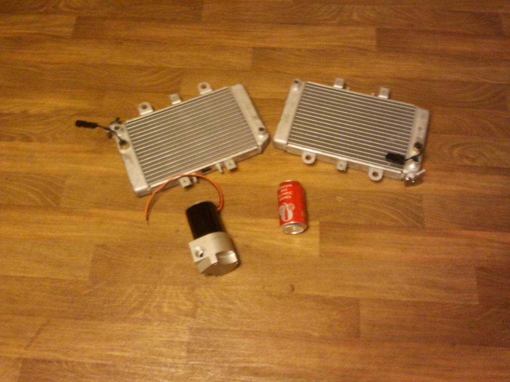
OK I have some parts that came in, this is for the liquid cooled condensor and hydro clones. I have a Jegs race pump and some radiators I ordered. I have two rediators one is for the Tractor conversion and the other is for the power station.
Im going to order another water pump after I do some testing with this Jegs pump for the hydroclones. I think I have a design figured out. Im thinking of haveing my cyclones and condensor share a single tank. Each component will have its own partition to isolate itself, however there will be a pasage at the bottom of the partions so they can all share the tank and the condensate levels will equal out. I dont know if this will work I hope it does, I want this to be a compact unit it will have a 12 x 18 foot print. I am planning on using the water in the condensate to power the hydroclones. Im not sure if Im going to worry aobut cooling it. I think if I run the condensate through one of those radiators it will clog. I may either use a transcooler or I may build a circuit in the condensor to run the condensate throug to cool it.
The condensor is going to use anti freeze for cooling. It will have a cooling tube design but not a bunch of tubes in a vesel with anti freeze running through it. I am going to build a jacket for each cooling tube, this will greatly increase the flow and I can still pass air though the tubes for further cooling. Im hoping this design will be more eficient.
I ordered a Jeep windshield wiper motor for the automated grate system still waiting for it to arive. Aslo on order are the controlls, speed controlls, timers etc. Ill post some pics of the motor and PMA in the next thread I need to go and take some pics of first.
Here is the motor and PMA Im going to use. Im thinking of just building a platform onto the excisting base for the E-1 gasifier. This way the motor will constintally vibrate the gasser and if excisting customers want to upgrade to this it would be a simple conversion.
The last pic is the gasifier Im going to use for this project LOL
matt, how are you figuring what size radiators to use, im pretty sure two car radiators will work for a very large application, but im still working out how to make the heat exchanger surface area comparable to the radiators ability to transfer heat, im thinking about what system would be lighter, a regular style cooler or a compact heat exchanger with water pump and fans, i would assume the later would be lighter and more effective
Hi Brent
I use water cooling (see my post, flare at 1/2 pound per min in general discussion) I mount my radiator
high and do not need a pump. At more than 1/2pound pound of wood per min you will need a fan.
Im just basing it on my excisting air cooled condensors. Plus those radiators fit the budget. So I hope they work. If I end up needing more cooling then Im going to cool the condesate in a seperate system. Part of the job of the hydro clones is to add further cooling to the gas. The hydro clones will use the condesate as the driving fluid. My air cooled condensors do an ok job by the time the gas makes it though the condensor and the mixxer its down to about 20* higher than ambient on moderate days 70*f. The cendenosor I offer now can be added onto as well. For this liquid cooled set up the intent is to cool the gas as fast as possible before it reaches the last hydro clone. I want to do this in a smaller package that will be much less maintenance and hopefully will make cleaner gas.
Building the condensor light wieght and compact is part of my criteria as well. This is why I decided to go with this design of having my cooling tubes jacketed individually. (tube inside a tube) So I will be able to run coolant though the jacketed tubes and also blow air through to cool the outside tubes. This system will be easy to perform maintenance on as well. I have the material orderd so Im hoping to get a start on it this thing this weekend.
Yeah Dave, thanks for the post that makes me feel more confident it will work. Nice set up BTW