I’m trying to figure out how to make a throttle pedal for my “new” blacksmithing “forge blower” (AKA “salvaged NG furnace blower”). Someone suggested I use a speed pedal from a sewing machine as my controller. That would give me hands-free control. Also, my blower would shut-off when I took my foot off to pound on my irons, saving fuel (wood charcoal).
I got a new blower (to replace the one I dropped and broke) from an HVAC guy, and a sewing machine pedal from the sewing machine repair shop. Now I just need to figure out what to do next!
My guts are telling me to wire the controller into the middle of one of the blower power wires. Both blower wires are the same, and the built-in plug is even made to be reversible so I don’t think it would matter which wire I used, correct? The diagram on the blower (pictures soon) says:
“Blk ---- Line
Blk ---- Line
Grn/Yel ---- Grd”
My thinking is that I would snip “Line B1 (Blower Wire 1)”, connect the “Blower side” to "Line C1 (Controller Wire 1), and “Power Plug side” of B1 to Line C2 (Other wire from Controller). “Line B2 (Blower Wire 2)” would be uncut and run straight from the blower motor to the power plug. Does this sound right?
I included a picture of the “guts” of the controller pedal incase people can “read” them and warn me of possible problems.
I may not have the precise answer you are looking for but maybe can help you to clarify the Inputs to this project so someone else can answer for the Output you are looking for.
Your blower motor is very clearly marked 240 volts alternating current for 60 cycles. It is not going to like being lower 115/120 AC common North American wall outlet ran. (complicated for the detail explain)
Looks like your speed contoller is marked for a power input of only 115-120 volts alternating current 50 or 60 cycles??
My earlier furnace blower were brushless AC power and one speed only. On-Off only. They DID have multiple OUT wiring to allow for external connecting to one of a slower speed or higher speed at any one time. Done wire different internal windings path circuits. Had FIVE wires coming out for this tow speed only changeability. You do not show this - only FOUR wires out??
Newer replacement furnace system I paid more for a soft starting blower motor with ramping up and down for stepless smooth variable speed capability stopping with a speed ramping down to off.
Means my newer blower motor WILL like in a sewing machine be a universal alternating current or direct current brush type motor. These give this easy long life high torque varible speed controlled capabilty. ONLY Two wires out.
The furnace controller system then controlling the motor speed by varying the supplied voltage as a converted direct current input to this motoer. OR, more likely with modern electronics power circut capabilty actually for variably timed pulses turning off and on the fixed DC voltage to the motor. Pulse Width Modulating.
Looks like you have a NO internal brushes not variable speed motor from the picture. Any contact brushes in there contacting up against a rotating copper round commutator??
Your controller INPUT look to only be for lower AC voltage - not for the Higher AC motor marked voltage. (again complicated “phasing” explain to this)
You controller I believe only WILL Output an internally converted direct current voltage motor supply from an internally specified 100-120 volt alternating current Input.
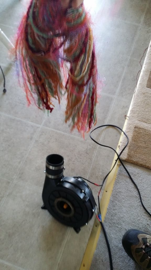
The blower “should” be 115V (furnace guy said it was) and I read it as saying “V~115 Hz:60 A0.7 RPM 3450” on the left side of the label under the FASCO icon.
I do see “4 MFD/250 VAC” bottom right, under the “Connection Diagram”. I think this is a confusing and poorly worded label.
The label shows 5 wires, but only 3 come out: 2 black “Lines” and one green/yellow ground. The other 2 “browns” I believe are used internally for over-load protection.
I tried to google the part number to see what the 4MFD/250 VAC means but no joy. They are listed as 115VAC power. www.boatandrvaccessories.com/rr119.html They are also listed at 150-250$ brand new. Holy crap. The furnace my blower came from was used for less than a year (illegal/uncertified install in a rental unit but works fine).
I do know that the motor does not want to be slowed down, but will. I tried a lighting “dimmer switch” on my previous blower and could get the motor to spin about 1/2 speed or slower but the motor got hot faster.
Sorry, I should have been more accurate in my initial wording. I don’t actually need the pedal for speed control, that will be handled by an up-stream ball valve set at the air flow I want. The pedal is more of an On/Off “momentary” switch for the blower. While I’m heating my irons, it’s “pedel to the… gravel”, but as soon as my work piece is up to temp, I pull it from the fire and turn to my anvil, when I do, my foot comes off the pedel and the blower stops.
On a side note, I do remember the guy telling me that the blower is sucking the HOT air directly off the furnace guts. I know a lot of heat is lost in the ducting, but does anyone know how hot the gas RIGHT at the furance would be? It uses a double-sticky foam gasket tape so probably not that hot, by our standards, but I’d think IF we could use these for woodgas blowers, we’d put them after the filter anyways. Would these be good choices for stationary guys (or with an inverter for mobiles) for suction blowers?
Ach. That makes it easy then.
Set aside the sewing machine foot speed controller for a future project that will have a brush type universal brushes type motor.
Want you want is a simple on-off drill press foot switch.
New. Harbor Freight. Others.
Used. Lot of fair weather garage sales now.
For an actual restricted hearth woodgasifier these squirrel cage blowers will not generally pressure suck or blow good enough. They are for low pressure high air volume use.
Inline fan blade blowers ussually not good for enough pressure making either. Can be made to work ganged boosted as WayneK does.
For real restricted woodgas system flow pressure boosting you really do need to favor the turbine impeller type. These can be engineered designed for different ranges of pressure versus flow versus input power needs. These also can be series ganged up for increased pressure differential boosting. See a picture of that on APL’s GEK site. Or parallel installed for increased system flow capacity.
Ha! Then of course exceptions like VesaM’s made up system blowers using powerful Eurocar 12 vdc blower motors and his own purpose made up bladed pusher “fan”. He blows his system to hot operating - helps distribute the push pumped squirted in Finn-way of using non-freezing sensitive spirits lighting-up fluids. Then the gasifier system is irresistibly engine hard pistons sucked, drawing hearth air in past the non-powered “fan” blades through the same pathway. No change over air valving needed. No hot producer gases passing through the “blower”. Air flow cooled. Elegance in design is the hardest to achieve.
“Any damn fool can make things over complicated and expensive! Take a REAL Engineer to make things simple elegant and effective!” Not my quote. A common field serviceman’s curse lament; and grudging compliment.
Well, for right now, I have what I have and can easily chop’n’splice something better in later when I can get them. “The best thing to use is what you already have.” -Wayne Keith
I change-jar scrounged enough for a pack of wire butt-splice joints and now have a working forge blower with “momentary-ish” for control which was my goal.
:edit: Picture 1: no foot, no draft.
Picture 2. Foot on, draft on.
The e-motor on your picture is a 115 Volt 60Hz AC motor ( left on the picture )
The 2 brown wires are for a capacitor 4 micro farad 250Volt AC ( right side of the picture )
The RPM of this e-motor “can” be modified with a frequency regulator but the minimal speed needed for the cooling ( copper windings ) should be not underpassed
If you have only on and off, you will want to be able to control the actual force of the air for several reasons. Many guys insert a butterfly valve or air gate in the air stream for this purpose.
For instance, you need only a small air stream when starting the fire. You need a larger blast when you are heating big things. You need to be able to turn the blast down as you approach forge welding temperatures.
Of course the “ultimate” foot control is when you have a foot powered blower. When you quit pumping, no air.
Pete: I do have a 1" Ball-Valve upstream of the blower so that I can easily set my flow control, as needed.
When I started out, I did consider using foot bellows (once I had the basics down) for the control factor, as well as “authenticity”. Then I remembered that my knees are already falling apart and my balance isn’t very good. I figured teetering precariously on 1 foot next to a hot fire and ~2,200F (1,200C) metal might not be in my best interests.