You were not alone on this design. It took me awhile to figure it out. It’s so simple it hurts. Makes me want to build one for my lawn mower tractor.
Bob
Tom, it might be my turn now! In my old age I forgot to install the wire spacers and it ran just fine. So, after it is running the engine I just put the pan on spring tight. There must be a space, just too small for easy notice. At shutdown, I just shut the engine off, that is all.
Hi jeff
do you have an explanation? why do you think the engine works better with this restriction?
can the reactor, in negative pressure, produce a better gas? a bit like a gasifier with a small nozzle vs a big nozzle (high speed vs slow speed of the air enter the gasifier)

Hi There:
Thank’s Jeff, Al, Tom and Terry for your commentas and suggestions.
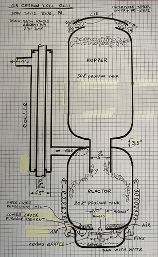
I revised the drawing. Please check it out.
Hope this is it.
This will be the Revision #1 of the “Air carbon fuel cell” drawing-Jan 2018. By Jeff Davis.
B.R.
Eddy Ramos (Argentina).
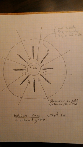
Ok got it, thanks. Now the next question is, what size is the air gap? Is it variable?
I need to remind that it seems to run as well without the spacer as it does with the spacer. I can not say, for sure, that it runs better without the space. What I can say is that I thought that it seemed to be a nice run and then I noticed that there was no air space.
I put a lot of effort to reduce the restriction in this system. Even the 2" grate hole is an effort to reduce vacuum. So, what a surprise to find out that it ran just as well capped up! Possibly vacuum concentrated at the point of reaction does help or possible Eddy Ramos thought that the air becomes more preheated by clinging to the hot tank. I do not know.
Yes, it looks good ! ! !
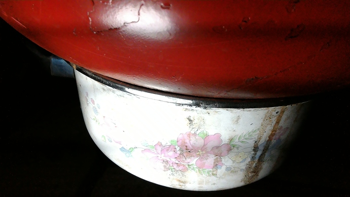
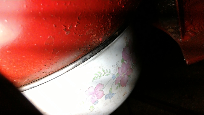
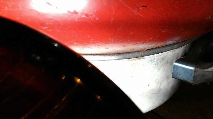
Saturday I’ll dig up a feeler gauge. We are looking at two as pressed surfaces touching, one painted.
This spot is ~ 0.020 inch.
This spot is ~ 0.010 inch.
And these spots (remaining) are too small for me to measure.
What if it has to do with steam. Under vacuum more steam might be generated in the pan. If so could this also be self regulating? More pull from the engine the higher the vacuum and more steam is generated. I do not know. This spring I should find a Pyrex bowl so we can see inside. Can I buy a bottle of coloured air to watch the air flow???
If you have a vacuum on the inside edge of the bowl and air is moving between the rounded edges with an opening in the unsealed metal edge. The velocity of air moving between the edges will open it even more until the vaccum drops and velocity lowers keeping it open. The same thing as air passing over a wing effect giving it a lifting force. Spring tension and bowl weight are going to be factors in this.
Bob
Hi Everybody.
I have started a new topic with a collections of my drawings, part list, spec’s sheet, and/or operations procedures, it is call: “Drawings of charcoal gasifiers for vehicles”. In this new topic is included the work I have done for this topic. Thank’s Jeff.
Hi Bob!
24.5.2018
You are totally missing the pan diameter!
The pan diameter tells the “piston diameter” of the pan. The pan bottom surface
is = the piston surface.
Piston surface X pressure difference (outer/inner) makes the pushing force upward.
The pan-edge dynamics do not contradict the “piston pressure” generated
by pressure differernce in/out - side the pan…
Oh the light just came on, thanks Max. I miss it again, but it is great to have people like you help us out.
Bob
You know fellows for those of you wanting to go-more-discreet hiding in plain sight; or upgrade the perception from ho-hum old wood you could adopt Jeff Davis’s terminology.
“I’ve been working some more on my Air-Carbon-Fuel-Cell.”
“How is your AC-FC coming along?”
In-the-know talking. Need-to-know talking.
S.U.
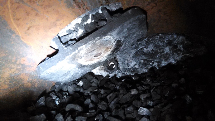
This is a photo of the oxidation plate, after a couple runs. This is the producer that is on the front of my log hauler (small red machine).
Jeff,
I’ve been in Rwanda and missed this picture when first posted. Can you help me get oriented? I can’t tell which way is up, down and sideways. I’m guessing that the picture is upside down and we are looking out through the lighting port?
Hi Bruce,
Open the fill lid and shovel down, through the charcoal, until the air inlet is found. Like a nozzle but a baby Pedrick instead.
One mistake is that it should have protruded further into the produce because the out side of the producer gets hot enough to soften the plastic filter that is close to that hot spot.
The big out side pipe I would make a larger diameter. More heat sink and help preheat the water vapor and air. Tha water drips into this pipe that is welded to the back of the oxidation plate. I think this pipe will be called the outer pipe. This is the pipe with the elbow screwed to it.
The inner pipe is shorter in length. Diameter is just larger than the hole in the oxidation plate. The inner pipe is inside the outer pipe. It helps to cool the oxidation plate and preheat the steam/air. It might also focus the air stream.
However, this is just talk at this point. Ask me in two years, how is it holding up?
Hi JeffD,
Perhaps explain the relitivly unknown, Pedrick “hot-plate” system versus all of the in-free-surrounding-space producers.
Regards
S.U.
Ha, l used a similar nozzle design on my charcoal powered moped way back. Didnt work for me as the maseve plate sinked heat too much for the litle 50cc engine gasifier. But l bet it wuld for a larger engine.
I stoped looking for a intense heat proof material long ago, its the mass l swear on. Cheap and reliable.
SteveU, there is the nozzle design that we all know. Minimal amount of material that is exposed to a large sized hot spot. The lonely soldier fighting the forest fire all by himself. Ouch! Soon to tire…
The fire plate, I renamed “oxidation plate”, is a large plate, mass, that has a better chance to face the fire. A hole in the wall, so to speak. Now there is an army to fight the forest fire. Heat sink. Heat dissipation. Of course armies can also loose the war.
I choose the word soldier because they are common people like the material I like to work with.
Pederick gave a lifetime warranty for the fire plates used in his producers. Of course they were heavy. So heavy that the weight of one of his gas producers broke the rear axle of a politicians fancy car or so the story was told.
Without getting to detailed on a public forum, the doctors say I’m running out of time. so here is my next light weight version of my gas producer. As SteveU would say, old men should pass their experience on to others. This forum is my only way to do that. Not sure if I have much to pass on but I will try and maybe it will also help me.
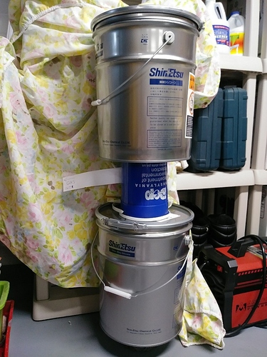
Made out of two wonderful metal 5 gallon buckets that were gifted to me! Made in Japan, top quality. between the two buckets will be two coaxial tubes that I want to roll out of scrap sheet metal (represented by the blue plastic container). The inner will allow the charcoal to pass from the top fuel hopper bucket to the bottom partial reactor bucket chamber. The outer tube will pass the gas out thus preheating the incoming charcoal and cooling the out going gas. The outlet pipe is represented by the white paper.
Below the bottom bucket will be the oxidation and grate zone. That is the space between the floor and bottom bucket. The can that the bottom bucket is setting on can not be seen in the photo.
This is just stacked up with plastic cans and stuff to give a vague idea of the design.
It would be nice to build two of them before Argos so I could ship one of them to the show and donate it to somebody like BruceS but I have a lot of doubt that that will happen in time.
I wanted to buy a small slip roll for these projects but I doubt that it would bring much at an auction when I’m gone and it would be just a waste. Maybe I can roll the sheet metal by hand for a few builds.
I have a new charcoal grinder in mind and a wood fired space heater but I doubt that I will get to the heater. I do really want to build the new grinder.
Oh well, this new turn in the road allows more time to work with my Raspberry Pi 3 + and re-learn Python. 
Cheers and let me know your thoughts!!
