Thanks Steve. This comment section is wonky, we never properly developed it. Hence the dev.driveonwood links.
I would like to contribute to this effort. I can provide design work, SolidWorks. I can make aluminum castings. I can do very simple machining. I can make (very simple) printed circuit boards. I made a very simple and low cast actuator: muscle wire spring, that might be useful. https://www.youtube.com/watch?v=O8eHD_lBpHM
Rindert
hi is their any one out there who can write code that can make a program to make a motor controller (PCM) that will let a person mix the wood gas or go to gas or propane etc. and change the perimeter to whatever you want to use plus change the timing etc. it would change the way we see fuel interaction. We could start with gas when it warms up switch to wood gas or any gasous fuel then when we were ready to sut down switch bas to gasoline to wash of the valves
A reasonable basis for such a device already does exist - check out Wide Band Electronic Mixer Control Tutorial, shared by @Matt
It’s pretty flexible and is a reasonable platform for doing what you wish, straightforward enough to integrate with various standard PLCs, etc. Several of us have built copies or derivatives.
Ive ordered a 3 wire electronic controlled ball valve to play with. It uses I gear drive system with a brushed motor. Im thinking the code could be changed to output pwn signals to control it. Since this is not reliant on position have a servo really is not necessary.
I believe the Valve has two wire to control, direction and then the third I think is a shared ground. They come with limit switches so power cut after reaching the limits in either direction. So you would need to use two outputs, one for each direction. Then map the PWM to the rich or lean range sets from the O2 sensor input.
if you had a reostat to give it a positon sense it could produce a perfect gas carb hook it to a lembra probe??
Let me introduce my simple version of an automatic gas mixer.
The main goal of design: low power consumption.
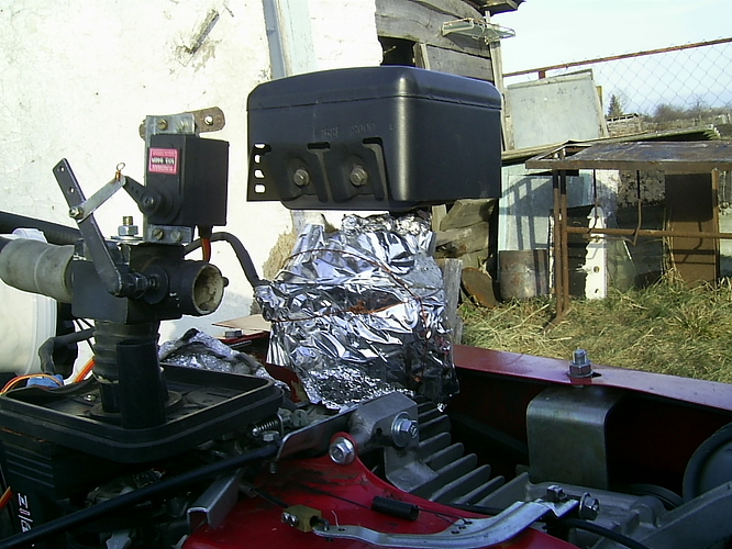
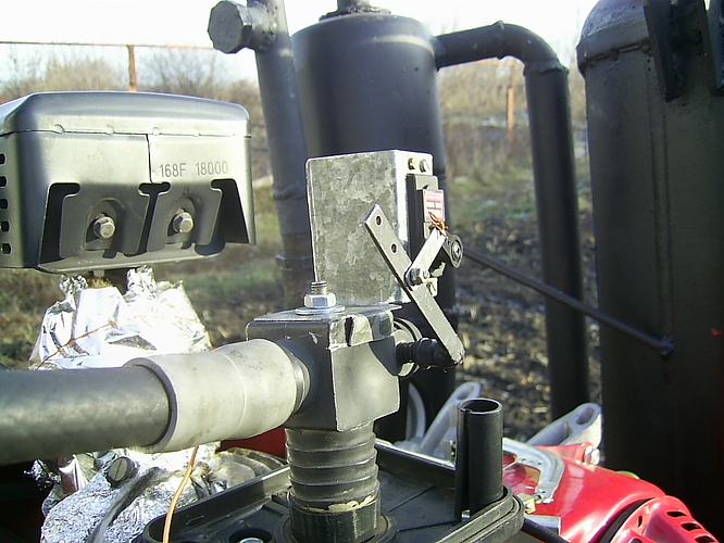
Designed for motoblock with engine LIFAN 168F-2 (clone Honda GX200).
motoblock - in Russian мотоблок, possible translation: mini motor cultivator, walk-behind tractor
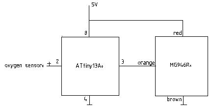
All automatic control consists of three elements (we do not consider the power source):
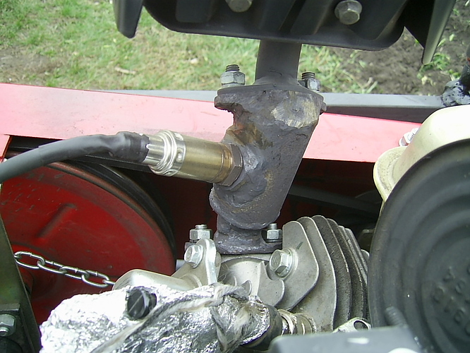
- oxygen sensor (lambda sensor)
- servomotor MG946R;
- microcontroller ATtiny13A.
Electrical wiring diagram

The program for the microcontroller ATtiny13A.
/*
- Настроен под сервопривод MG 946R
*/
#define F_CPU 1240000UL // укажем компилятору частоту ЦПУ
#include <avr/io.h> // Подключим файл io.h
#include <util/delay.h> // Подключим файл delay.h
void adc_ini()
{
#define PB4_BIT (1 << PB4) // Определяем порт вывода
ADMUX |= (1 << REFS0); // Опорного напряжения АЦП 1,1В
ADMUX |= (1 << ADLAR); // Результат преобразования выравнивается по левой границе 16 разрядного слова ADCH+ADCL
ADMUX |= (1 << MUX1) | (1 << MUX0); // Выбор порта ADC3
ADCSRA |= (1 << ADEN); // Чтобы АЦП было возможным
ADCSRA |= (1 << ADPS1) | (1 << ADPS0); // Задает частоту преобразования, 1200000/8=150кГц
DIDR0 |= (1 << ADC0D) | (1 << ADC2D) | (1 << ADC3D) | (1 << ADC1D); // Выводы не используемы на цифровой ввод отключаем
}
unsigned char adc_read ()
{
unsigned char result;
// Запуск АЦП
ADCSRA |= (1 << ADSC);

// Ожидание окончания преобразования
while ( ADCSRA & (1<<ADSC) ) { ; }

//result = (ADCH<<8) | ADCL; Формирование 10-ти разрядного результата АЦП
result = ADCH;
return result;
}
int main()
{
unsigned int rst;
adc_ini();
DDRB |= PB4_BIT;
	while (1)
	{
			rst = adc_read ();

			if (rst > 198) // Соответсвует 0,85 В.
			{
				PORTB |= PB4_BIT; // HIGH
				_delay_us(720);
				PORTB &= ~PB4_BIT; // LOW
			}

			if (rst < 70)  // Соответсвует 0,3 В.
			{
				PORTB |= PB4_BIT; // HIGH
				_delay_us(3000);
				PORTB &= ~PB4_BIT; // LOW
			}


		_delay_ms(800);		// Период повторения одиночных импульсов, опроса АЦП

	}
}
well i will be. You are a way ahead of were i thought you were with this controler you could hook it up to a car ,tractor, or any motor and run it like normal. very effective. like they say as and you will get. you do run the gas through the carb hook it on at breather. thanks for the info i will chec into it more,
No need for a reostat, from the logic controller you can use PWM to simulate it. You would need a motor control board, that would convert the 5 volt to 12 PWM. that have built in MOSfets.
I was thinking about this valve last night, and a simple method to control it. Is to use a mosfet to sink the circuit. So you are basically pulsing the single shared ground wire. Then to control direction use a single relay with a normally open and normally closed option. So basically if the relay coil is off the the NC leg will be power and then if you supply power to the relay coil then the other leg will get power. Use the ground to control speed or simply open the circuit to completely stop it.
on a car controler the voltage is 5 volts. cut down from 12 a chip which is the same thing for a usb charger takes 12 volts output is 5 just a chip looks like a rectifier yes the voltage is pulsed and on the neg. side if you have a position senser the computer would know the valve position at all times that is why there is position sensers on the axis of our cnc machines because after 3 or 4 hours the control may go out of wack. the throttle control valve from from a fly be wire car wold work and they all have them now maybe just go to the wreaking yard and salvage one if you have a fieind there probly no cost… some of the fuel body injectors have the fuel injector in the body then the fuel injector is on the outside of the syn gas flow
The stock engine set up will not work for mixing wood gas. Regardless of fuel system the throttle plate is your throttle and only controls how much Wood gas / air mix is allowed into the engine.
You have to use a separate mixer system that is external to the throttle body. Then this combined air fuel mix then enters the throttle body pre throttle plate.
The valve on the remote mixer to control this;; the position is irrelevant as this is not a static system. That is sort of the point of the auto mixer as it will self adjust to any position until the controller is satisfied and tells it to stop moving. The controls are not position driven, in my code the direction along with the speed of movement is controlled via the Lamba input from the O2 sensor. If the mix falls one way or the other, just slightly the motor moves very slow until it reaches the “Happy Zone” If things go way out of wack then the controller instructs the motor to move much faster but will ramp down as reading get closer to the Happy Zone.
okay so the valve if lean will open till it finds a sweet spot if it is rich the valve turns the other way until it reaches the sweet spot?? this has to be on the inlet side of the throttle valve. okay then a throttle body will not do. you need a fuel injector in the side of the intake after the throttle valve and the gas inlet before the throttle valve unless you use a carb then both gas and gasoline needs to be before the throttle plate,. i think i see your point now… Can the oxygen senser tell the difference from gas or wood gas or is it just exhaust gas oxygen it senses
The oxygen sensor simply detects oxygen levels in the exhaust and can do this regardless of fuel type. Ethanol, methanol, diesel, kerosene, gasoline. lp ng WG etc. You get the point. However, for every fuel there is a specific scale and the stoichiometric air–fuel mixture for each fuel is different. For wood gas the gasoline scale guages and lamba 5 volt ref signal work just fine. Generally the gauge will show a very lean condition for wood gas. But this is not the case as its in the gasoline scale.
@Chris and @gasman have come up with an “automixer”. Wouldn’t it make sense to just rig an O2 sensor to the bypass via amplifier, power supply, & etc?
Those systems work on pressure equalizing I believe. So they are not using any reference from oxygen levels of the exhaust.
Adding this in would only make the electronic system more complicated and is not necessary.
To some this may seem complicated; however, once you get past the intimidation of the electrics its a rather simple system. If you use an O2 sensor you are going to need a device to interpret it and then set of working parameters to make use of your outputs to what ever you are trying to control. A simple servo is very easy to control with the micro controllers. The latest code is pretty bullet proof and is very precise. It would be dificult to replicate that with other devices.
The new valve Im looking at, my hopes are it will be a more solid valve ready to be used off the shelf. I should be able to mod the code to make it work. Might be even simpler than the servo code. All you guys have to learn is how to copy the code and paste into the Arduino IDE. If you can use word pad, you can use the Arduino software, it is very easy to use. Once you have the code pasted you save it and then connect a board to your pc and upload the code. There maybe some set up but we here can help you with that or forward you to a youtube video that will explain it in a few minutes.
The current state of the art as it applies to automixers is that the operator controls a bypass valve using a cable, based on AFR gauge reading. So simple, at first I didn’t want to touch it.
But on second thought It would be useful if an engine - gasifier system needed to run unattended for an extended period of time, so that an automated grate shaker or other factors that might affect gas quality. What I propose would replace the operators eye and hand with electrical components.
thanks ill need some time to process the info,
Not sure Im following you a 100% , but my mixer does just that. It will automatically adjust the mixture on its own. On a stationary system, bridging and grate flows are very predictable. I simply time the machines and adjust the timers in the code and it works quite reliable. I am however going to add two more sensor on all next generation systems. One will actually use a MAP sensor to detect the pressure of the gasifier. (So those looking for cheap inexpensive 5 Volt pressure sensor there you go, thats what a MAP sensor is) The second will be a temp probe at the restriction of the gasifier. This will just read the outside, I dont need to know core temps, I just need to see good operating temp.
So the pressure sensor will actuate the grate when needed and the temp probe will actuate the hopper agitator when needed. That could later control air intake input as well. But small steps for now.
Hi, Rindert!
19.1.2019
What you describe is the normal manual system; the sentence is correct if you omit the word “automixer”!
A mechanical automixer is not affected by an operator in any way.
It feels the underpressure in the arriving gasline and keeps the arriving airpressure at the same level.
This happens with a comparing membrane; one side is connected to the arriving gas-line, the other side is connected to the arriving air-line.
So the air-side is “self-regulating” itself with a membrane-driven flap in the airline to the same level as the arriving gasline.
Both “branches” go to their corresponding twin-flaps in the twin-throat carburetor-body.
50 : 50 volume mix is thus achieved. Both twin-flaps have the same geometry, exact!
There is a difference between manual and automatic adjustment!
Max
Chris has described how to build it, and Bob has managed it further.


