All the best goes to the Husbandman: a digital dry crankcase for an agricultural truck.
As you know, a husbandman grows food for his family, so he doesn’t have time to do major engine repairs during harvest and he doesn’t want to lose income paying for spare parts and these repairs just because some spring of the pressure reducing valve burst in the engine lubrication system, or the oil pump jammed, and several dozen mighty steel horses died in just one minute of dry operation… As you know, a farmer grows food for his family, so he doesn’t have time to do major engine repairs during the winter and lose income paying for spare parts and these repairs, just because some spring of the pressure reducing valve burst in the engine lubrication system, or the oil pump jammed, and a bunch of mighty steel horses caught fire in a minute of work on dry…
And ourVolga's engine had this very spring crumble in my hands after two clicks on it. And the hexagon of the oil pump drive was broken off inside the drive gear of the ignition distributor, although it still continued to turn the pump. And no diagnostics of such an important motor system !
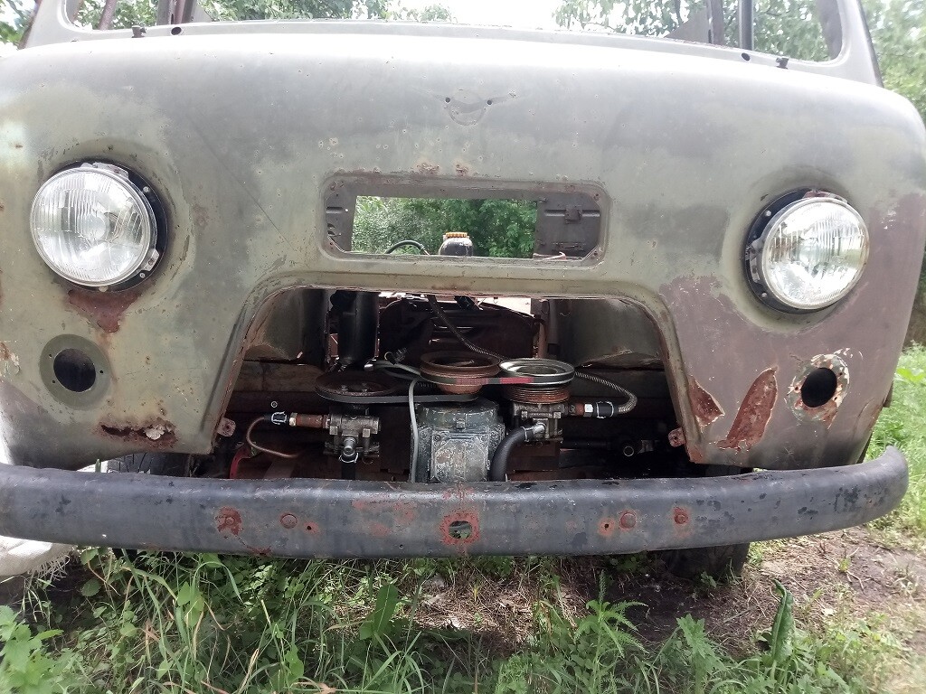
We will not put up with such shortcomings, and therefore we will go a different way. So, the entire oil path in the digital oil system looks like thi s:
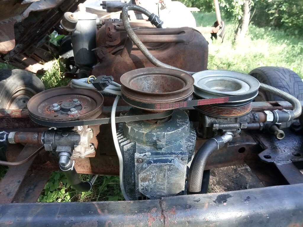
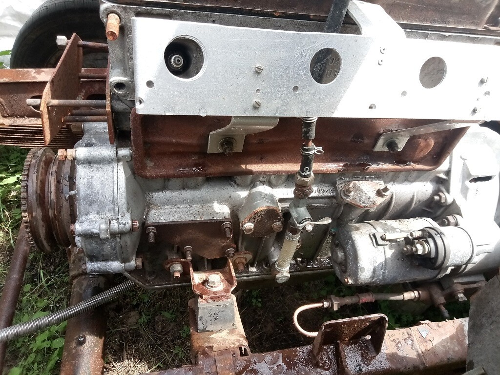
- oil with crankcase gases is sucked out of the pan with high volumetric capacity by the first stage of the oil station.
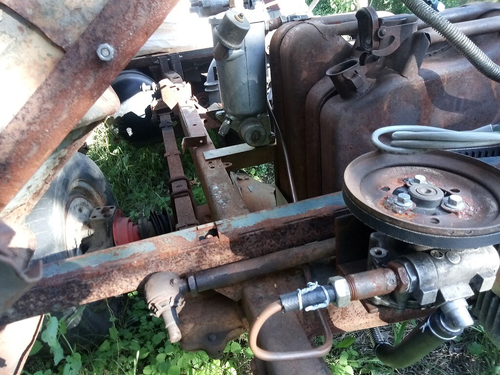
2) from the outlet of the first stage (pump on the right), oil with gases enters the oil tank of the engine lubrication system (the same tank is already installed next for the hydraulic oi l ).
3) oil flows from the bottom of the tank to the second section of the oil station (pump on the left). Due to other pulleys, it operates at a lower speed, which allows it to maintain the necessary pressure in the engine oil c h a nn e ls.
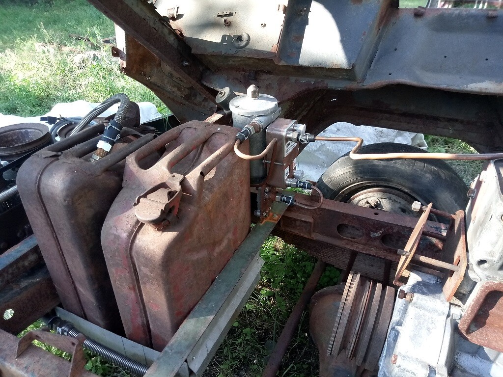
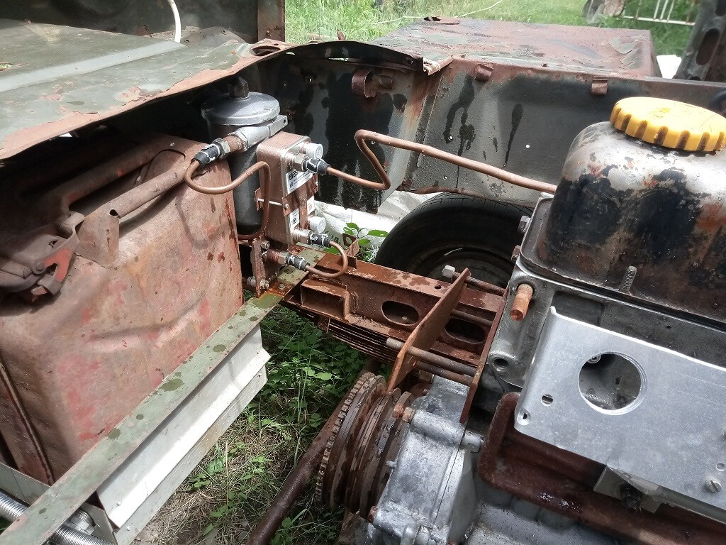
4) from the outlet of the second stage, the oil enters the improved filter – the bypass valve, which previously allowed it to bypass the filter element, is blocked in it. This outrage has now been stopped forever by new digital solutions. Two pressure sensors are installed in the filter housing at once: before and after the filter. By the difference in their pressures, the lubrication system can now determine whether the filter is installed correctly (its sealing rubber bands, as well as whether it is there at all), how clogged it is, at low oil temperature, the system will not now try to tear the filter, but will reduce of the volumetric capacity oil supply to stabilize the delta pressure before and after the filter, while the oil will not accept the working vi sc o s it y.
5) after the filter, the oil enters a very beautiful and compact water heat exchanger to stabilize the oil temperature: if it is cold, it will be warmed up by the heat of the coolant, and if it is heated above normal, it will cool down to its operating temperature to evaporate moisture inevitably entering the oil from the cra n k ca s e gases.
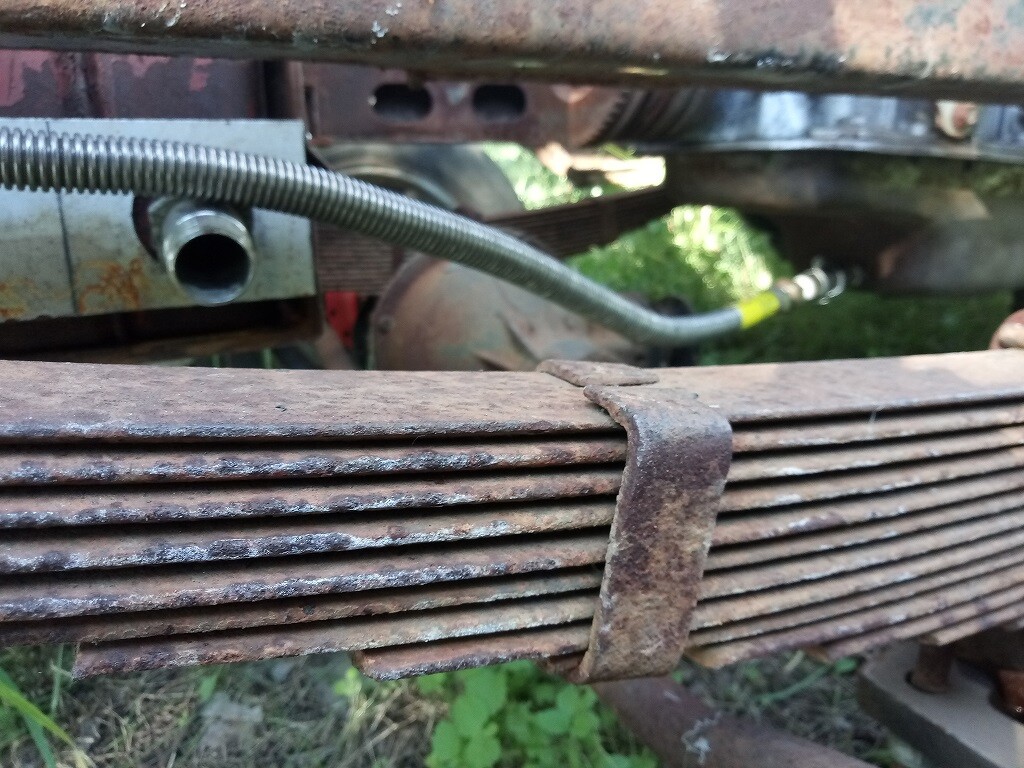
6) from the heat exchanger, oil should flow into the channels of the engine lubrication system, but since the cylinder head is not yet tightened as it should, then for tests of the lubrication system, oil flows back into the pan through the tap (to create various test modes) through the previously standard hole in the cylinder block (later oil will be drained from the sump of the a i r compressor).
(there are no photos yet)
7) all this is controlled by a self-made electronic unit based on Arduino and its java-clumsy Arduino IDE. When trying to transfer the code of my beloved CodeVisionAVR, I realized that I would not have enough brains, and the time of my life was not unlimited – therefore, the Hi-tech style, through the Hi-so iteration (let it be so), moved, as it usually happens in life, to the “Fuck it” stage. 
Through the PC817 optocoupler, the PWM signal is sent to the input of a frequency converter that turns an asynchronous motor (at 1.5 kW and 1500 rpm – perhaps a little too big, but which was with a suitable pulley) of both sections of the oil station. The transistor output of the optocoupler is connected between +10V and the analog input (0-10V) of the frequency converter, and it does an excellent job of filtering the PWM job. Anyway, Danfoss is getting on with it.
But we need, firstly, a frequency converter with a 1-phase input power supply of 220V (powered by a battery via a 500W UPS from a computer), and secondly, I want to try something domestic and vector-based. Because Ukrainian solutions are no longer available (and on the forum about Tavria cars I had a decent friend from Dnipro, who worked as an electronics engineer at the company where they were developed and manufactured), I’ll probably try the Moscow Vesper (E5-8600-S3L 2.2kW 220V). It’s expensive, of course, but until the AgroUAZ leaves our shipyard, we can use this frequency converter to power an electric cultivator or even an air compressor (although the latter is unlikely – there is a 4kW motor, and the frequency converter manufacturer does not recommend connecting such loads, even if it does not work at full capacity). Because now the 3-phase frequency converter Danfoss operates from a single phase increased from 220 to 380V using a 2KW autotransformer, and it periodically does not like very much the saggi n g r u ral voltage…
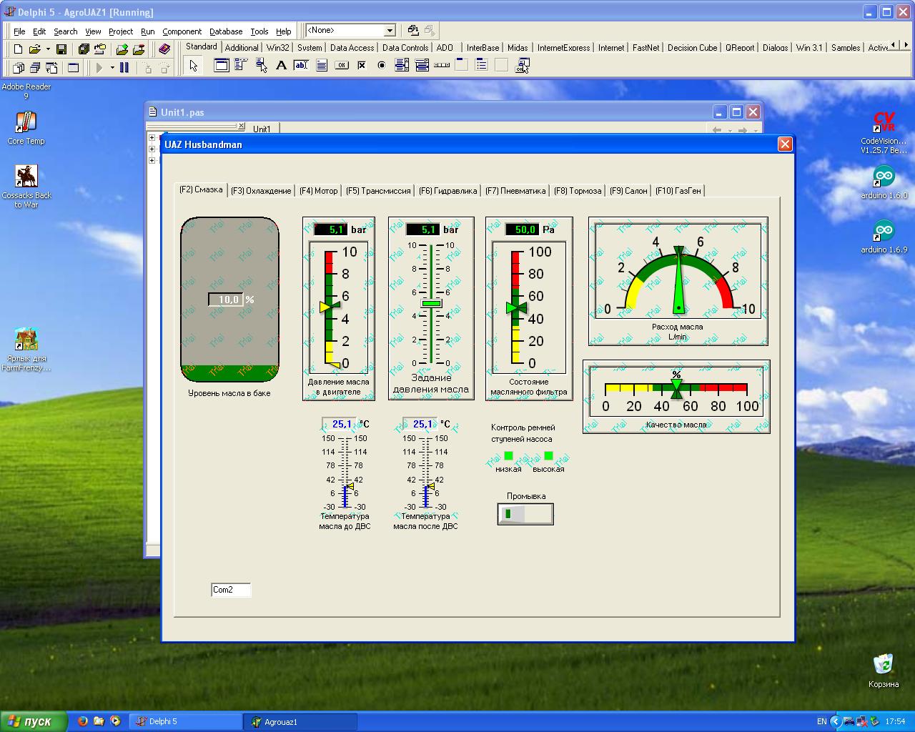
8) the output of various information and the input of valuable instructions for the electronic components of the car on the vital systems of the UAZ is assigned to its on-board personal computer, controlled by a self-made program on Delphi 5. The beautiful components with arrows and buttons are not mine, but thanks to the non-greedy person from Germany (?) who created them and posted them online, including in the form o f a trial version.
The main problem now is writing beautiful and correct code. First of all, we need a normal protocol for the exchange between control units on the Arduino and PC. Because there’s a lot of interference in the car, and we’ll have to transmit quite a few parameters (and that’s just for now, using the lubri c ation system alone):
- oil level in the tank
- the oil tem pera t u re at the engine inlet
- the temperature of the oil at t he outlet of the engine
- oil c onsumption in liters/min
- delta of oil pressure b e fore and after the filter
- oi l pressure after the filter
- revolutions of pulleys of an e lectric motor and two pumps
- measured oil quality (Transparency? Electrical conductivity? The tangent of the loss angle? A resource from an l ast r ep la c e m e nt? A friction machine?)
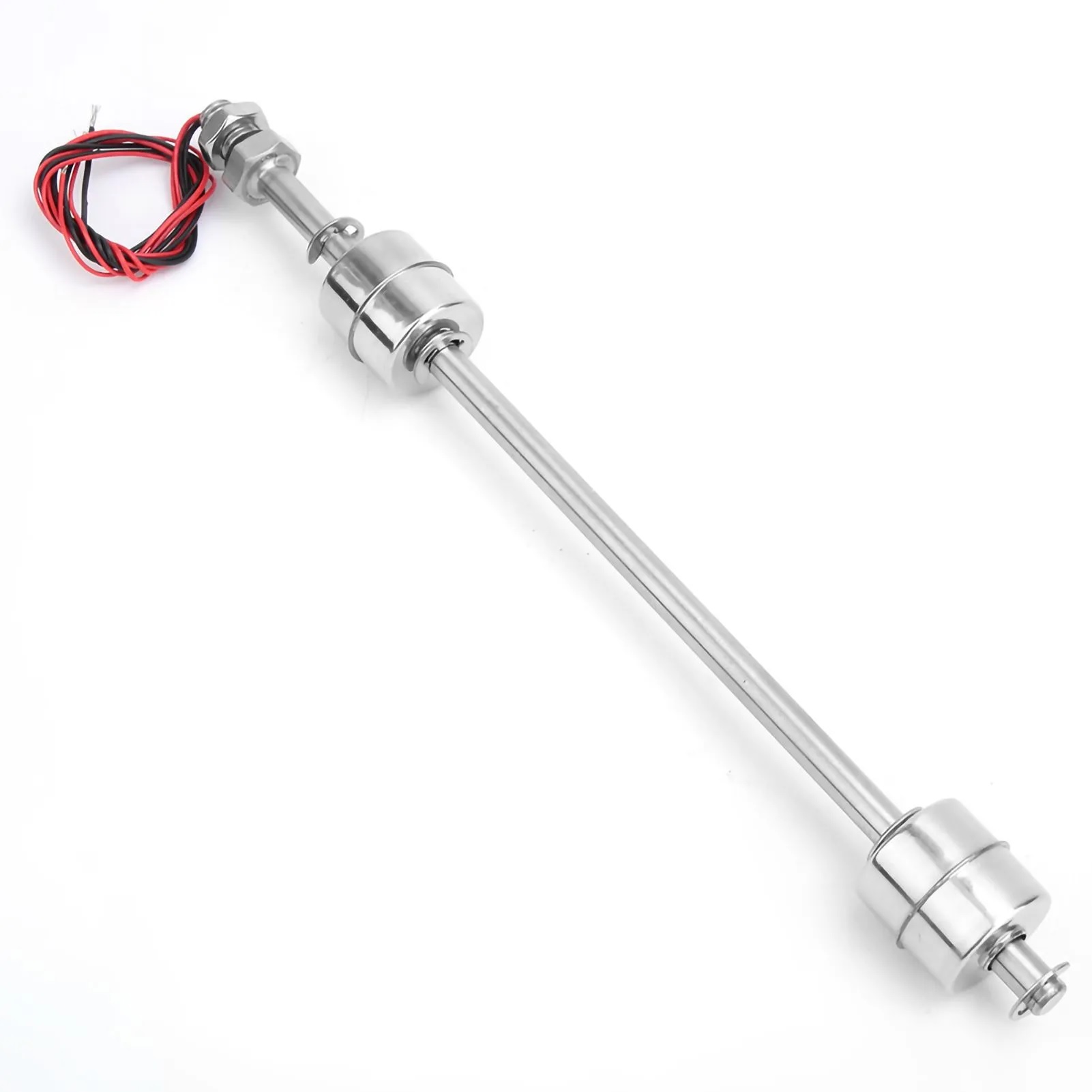
I will try to make an analog oil level sensor in the tank from such a float one, if it turns out to replace the reed switches in it with several Hall sensors so that the magnet moving away from one of them begins to affect the next one. And then the program’s job is to recalculate this into a linear output signal corresponding to the oil level in the tank (it was not good to go into a field with a half-empty or too full oil tank, for example, from antifreeze). The tech world has been turning digital since the days of Samsung washing machines, but the choice of what to entertain a car enthusiast on the screen in the cabin lies entirely with the automaker. This UAZ was lucky: a car enthusiast is an automaker, and the two of them, I hope, will agree on all t h e n e cessary buns in the car. 
The setting of the oil pressure in the engine and the signal for flushing the oil system without starting the engine wil l g o back to Arduino from the PC.
And if there were ready-made libraries for the Modbus protocol for Arduino, then for Delphi 5, unfortunately, the search for a ready–made component to work with the same protocol has not yet led to success… It was also not very successful to quickly sketch out your own exchange protocol - even with a ready-made example for Arduino, to transfer functions to Delphi. I couldn’t do it for the computer… it’s a pity that we didn’t teach languages at school – according to a programmer I know (who can even reprogram a bald devil if you find a command system for this devil), it is linguistic knowledge that is needed to write beautiful and not crooked code, and not in the exact sciences. And Russian is a l a n guage or C++ is not important.
But writing and polishing software can be done on long winter evenings, so in order not to waste precious summer time, this post will be supplemented later with software successes. For the first tests, the already written code is enough, and the signals are somehow transmitted and rec e iv e d through the COM port component.
An announcement for subscribers who have decided that I have already described myself from this project (but where am I going to go from a submarine!). This summer, ac c or d i ng to the plan (perhaps too bold):
- a robot on the gearbox (near the starter, a tube to the clutch cylinder is already visible, which does not go forward to the driver’s feet, but back to the air drive). There was no money for the truck ZIL brake chambers, which Dmitry Azeev strongly recommended, but the desire to quickly switch gears using buttons and smoothly squeeze the clutch with an electronic pedal overcame even such a small thing as temp or ar y and chronic financial difficulties.;
- front and rear attachments for replaceable mounted agricultural equipment, as on tractors, with auto coupling triangles (the cylinder was bought a long time ago, the auto coupling triangle was cooked, and recently the long-awaited SHS-25 articulated bearings came to continue the work on the topic of attachments, and very recently a 42mm metal crown for t he i r installation into an iron structure);
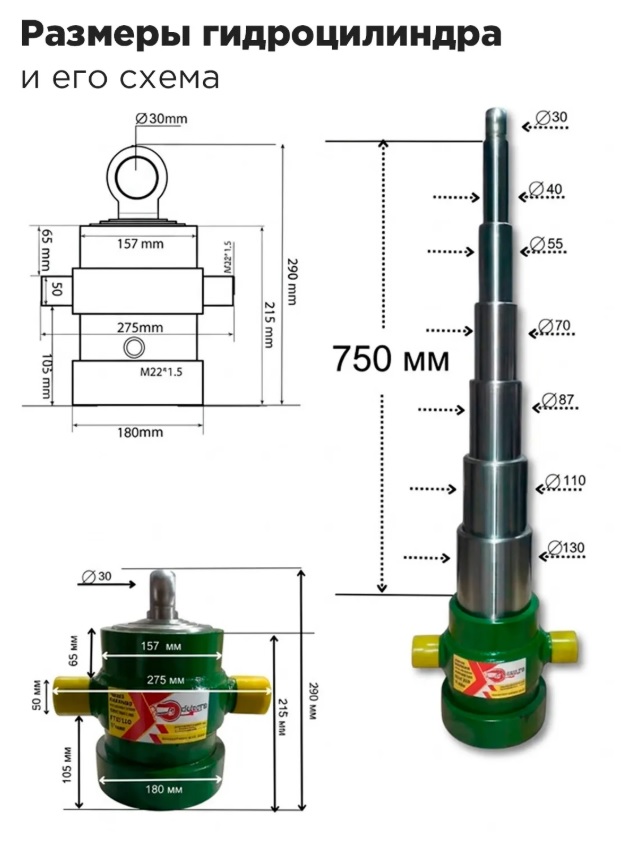
- a replaceable body with a hydraulic lifting cylinder (such a handsome man should arrive very soon at the nearest order pick- u p p o int of one of the Russian marketplaces).
As a result, the children (with such a UAZ!) they should want to become husbandman after all, which means that all the b est things will eventually go to the children!
P.S. I don’t understand where the extra spaces in this message of mine come from - I’ve already corrected it several times, but they still come back. Maybe it’s because of the VPN.