I like screw type chunkers because of lower cyclic loading.

I like screw type chunkers because of lower cyclic loading.
Hi.
A collection of small DIY spiral-shear systems are in this video.
It does CC languages translate pretty well:

S.U.
Screw style chippers generate a lot of friction as the cutting blade is dragged across the wood. Rebak is a shearing action and doesn’t generate that kind of friction though the blades need to be sharp in order to shear rather than crush.
If the chipper is PTO driven, the tractor probably has a surplus of power so a screw chipper works well. But if the chipper is being powered on a stand along basis, Rebak should be easy to drive. And if you use a flywheel on a rebak chipper, it can handle bigger branches as long as you let the flywheel recover its speed.
Thanks a lot for the input. I will have to just go slowly and see. I did do a fair bit of ‘farmers research’ as you called it. And in that regard it seems to be about average for the kind of wood I will be processing. And as I understand mechanics, the hip bone is connected to the back bone is connected to the neck bone is [etc]. Meaning that if I stick something in the chunker that is too thick, the weakest part will break. The belts are for sure weaker than the axle so I imagine the force will ‘escape’ over there rather than twisting up the axle.
I will go slowly and incrementally and see if it holds up. Go slowly with what diameter of wood I feed it too.
Next step is to make up a 1:1 size model using scrap wood. Just to see if it all works out in terms of ergonomics and how the parts fit together.
Hi there everyone! It’s been a little over a month and I thought it was time for an update. I didn’t post about the prototyping and component gathering phase because I was just too busy. But now I have started welding some things together and I actually have something to show.
First a video showing the prototyping. I just threw this frame together in about an hour from absolute garbage wood. But it served its purpose in giving me a 1:1 model that I could stand around and think. Do ‘practice cuts’ and try out the ergonomics. The top PTO is 25mm / 1 inch at 843 RPM. The bottom one is 35mm / 1.37 inch at either 520 or 700 RPM. Their directions are different. The reducer in the video is 12:1. With an RPM of 843 for the top PTO, I will end up with 70 RPM on the working axle.
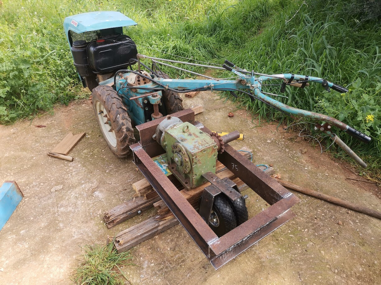
Here’s a shot of the first bits of frame I welded up. Had a local machinist cut the beams because I still find it difficult to cut very straight cuts with the angle grinder, and these need to be spot on if the machine is gonna be square and plumb.
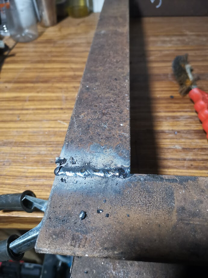
My first weld on this thick of a material. I find that it is much easier to weld thick material then the thin stuff I am used to! Happily surprised by that!
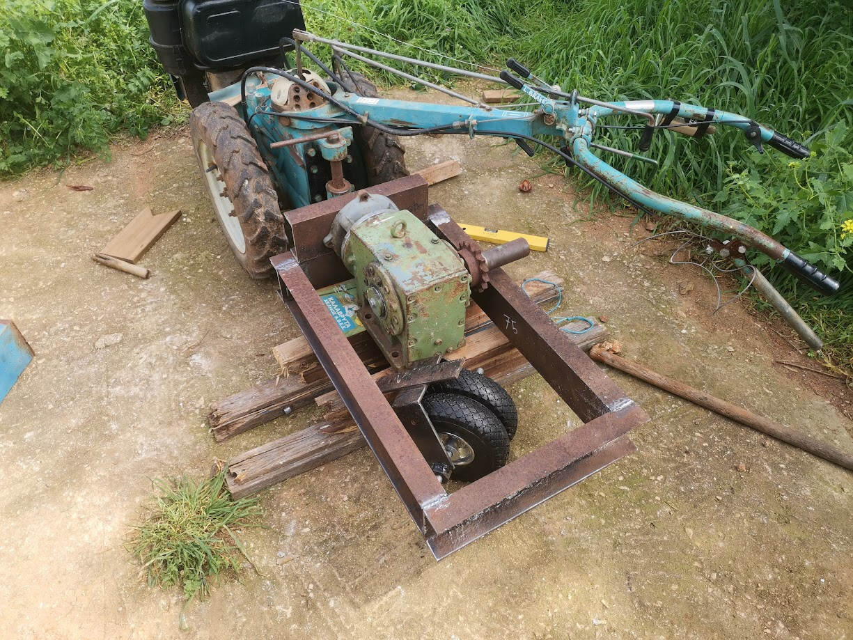
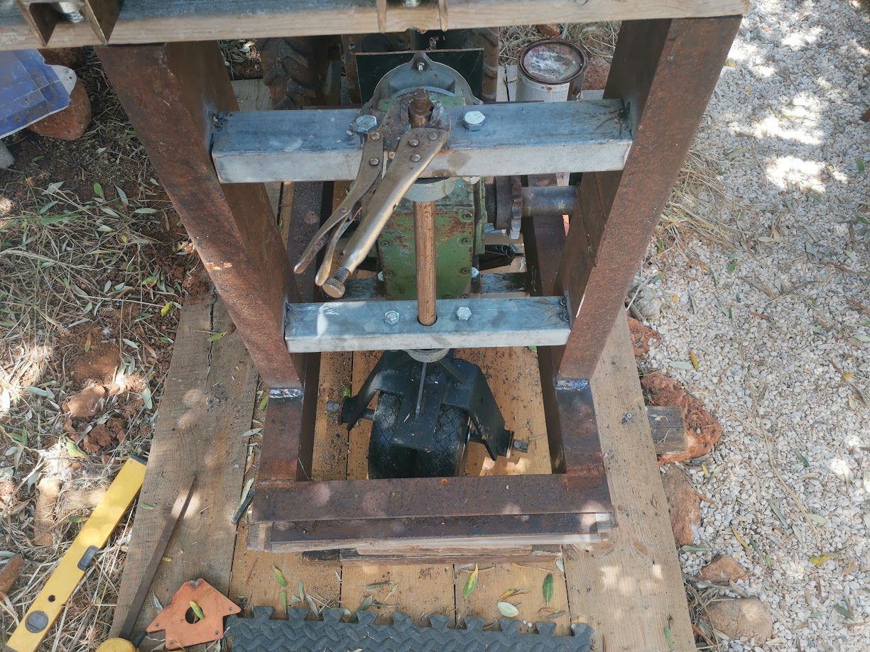
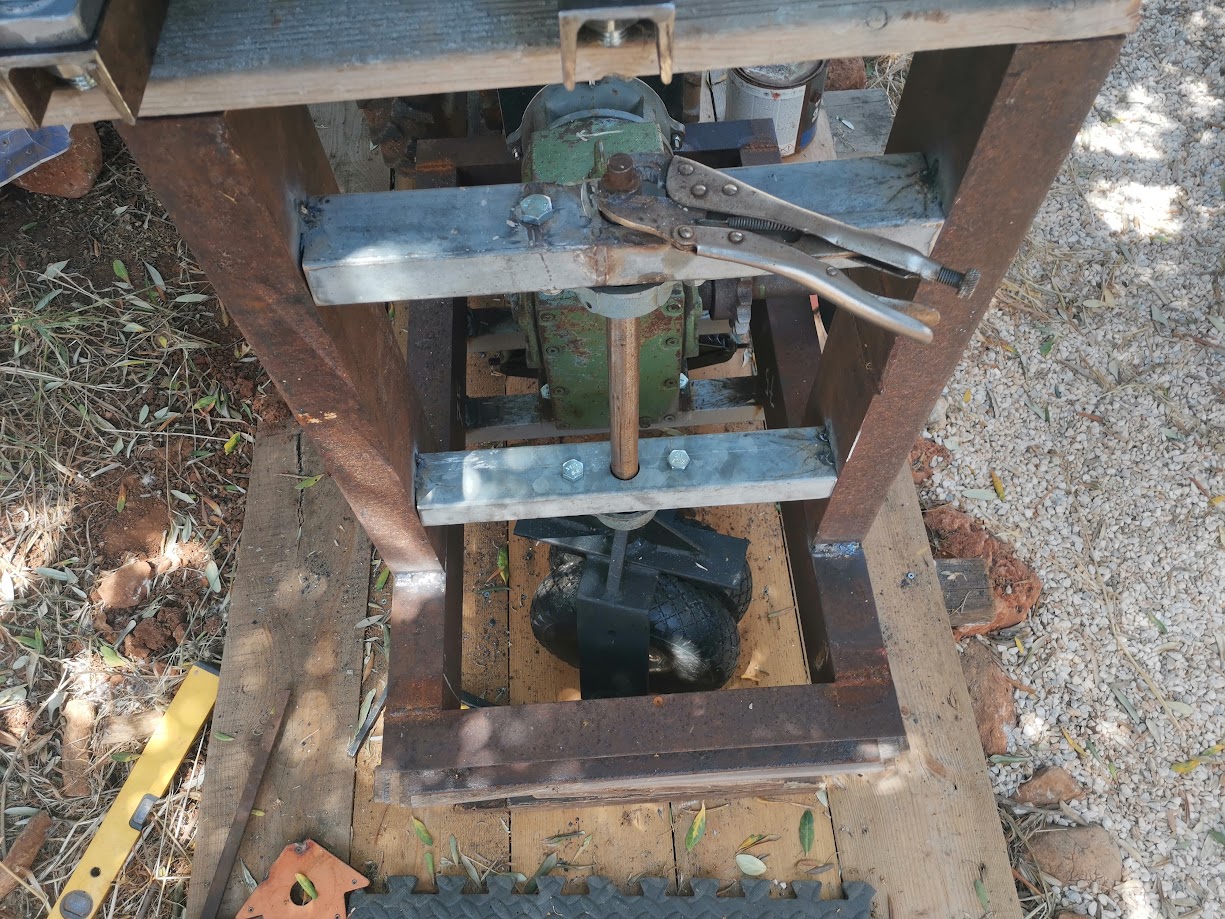
I also welded up a frame to hold the backwheel. And in this picture you can see it turned so that the tractor would turn right.
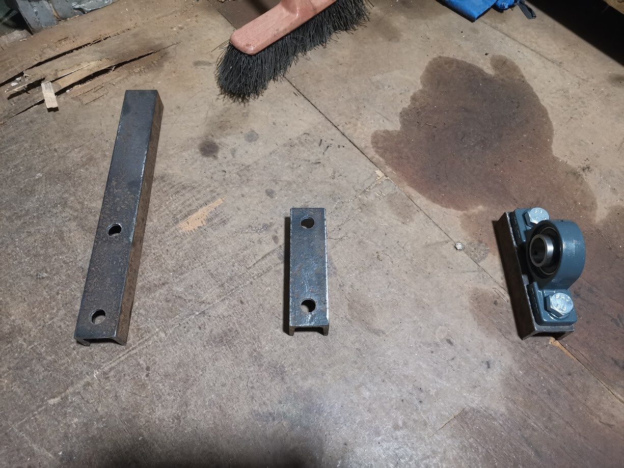
Supports/spacers for the bearings I made up. As you can see in the video, the chipper blades are a bit larger than the bearings; spacers were needed and I also needed a way for the woodchips to pass underneath of them. This will do both. The long one on the left will support a cutting platform for the chunker as seen in this video.
The ‘hubs’ for the axle were some old, imperial nuts I found lying around. Everything is metric here so I was never gonna use them. This should be plenty sturdy I imagine. They are about an inch thick, maybe more.
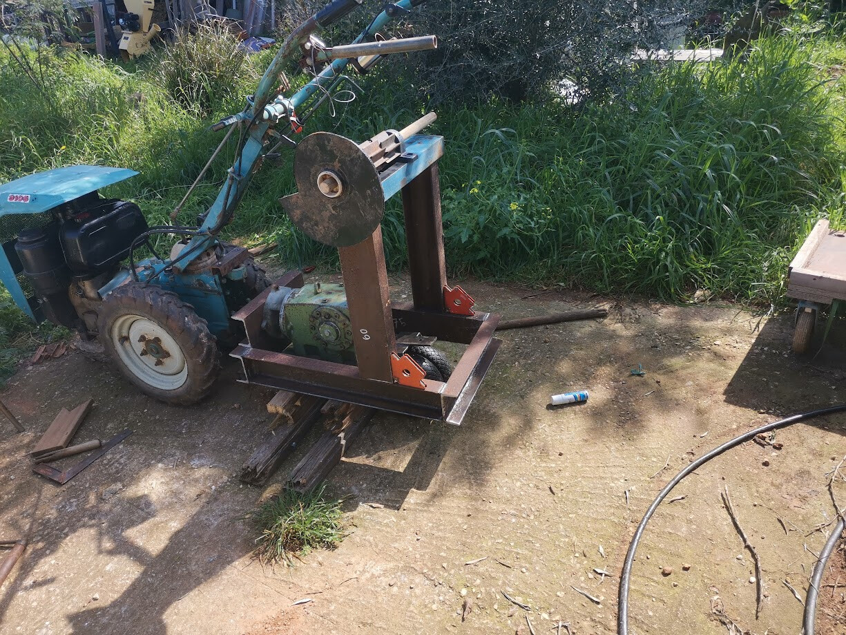
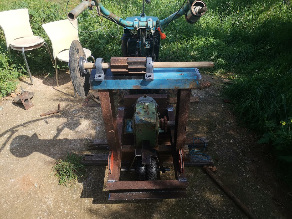
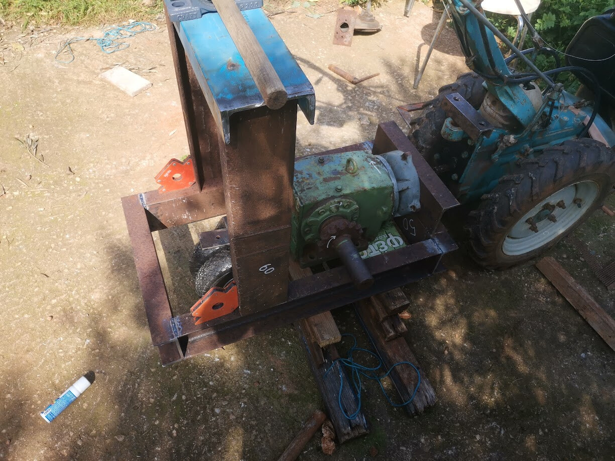
And then finally three pictures of all the parts in place.
I am very happy with the progress, I have plenty of time to think about every step and to come up with the best/sturdiest way to put things together.
Looking forward to your feedback!
Edit: Corrected a few mistakes
Hello,
You’ve already made good progress on your machine, congratulations! 
I don’t have much experience in this area, but I’ll still give my opinion. 
Personally, I would add two small diagonal braces (one on each side) to increase strength when the belt is under tension.
I would also add a forward/backward adjustment at the top (the blade area) to adjust the belt tension.
Cheers for the feedback!
Diagonal braces are definitely in the pipeline. I will probably use that same C-Channel that I used for the spacers. And I have thought about how I could build in some adjustment. For now I have settled on not welding the uprights into place until I get the belts I need.
And I also intend to make a belt tensioner which will act like a clutch. Like every homemade chipper / chunker I have seen online this thing will look and feel like an amputation waiting to happen. So i want to make a footpedal on the side of the machine that has the chunker. It will allow me to step the fuck away from the machine and it will automatically just stop working (or at least, the deathtrappy parts of it).
This clutch would look like a horizontal bar that you press down whilst you work, it connects to an axle that travels through the machine in the same direction as the working axle. It ends up on the other side of the machine, where the belts are; and its held by two bearings on each of the big uprights. The foot pressing down will engage a similar cam-mechanism on the other side, which will hold a drum that presses against the belts.
I was going to suggest braces. It is high so there will be vibrations that are leveraged pulling at the welds at the bottom, then you will also have some twisting because the torque is not centered. I don’t know if it has to be c-channel strong. You could probably get away with typically less expensive angle iron, however, you use what you have and what is your best option. 
As a note, the big miter saws for wood can work to cut straight with a big grinding wheel on them. There issue is the motor and cooling, and little bits of metal dust.
The other option is essentially a motorized hacksaw. David Gingery has one in his books but there are certainly other designs. They are slower then bandsaws or chop saws, but typically less dangerous and the blades tend to be cheaper. However, getting wear across the whole blade is an issue.
I have the c-channel and I’d rather overbuild it… ^ _ ^
I have thought about investing in different tools so I can do all of the work myself. But it’s not like I am doing this kind of thing on a daily basis. Not even a yearly basis. So I decided to pay the 15 bucks that the machinist wanted and do all the parts who don’t need to be exact myself. Especially the upright supports needed to be exact, if they’d be off by a mm or two in opposite ways I would be in a lot of trouble. I guess I could fix it with a thick amount of weld but I don’t want to risk doing things improperly when I will be working with 144hp in torque lol (12 hp x 12 from the reducer).
If I am going to invest in something its probably going to be a proper bench drill and some decent drills to go with it. That I see myself using on a monthly or weekly basis!
Today I worked on a method of coupling the device with the tractor.
The tractor came with a mounting system for a trailer. It’s two thick metal rings welded onto 16mm thick plate and a long pin that passes through both.
I have started work on a mounting system where the two rings pass through a metal plate and still get secured by the locking pin.
But as I was working on it I burned my little 800w grinder. I got slowed down some by that but in the long run I am better off for it because I ended up buying a new grinder. I go by something Adam Savage says: “First buy the cheapest working tool to see if it works for you. And then if it works well and when you can afford it, buy the best tool you can afford.”
So I bought a 1700w Fein! Oh my god I have never seen a machine this powerful yet feeling as controllable! It’s miles above anything I have used before.
Anyways, here’s some pictures of where I ended up so far. Soon I will get to drill those circles I have drawn out.
The part I have been working on. Essentially a faceplate / flange to join up with the existing mounting system. It’s a piece of large C-channel that I added a plate to so it ends up thicker. I will end up welding all of this together soon.
And here it is joined up with the existing pin system.
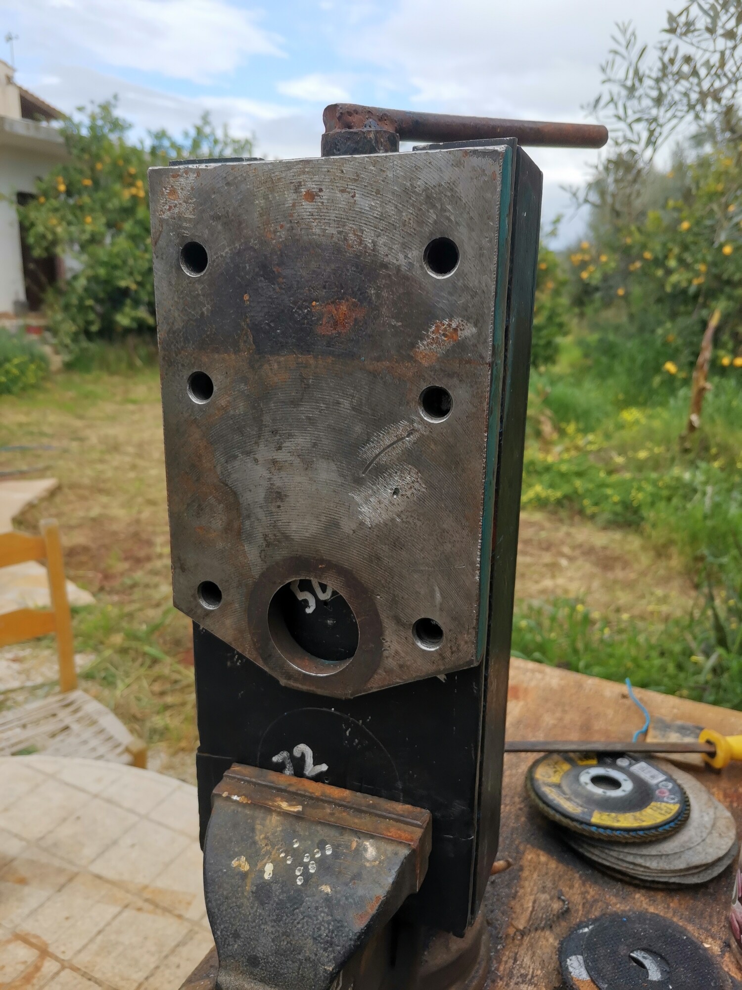
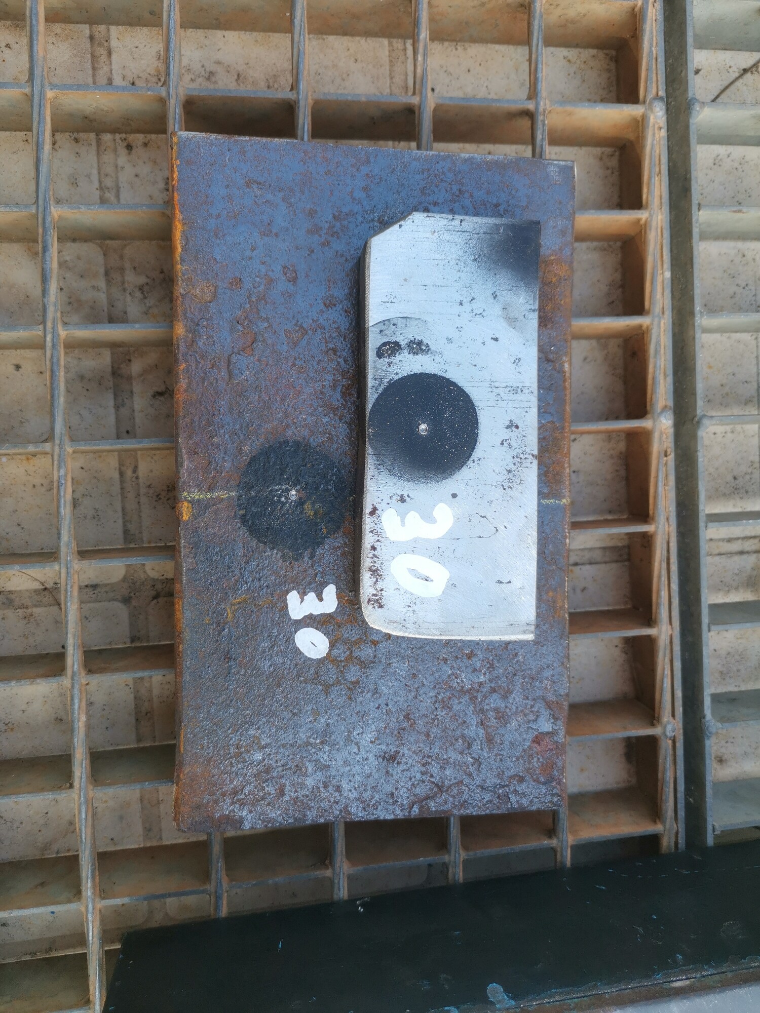
I will still add two horizontal plates with holes of 30mm that will give it all a lot more rigidity. The metal I have for that is 16mm, but I don’t think I can drill that thickness of metal and I don’t own a hole saw of that size either. So I will ask a local machinist for that.
That is it for now. Not so much progress but it’s something. And I ended up buying a really great new toy 
About 20 days have passed since the last update. I am almost at the most expensive part of the process; getting the crucial parts machined to my specs. But first the drilling and welding of the faceplate.
I ordered some holesaws and drilled 48mm / 2 inch holes into the mounting bracket/faceplate; these two holes give space for the two PTO’s to go. Here it is in its near final position; this will eventually sit a bit lower. I will cut into the top bar of that horizontal C-channel and lower it almost to the bottom bar.
And here’s that weld  I don’t know what I was so scared of, this shit is easy!
Hahaha, I spoke too soon. Welding inside the C-channel was freaking annoying. These are the pieces of 16mm / 0.6 inch of plate that receive the pin. Having to work around stuff and having to drag right to left, really messed with how I was able to control the puddle. Lots of pits, bubbles and slag that barely wanted to come off. I was running the amps up high so at least I am sure I got good penetration (even if they are ugly as hell). Also the way this is set up the forces are being transferred into the C-channel, none of the welds should be under any load. Tell me if I got that wrong!
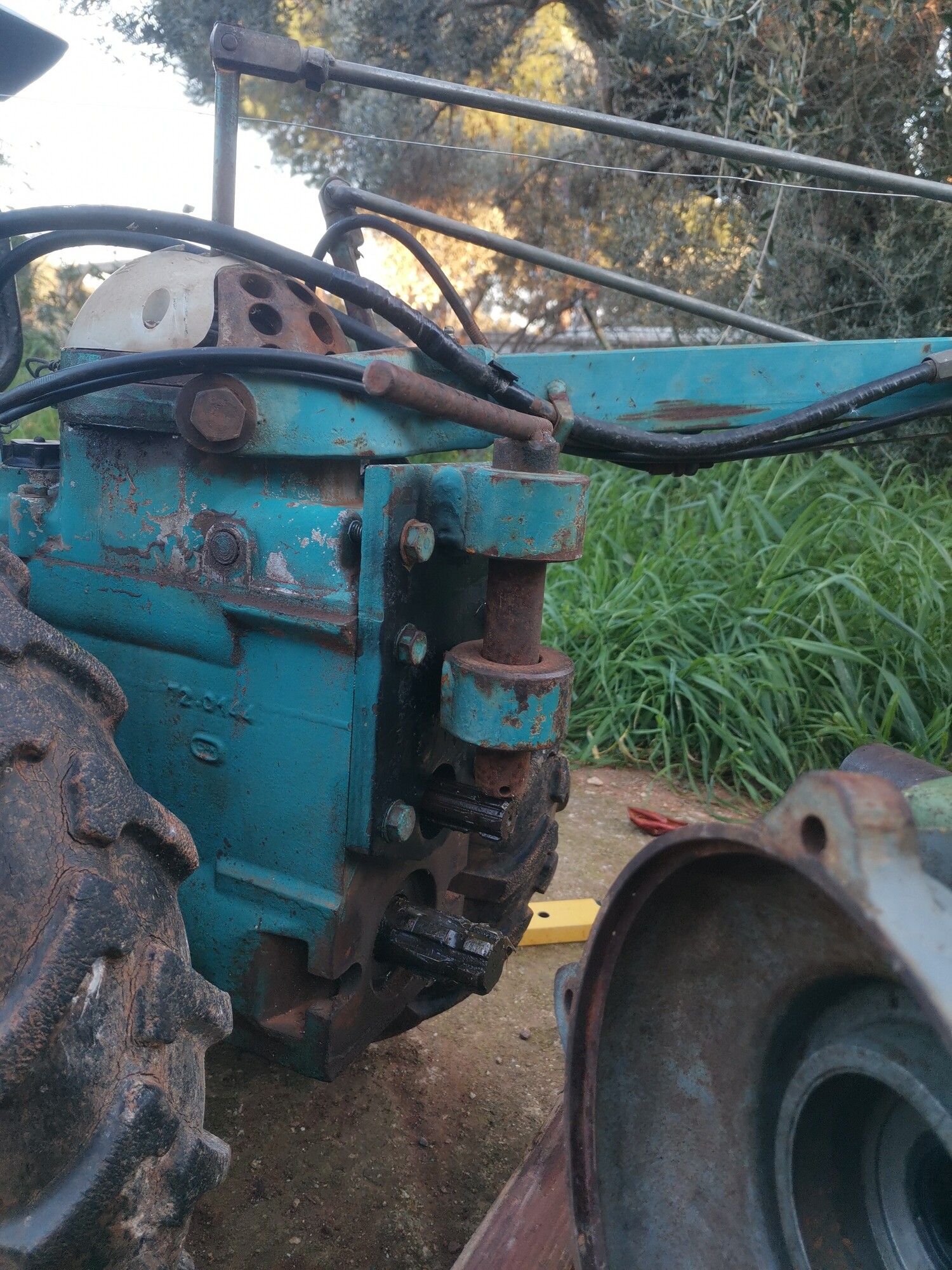
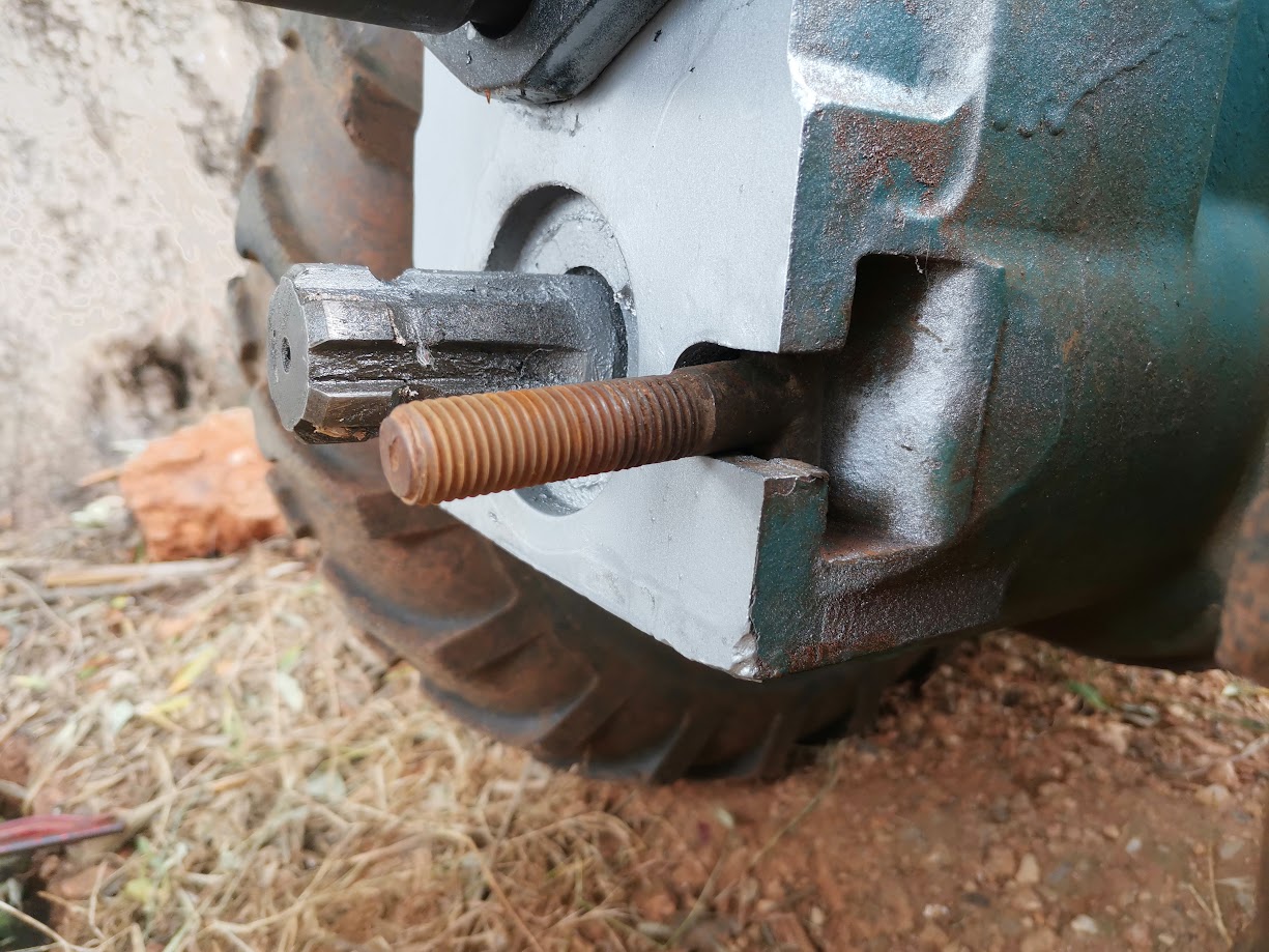
This is the wormgear that drives the reducer. I can’t fit it onto the original shaft right now because it took quite some heat to even get it off. Keep this position in mind, I will remake this part. Next picture shows the final position and part that will be remade.
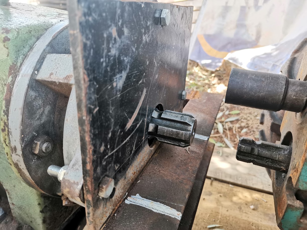
Here the original shaft is placed in its original location, with the new part that will be modified to replace it in the foreground. So that nubbin that sticks out of the middle of the plate there, will be the end of this new PTO shaft. The nubbin is better visible in the next picture.
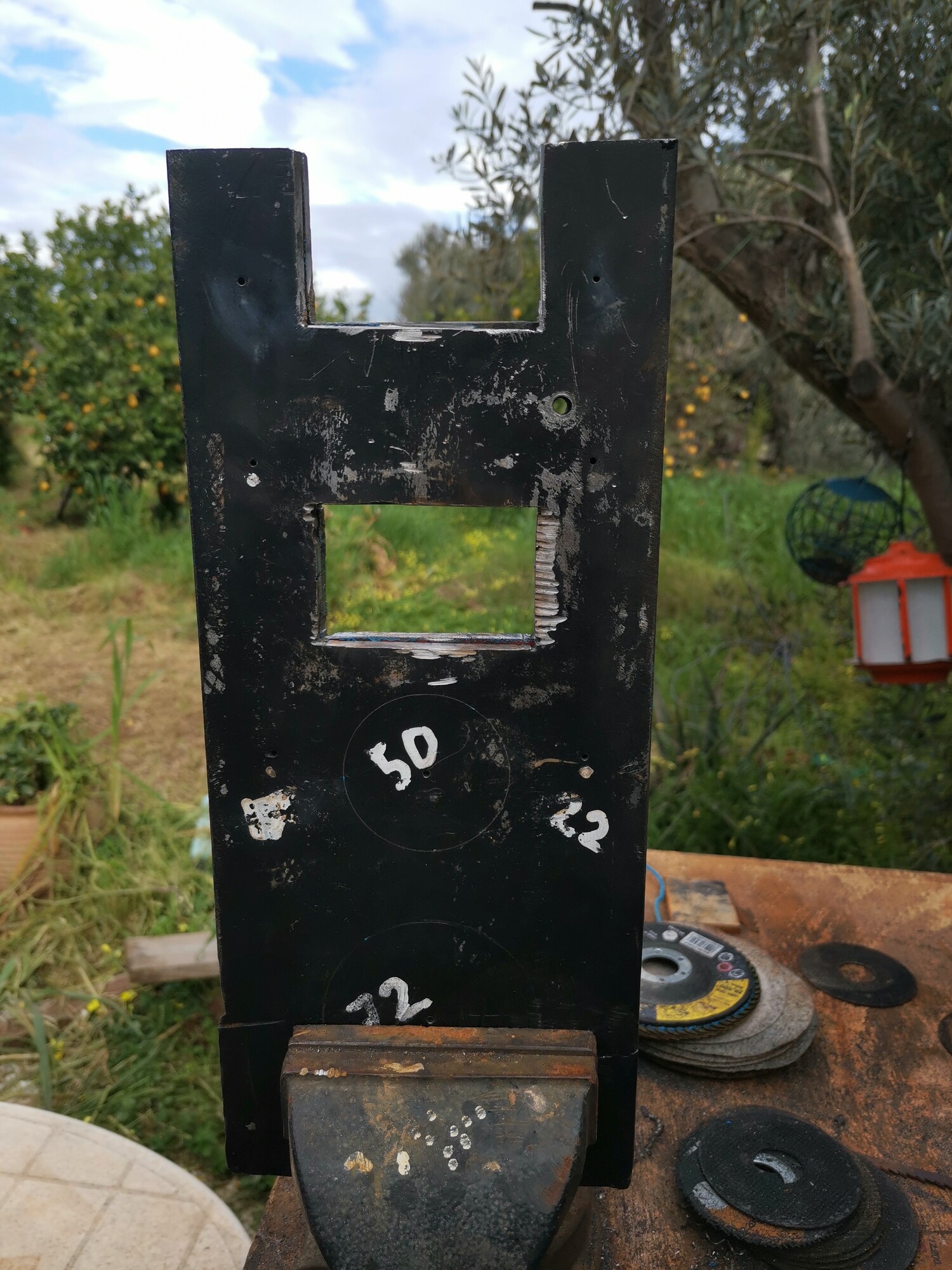
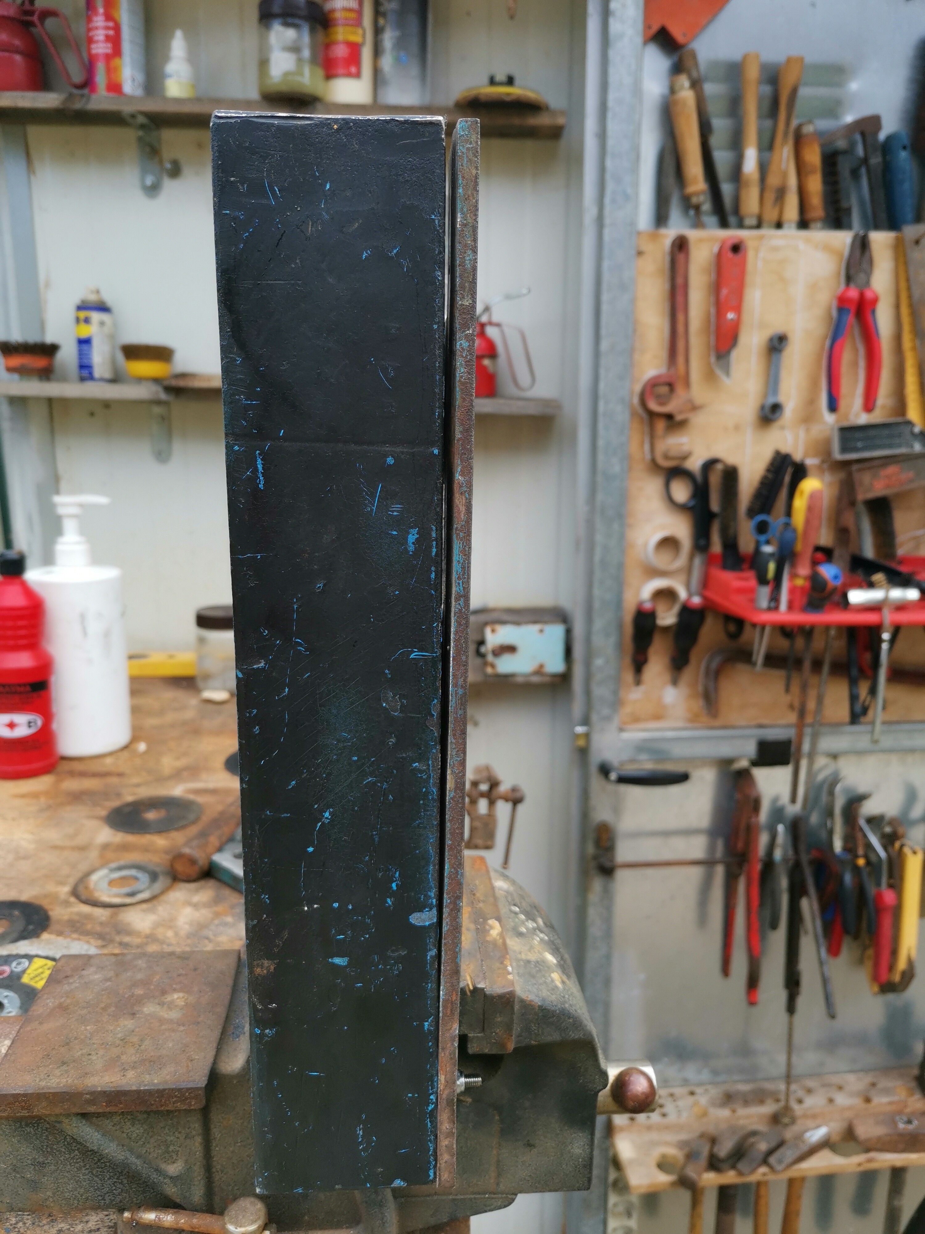
Now this pictures needs some explaining. The straw represents where I need to cut the C-channel so the faceplate can be slotted in. I hope this will give it plenty of strength, the faceplate will also be welded to the black plate with the bolts through.
Secondly you can see the ‘PTO’ is nicely lined up to the coupling that sits on the small PTO of the tractor. Two male PTO’s will join through this coupler (25 → 35mm).
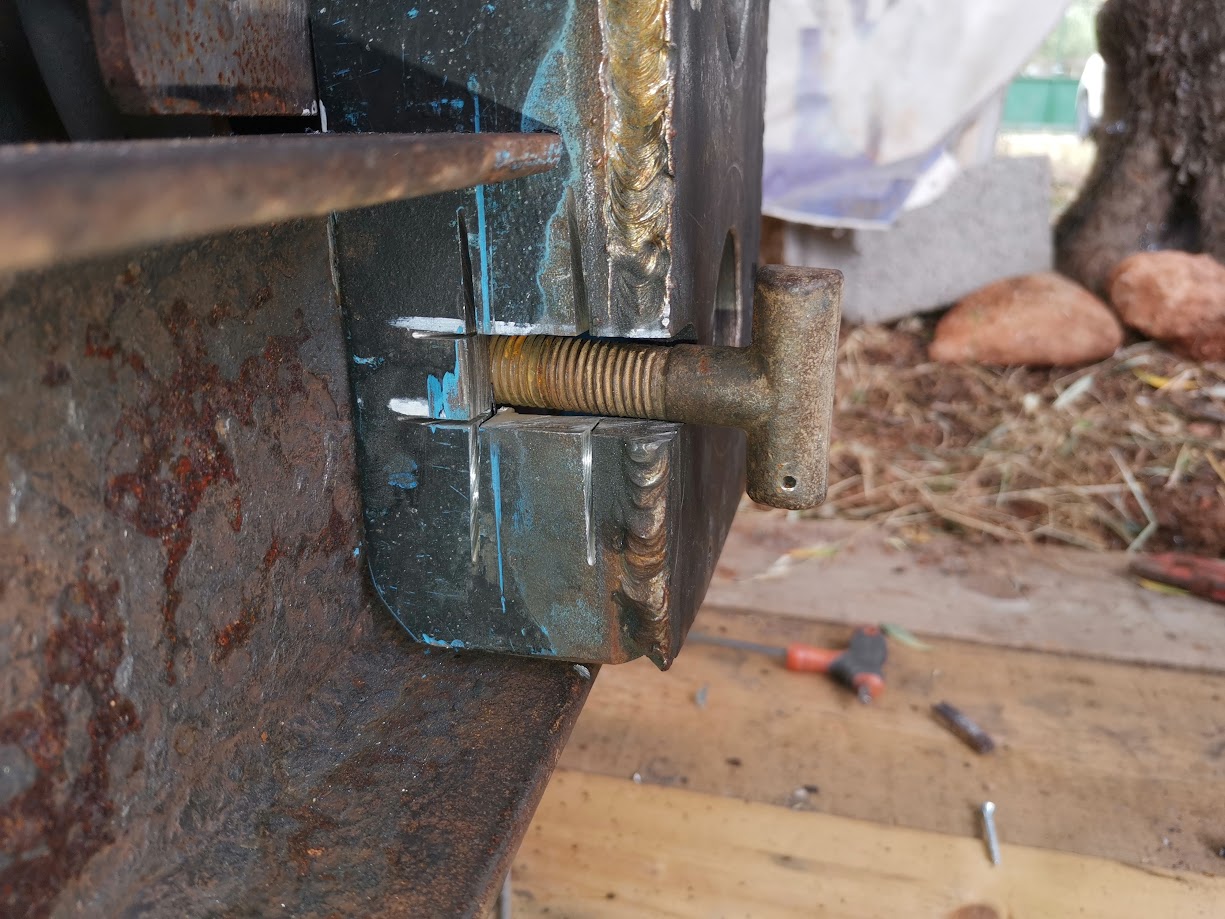
Lastly, in the bottom right you can see two horizontal paintmarker lines. This is where the rotortiller connects to the bottom PTO using two T ended bolts. I am trying to still allow for this method of attachment, whilst also keeping as much of the metal as possible. They are really thick bolts (16mm+)
Here you can see how much of a bodger I am lol. I took the measurements for the faceplate, cut it weeks ago and only just now realized that somehow I got it wrong. The faceplate was supposed to be at least 25mm / 1 inch lower so that it could interface with the C-channel on the left and I could weld it up all nice and solid. It’s way short and I’m going to have to figure that out somehow.
Anyhoo, it’s going along nicely! Again, not too fast but also not so slow that I am getting frustrated. I saw a video on youtube that said that it’s more difficult to switch from working with wood to metal than the other way around. This is because metalworking takes so much more time. I can definitely agree with that!
Next update I hope to have all the parts that I need to start putting things together!
Alright, it took me a bit longer to get to the next phase.
BUT! Today I finally got to pick up the pieces for the Kastoras 
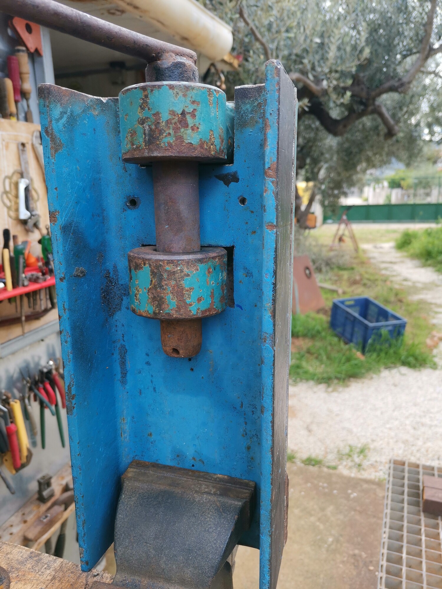
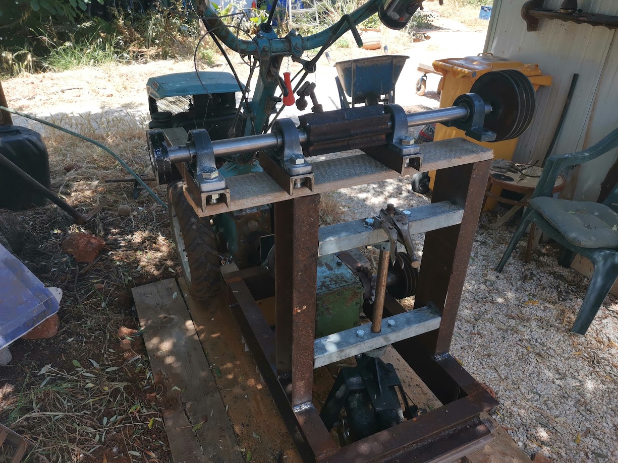
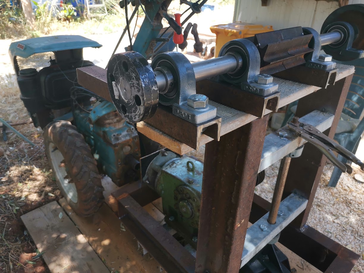
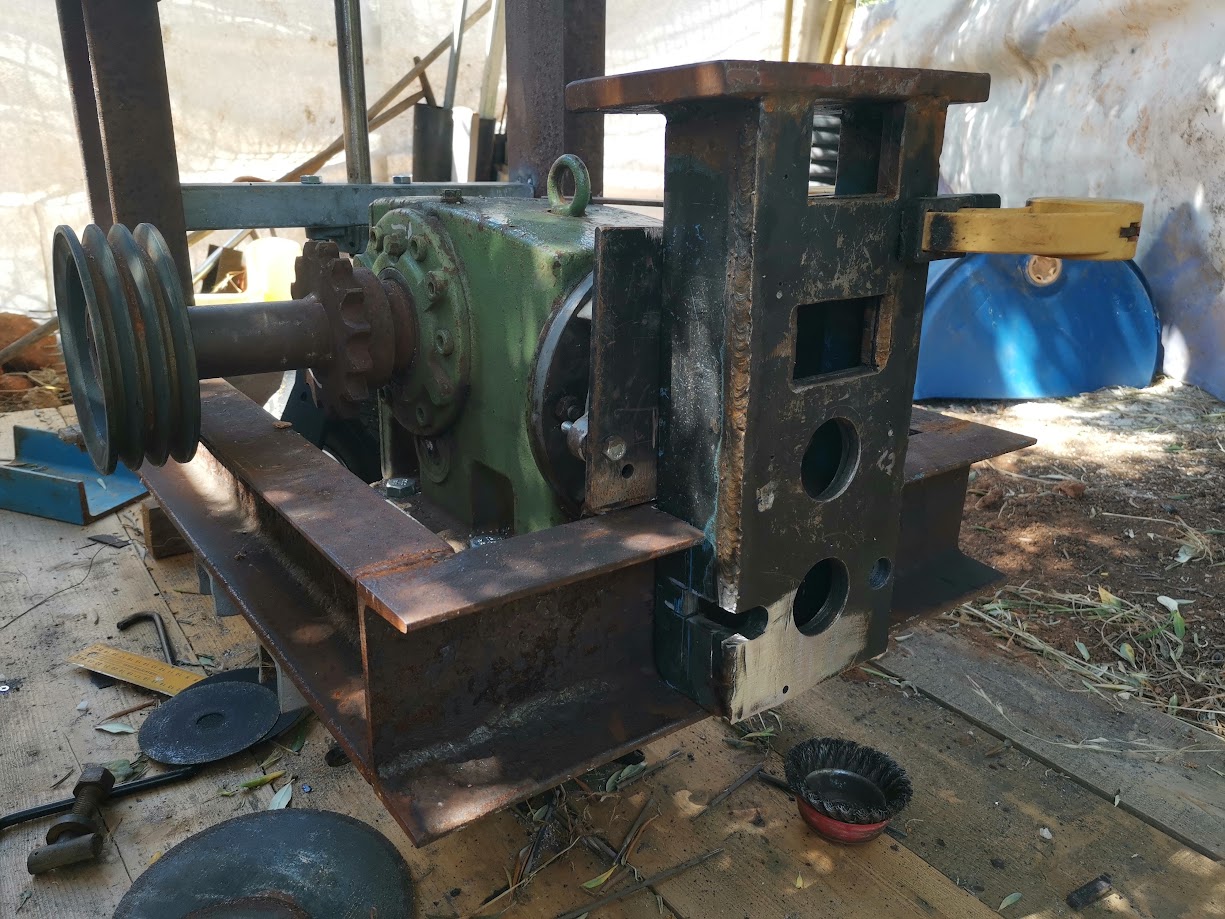
Here you can see all the parts in their future position, I was too excited to fit everything together to make a picture of all the parts separate. That might come later. First the main axle. Note that piece of wood representing the channel iron and the axle are both sticking out further towards the left. Past the frame essentially. This is a change from the original design and will allow me to stand at a more ergonomic angle when everything is done. The cost in the axle was only slightly higher and it affords me a better standing position when I work.
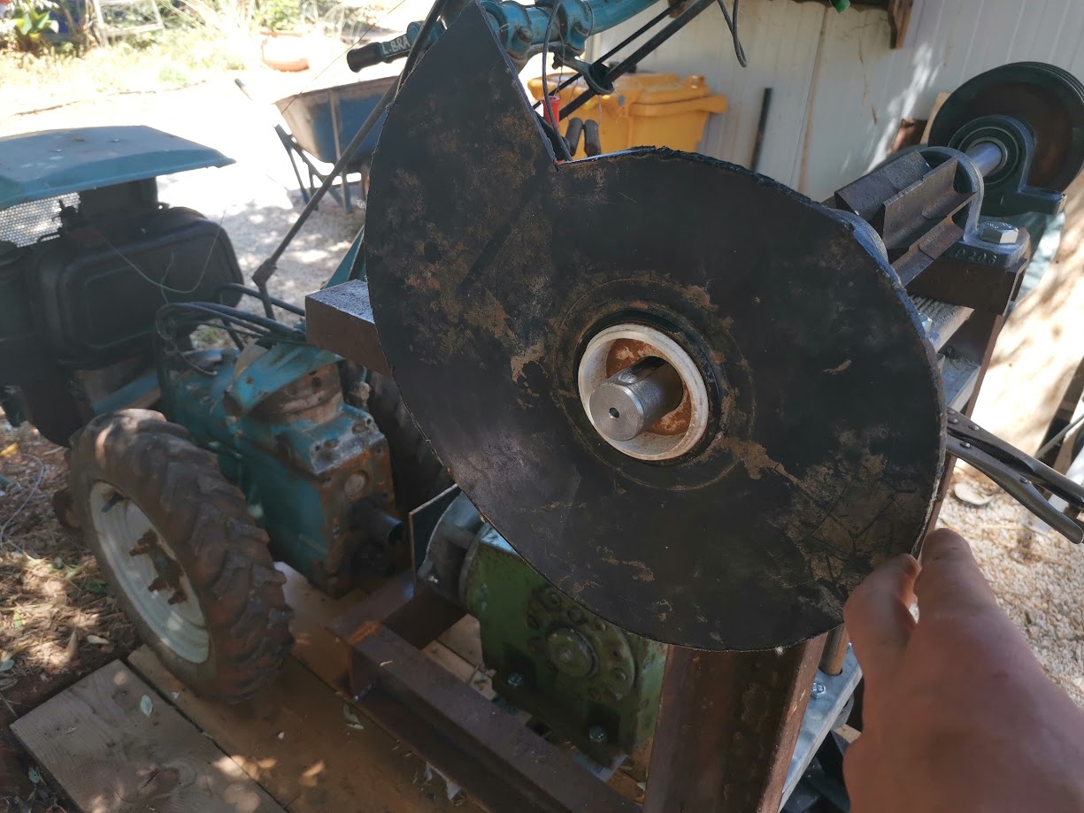
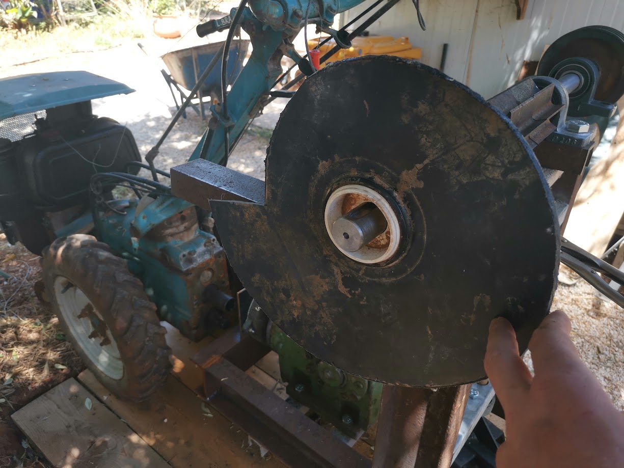
These two flanges will hold onto the future chunker knife. I am still thinking about the means to connect these onto the axle. It has a keyway, still need to make a keyway into the flanges. I could weld one on, but that is quite permanent. Maybe I need to ask the machinist to make me a flange with a collar from scratch? Found a 40cm circular sawblade for sale online that will be acting as the chunker. My brother is sending me that by post (Hey hoi! ) It has teeth that could be sharpened, so I believe it is a nice high carbon steel.
Here it is with the ‘blade’ in two positions, showing you how the blade will be cutting. Now imagine a small table affixed to this piece of smaller channel iron; like a tablesaw it will surround the blade.
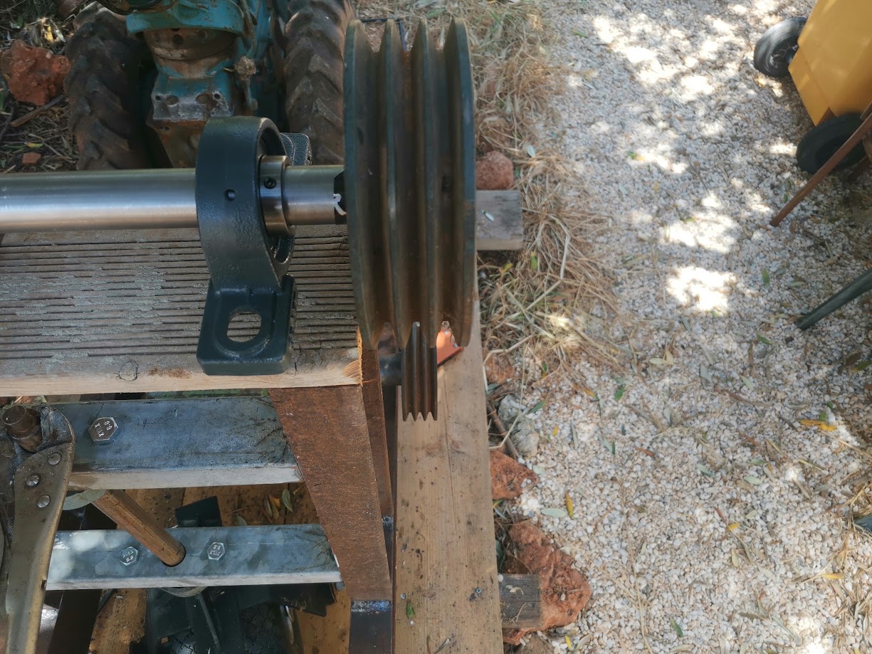
The pulleys are lining up nicely. I will tighten the belts using a kind of camshaft / roller / clutch mechanism. I will be able to press a large foot lever, which will pull down a locking pin, that will in turn release the tension that keeps the clutch in place. In short: I will have an emergency stop.
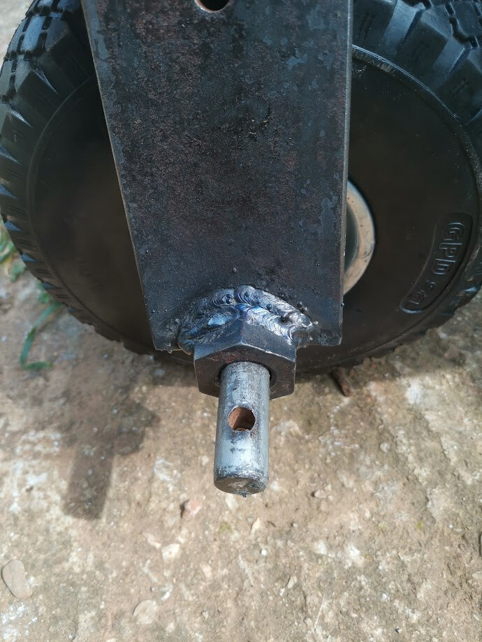
Here’s the wheel mechanism tack welded into place. I believe that I put in enough wiggle room that I can still move the whole frame up and down for alignment. The face plate is the determining factor in where the wheel will sit. The shaft that goes to the wheel will be tightened down using captive nuts in the bearings, then I will weld a washer underneath it to secure the position.

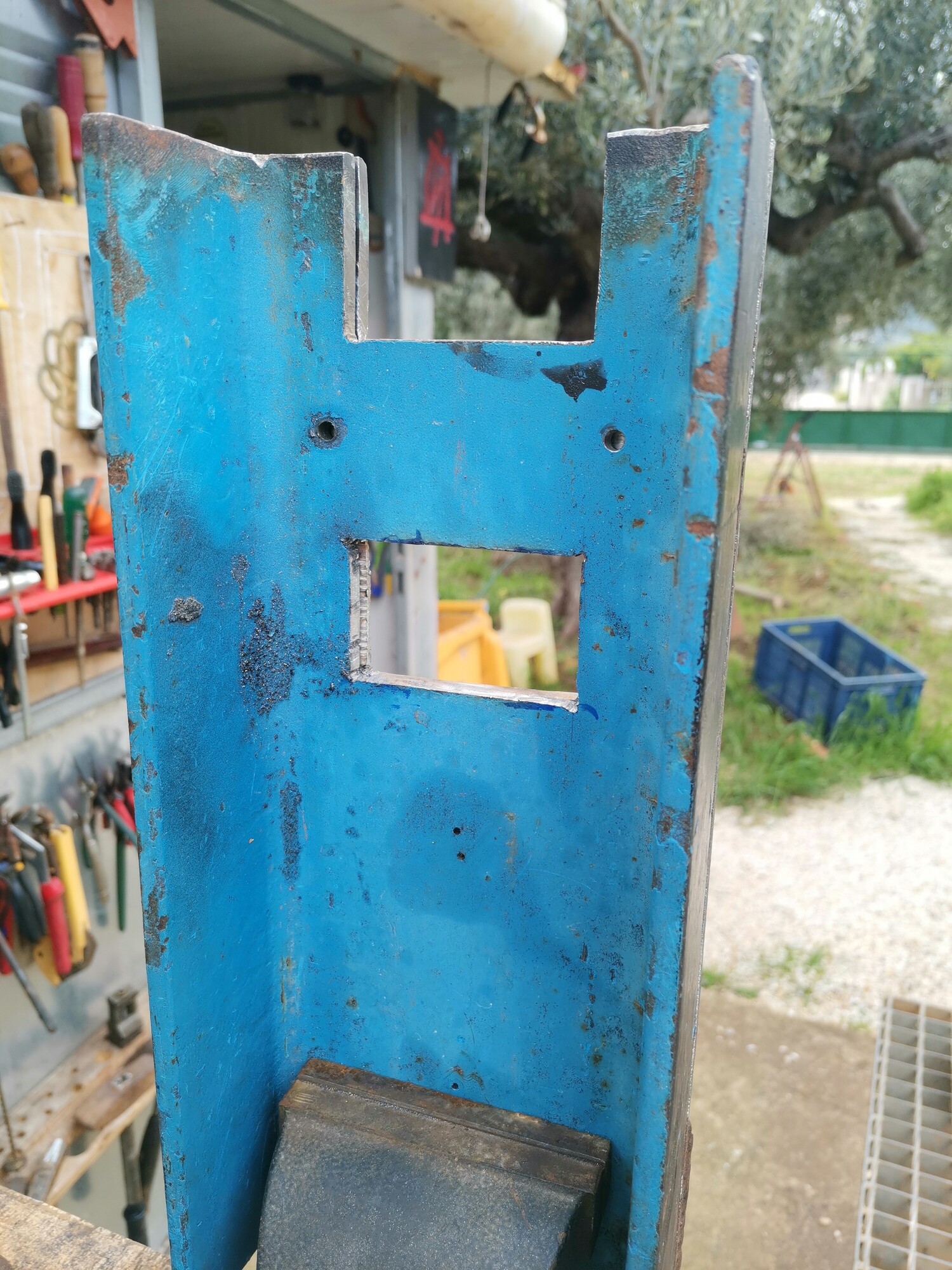
I cut the top channel iron to receive the faceplate, here you can see it held into place temporarily.
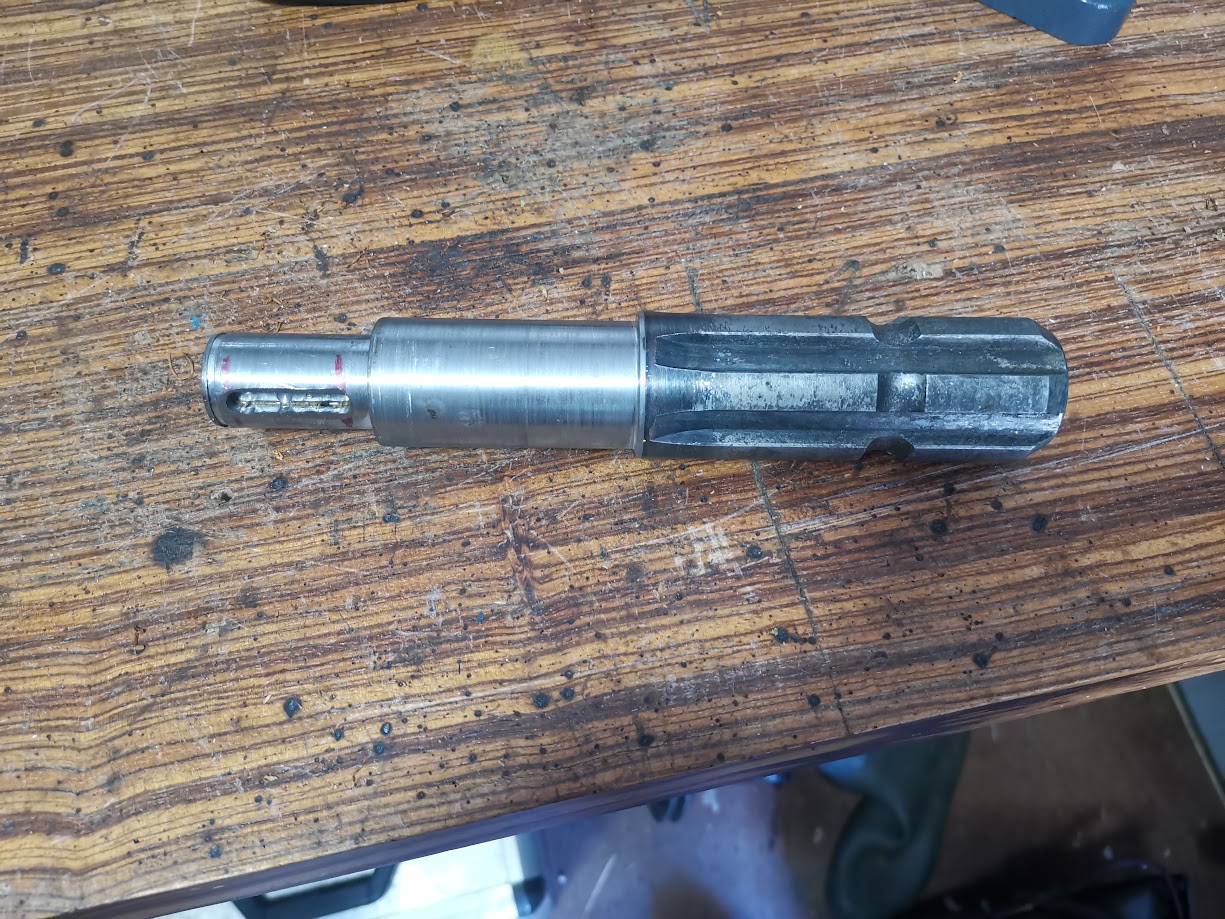
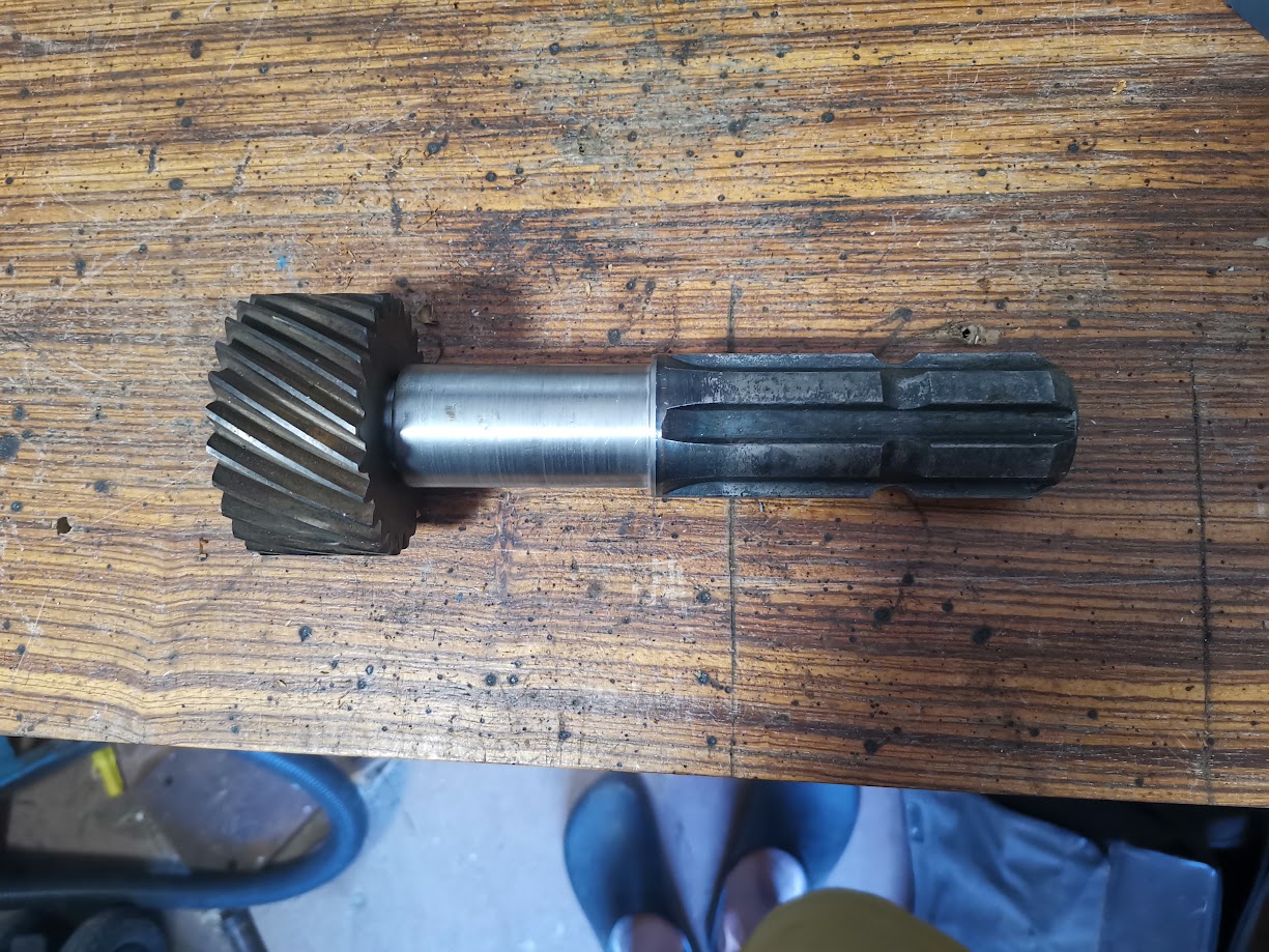
Below you can see what I have come to think of as ‘the nubbin’. The gear engages with the wormgear inside the reducer and I have made a new shaft for it. The shaft comes out slightly and ends in a PTO, which will connect the Kastoras with the Bertolini. The Bertolini came with a rotortiller that had a coupler already, in the 3rd picture you can see the coupler sitting on the top PTO on the right. I am overjoyed that I was able to get these measurements correct! Because I already sunk a lot of time into the faceplate.
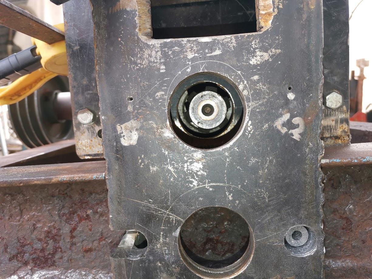
Here you can see the mounting system for implements like the rotortiller. I still have to figure out how it will connect to my faceplate… Currently I am thinking to drill two holes above and below the slot I have already cut out, connecting them into a kind of ‘Plus sign +’, allowing me to fit in a nut and spanner. I want to retain as much material of the channel iron as possible. In the last picture you can see how I made the holes in the faceplate.
And that’s it!
I would really appreciate hearing some feedback! Especially concerning the two flanges I want to use for mounting the chunker. Should I go back to the drawing board and make a flange with collar from a single piece of steel?
Hooray! Yesterday I managed to run my very first test! I connected the reducer to the tractor and it ran fine.
First my little ramble about the test setup.
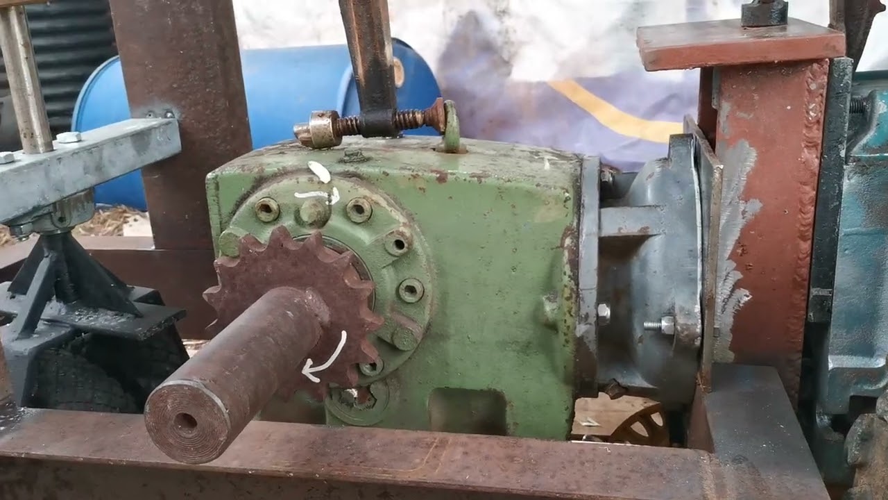
And here you can see it working! The massive clamp did fall off just after this video ended, so I didn’t really get to test it for the RPM or anything.
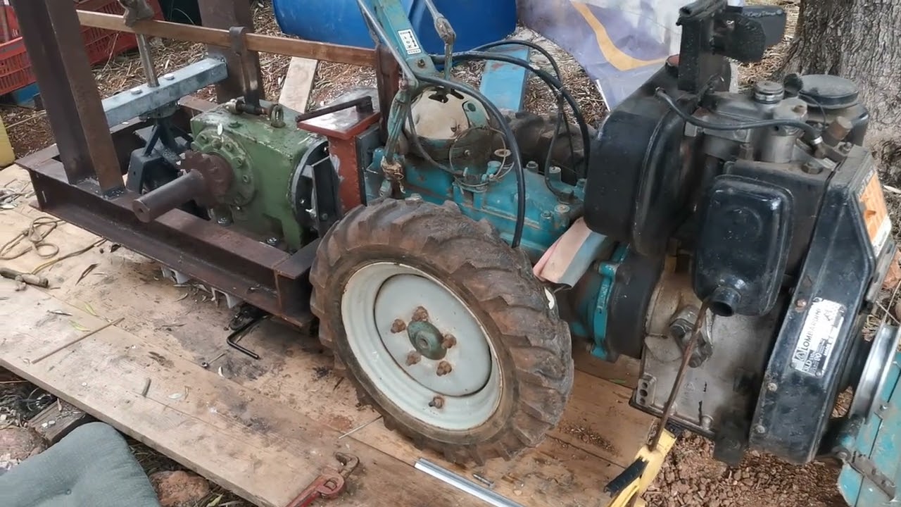
This morning I woke up around 6, put in a few tack welds and inspected all the parts to see if they were still aligned or had been rubbing. They did not rub so I started welding everything together.
More updates soon!