Hi Kyle , All the units I have bought are the cheap nasty power jacks , but the latest 2015 LF onwards ones , no messing straight as they come outta the box .
As mentioned if you have an hour or so to read , its just that it gets interesting how these guys go about turning a cheap nasty Chinese inverter into one that can match and in some cases exceed the performance of the more expensive units on the market , BUT after a year or so it seems that the makers of the units ( power jack ) have taken notice of these guys woes with them being power thirsty and have addressed that and a few other issues making a out of the box no messing half decent unit for a fraction of the price .
But like I said if money is no issue then go for what ever you think will do your job .
Dave
You really only need the temp pole inspected. RV pole, that is. An electrician I worked with did the same thing.
In some places the electrical inspectors have the authority to charge you based on nothing more than observing wiring from the street they suspect was not done under a permit or up too code.
Charges can be heavy fines and even jail time.
I have done a little more research on this grounding issue, and understand it better now.
Here is what I have learned so far. Please correct me if I am wrong.
There are really two categories of grounding.
The first category is “equipment grounding.” In this category, equipment chasis, faceplates, breaker boxes, solar panel racks, exposed metal parts, etc. are connected to earth ground.
This is to prevent the metal parts from becoming electrically charged if a loose wire comes into contact with them, etc That would be dangerous because, if you touched the charged metal, you might provide a better return path for the current (esp. if simeltaneously touching a water faucet, etc.) leading to an electrical shock. It also provides a ground path for lightning strikes, etc.
Almost all systems should have this type of grounding.
The second category is “electrical grounding.” In electrical grounding, one side or the other of an electric circuit can be connected to earth ground as well. For example, if the negative terminal of a battery was connected to earth ground, then it would be a “negative ground system,” and if the positive side was connected to earth ground, it would be a “positive ground system.” With AC current, there is really no difference between the two legs of a circuit. So, calling one “neutral” and one “hot” is merely a matter of convention. And, by this convention, “neutral” is generally connected to earth ground. However, whichever “leg” or “terminal” is connected to earth ground, the other voltage (potential difference between the two legs) is now “referenced” to ground.
For whatever reason, it became customary in the US (and some other places) to tie one leg of power to earth ground (what we call the “neutral” leg).
However, it is possible to have neither leg tied to earth. There are many obvious examples. Your cell phone is not tied to earth ground. Your car is not tied to earth ground, etc.
This is called a “floating ground.”
The National Electrical code permits floating ground in certain alternative energy systems for home power, and floating ground systems are considered as safe (or arguably safer) than earth ground systems. However, there are some additional requirements since neither leg is tied to earth. For example, both power legs must be fused or have a breaker and a disconnect.
As discussed above, my specific area of concern is using an automotive style inverter (which is presumably designed for a floating ground) in a home power system.
After more research, I understand the problem somewhat better. A large inverter designed for home use (such as a Magna-SIne), has an isolation transformer in the output stage. In other words, one coil of the transformer is connected to the DC side of the system, and the other coil in the transformer is connected to the AC side of the system. Therefore, there is no hard-wired current path between the DC side and the AC side, and no harm is done is both the DC side and the AC side are referenced to earth ground (or not).
However, with smaller solid state inverters, there is no isolation transformer. The current merely flows through the electronics from the DC to the AC side of the system. Therefore, if the AC side neutral wire is referenced to ground, and the DC side is referenced to ground, then the path through the neutral leg of the inverter can become the “preferred” ground path for currents, thereby frying the delicate electronics.
As Dave said above, the simplest way to cure that potential problem is to dereference the neutral leg from ground on the AC side. Then, there is no possibility of the preferred ground path being through the inverter’s electronics (at least under normal conditions).
However, I do wonder if simply dereferencing the DC side of the system from earth ground would not accomplish the same purpose and, if so, that this might be a better solution? After all, you could still maintain chasis grounding on the DC side, and the voltages are lower on the DC side of the system.
Frankly, I don’t see a great deal of advantage to not making the entire system a floating ground system (with appropriate chasis grounding) but I may be missing something.
PS: As I have stated before, this is an “experimental system” and I am not concerned with code compliance from a legal perspective. However, I am concerned with safety, and I realize that the Code can be a good guide to safe practices (although there is always more than one way to skin a cat).
Wording is a problem here.
I have a lot of the same issues discussing this subject with guys in the UK.
( boy do they have some strange wiring and rules ).
You ground once.
Once only…
The place you ground is literally the ground rod, and it’s connection to the common bar in your panel board.
Everything else is a bond.
Bonds tie all the non current carrying metal components together.
The bond is the bare wire in any cable that you attach to the back of a box and the " U ground " screw of a receptacle
( I hate calling that a ground it screws people up ).
From here on I will call all wires not connected to the grounding systems ( rod to the common bus ) Bonds.
You can have a safe a ungrounded system.
If everything is balanced and in good order the system will naturally find a floating point where the common white wire is capacitively coupled to ground and floats within a few volts of this point most of the time.
The danger comes from the fact there is no solid connection to ground and if there is a short circuit TOO ground nothing will trip or give warning unless you have a specific ground fault detection systems running ( this has been a code requirement for a very long time ).
An ungrounded system will continue to operate with one leg grounded and give no warning ( unless GFCI protection is there ) until you notice this by getting shocks from this or happen too test with a multi meter and discover one leg is now zero volts to ground, common is now 120 volts above ground and the other leg is 240 volts above ground.
There is also the possibility that even without a ground fault the system is just not well balanced and you have maybe 40 volts on one leg to ground and 200 on the other.
How large is the system?
What are the loads and what else can go wrong?
Well if I were building and designing my own system I would add some power factor corrections and do my best to run near unity.
Reactive power is still load on a system and you still pay for it.
This combination of power factor correction, in some cases a large radial distribution system of its own capacitively coupled to ground can become unstable.
You can get some very odd voltage in some cases its even possible to get 300 volts between a live line and ground ( more voltage than you generate is possible because of the odd things that reactive and resonant tank circuits can create ).
So if that previous part has you confused don’t worry too much about it.
It’s physics and the main point I am trying to make is a good single point ground makes CBs and fuses trip and blow in a predictable way, and that’s something you loose when you run without a solid single point ground.
And voltage stability is assured with a good solid ground because you are pinned to the earth and can’t be moved higher or lower.
In this picture you see a meter connected to a transformer core and it is reading some voltage with reference to a water pipe ( that is bonded )
The core is not bonded and the AC line side is capacitively coupled to the core and the core is capacitively coupled to ground.
You are going to read some voltage here that could be as high as the line voltage on the primary.
The touch potential is very near 120 volts ( depending on the source and could be much more if something inductive shorts to the inside of the core and an oscillation begins )

The way I get around this is Bond the core to bleed off as much of this capacitively coupled charge as I can.
With some luck the secondary will float with its neutral point at or near ground.
This is how I can take a 4160 primary delta and run a secondary delta at 600 volts and not expose anyone or anything to a high potential step voltage.
Furthermore if the system is well balanced and floating nicely each phase will read very near 350 to ground ( without a connections ) while it is in fact a 600 volt 3 wire three phase system with no real neutral point.
How you detect and ground and how you wire protection systems for these obsolete systems ( no one actually builds new systems like this its too unstable ) is a much more involved problem I don’t think anyone here wants or needs to hear me blather on about.
Hi Kyle, what a great bit or info to put up. It brings it all together in a nice package. Thinking about your setup you might want to install a generator subpanel. They are nice because both legs and the neutral wire are disconnected when you flip the breaker. It also has a lockout device so only one source can be connected at one time. I was thinking one side your genny, the other the inverter. It would also make a good off grid main panel if your existing one is old…
f0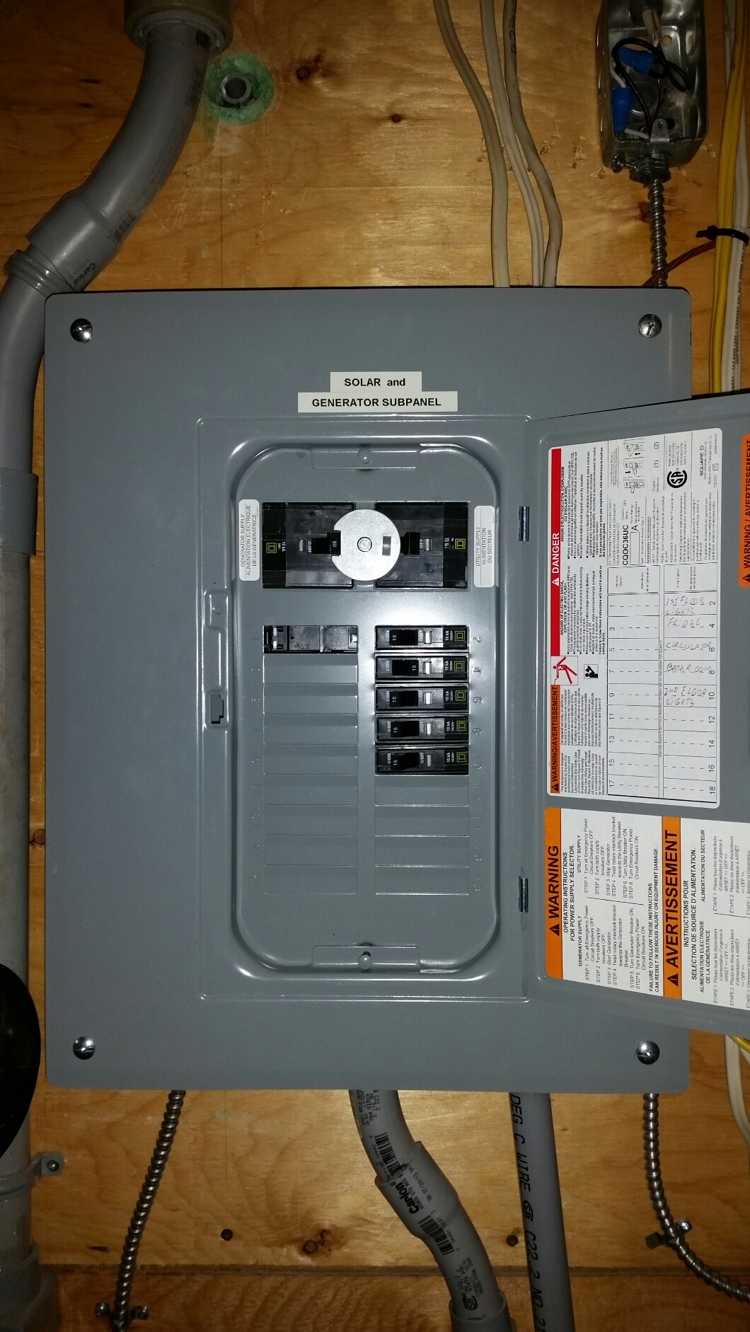
The picture you see is mine. When we grid connected I maintained the critical stuff on solar. This was the best way to do it legally…
Option 2.
The switch ( this thing is as old as the hills my god!!! Still a great switch though and I have a few of these I use for my switching needs with multiple power sources )
Option 3
I REALLY like this kit but never used one.
I think I may jump on it one of these days when I do my next upgrade ( and get rid of some of the antiques I use )
http://www.ebay.com/itm/RELIANCE-CONTROLS-30216A-30AMP-7500W-GENERATOR-TRANSFER-SWITCH-NEW-/190782780203?hash=item2c6b8a332b:g:iQQAAMXQTZhR3Yp0
Option 4
This is a simple kit you could brew up yourself using a Mechanical interlock pair of 3 phase motor reversing motor starter contactors.
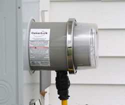
Option 5
This seems to be how the wind is blowing
These interrupter sockets that plug in ahead of your main disconnect.
Utility has to do this for you however and I have never seen of touched one.
I am simply aware of these ( I do not touch homes except my own and I do not even admit to do any.
work in my own home less the secret electricity police catch on )
I rely on a lock out system.
Things I do not talk about…
OK.
I’m excited.
I just ordered a “8000 watt / 32000 watt peak LF Split phase pure sine power inverter” from Power Jack from Ebay for about $350 (incl. shipping).
I don’t normally play the lottery, but i feel like I just bought a lottery ticket.
Anyway, if this thing even works at 25% of its rated capacity, it will be an incredible bargain.
I will let you guys know what happens.
Question,
They say after 20 years(I think) a solar panel will be at 80%. Is time the factor of a panel’s life or is it the amount of sun?
Bill - It is my impression that the 20 year estimate is based on 20 years of actual use; exposure to the elements, etc.
I am under the impression that you could put a crate of solar panels in a shed for 20 years, and they would be just as good when you took them out as when you put them in.
I ask because everyone’s availability to full sun can vary so much. So if they average it, AZ may be under 20 twenty years and the PNW will be over.
That’s a bargain price for a 8000 watt , with currency converting I think you paid a little less than my Aussie $300 one that I bought over a year ago .
I filled in the warranty card that comes with it for online too , just in case I got into trouble with it , or the ebay seller but so far has not missed a beat powering up everything I have
What voltage are you going to be running on your battery bank to the inverter ?
Dave
24 volts.
Which model did you get?
Is it the low frequency version?
yes all 3 of the power jack inverters I have bought have been 24 volt LF , it seems that each year they do some sort of update to these units ( I guess they have been watching the, Youtube video’s of problems } and decided to do something about the workmanship issue’s that came with most of there junk in the earlier years .
If you managed to read more of the storys of what those guys did to units then you will know that was very early into the LF series of this inverter and things have improved a lot since then , but its still worth while giving the unit a little shake ( be carful as its a very heavy unit ) when you get it to make sure there is nothing rattling around inside .
Also have a check of the idle current draw and make sure it is low enough for your use , they have improved that problem , but its best to double check just in case they forgot to put enough ferrite rings on it .
Let us all know how you get on when it arrives
Dave
I pretty familiar with the PowerJacks. That seems like a good deal. I started with a Sun unit which was classic Chinese in design. I loved watching the LED’s blink when it was making power : ) Hypnotic lol I would like to make a few suggestions. First, increase the fan size and monitor the temp. Second, because these are not UL listed, monitor them closely with security cameras. Check your home insurance to make sure this does not put you in jeopardy for coverage. Third, the weak aspect these units are the capacitors and the MOSFEET architecture. They don’t handle surges well. Their MOSFET are inherently less forgiving than IGBT’s. Which brings me to my last point. As in Chinese plasma cutters
(I own two of them) you may be able to do a direct swap of IGBTs without having to do major mods. I would also swap the caps with ones that handle higher voltages. It is really no that much work. In the mean time, you have so much extra capacity, that you might now run into any issues.
I’d really like to do a Powerjack Frankenjack with the above mods! But, alas
I need to get my gasifier done 
I’m pretty sure that when my first one arrived ,over a year ago they had put an extra fan inside of the unit , meaning now there are 2 fans inside and also the Mosfets are German made not sure about the caps though .
Dave
Just an update.
The nasty PowerJack arrived today.
I unboxed it with an unusual feeling of excitement and trepidation.
The unit was double-boxed. That was nice.
I was momentarily distracted by the Chinese bikini babes plastered all over the front (and back!) of the manual. Those guys sure know how to market to Americans.
I flipped the manual. A lot of it was in pidgin English, but I got the gist of it. No surprises, and not a whole lot of information.
The unit itself was shiny and clean. Nothing like the banged up “used looking” units some say they have received.
And it was HEAVY.
I would guess around 40 to 50 lbs.
That’s a good sign.
I took a couple of truck batteries, hooked them in series with jumper cables, then hooked them to the input terminals on the power jack. Some pretty nasty arcing when you first connect the batteries. Surprising since the unit is turned off.
It has two sets of terminals on the back, and I vaguely remember that some website said they both needed to be connected (no mention of this in the manual), so I used another set of jumper cables to tie them together.
Then, the moment of truth. Power switch on. Fans whirl, leds blink, etc. and the green light stays on.
Then I turn on the table lamp plugged into the convenience outlet. Voila, there was light!
So far so good.
I check the voltage across both legs of the 120/240. Everything looks good (except that 1 leg is about 9 volts less than the other leg ???)
I check the idle current draw. Not bad. Around 1 amp @ 24v.
I try the power saver mode. Idle current drops to about 1/3 amp, and the thing detects when I turn the light on (it flashes on briefly, then after a slight delay, it glows steadily).
I decide to try out the battery charger function while it is hooked up to these junky batteries (instead of my good batteries). I use the 120V pigtail provided for the test. No joy. I couldn’t get the battery to charge no matter what I did.
However, I vaguely recall that I read somewhere (not in the manual) that the 240V version will not charge with 120. So, I will have to hook a 240V source up to test that theory.
There is also a small mysterious silver toggle switch on the front of the unit that is not mentioned in the manual. I think I saw it mentioned on some web site, but I don’t recall what it is supposed to do. More research required.
Haven’t done any serious load testing yet.
CONCLUSION
Assuming this thing will carry a sustained load of 2000 watts or better, I would say it is a heck of a deal even if the battery charger never works.
It is not at all clear to me that it it includes intelligent 3 stage charging (the manual says nothing about it), so I am not sure I would trust my expensive batteries to it in any event.
Will report back after I gain a little actual use experience with it.
Kyle, may be the toggle switch is for the battery charger on/off mode? It will be interesting what you find out. The price is sure right. Keep us posted so we can have a kyle’s manual of this unit, here on DOW. Blaze the trail for the rest of us. Thank You. Keep on Gasifiing and solar powering.
Bob
Turns out that the toggle switch makes the fan run all the time, instead of by thermostat.
Also, I found the website that says that this particular model will not charge from 120V, despite the fact that the outlet and pigtail is supplied for this purpose.
Hi Kyle ,
Seems they continue to update these units as mine does not have that toggle switch for the fans .
The arcing you mention means that your unit had been powered up , maybe they now test them before shipping , it just means that the caps are charged up , if I am going to connect to freshly charged batteries I would short out the terminals before connecting so no spark is close to the batteries when you put jumper leads on .
We only get the 240 volt model over here ,and I do use it with my inverter generator running on charcoal to charge up low batteries and so far its worked ok , again I am not so sure it does the 120 amps as advertised , but then again my batteries are never that bad they would take that amount in , if you get a chance maybe you could up load a few pics it would be nice to see the upgrades they have made since I bought my last one .
The UPS side of this unit seems to work pretty good too as well.
Dave