Max, I’m afraid I don’t understand the cranking gas part. I see the stop screw limits the stroke, but what is the chamber and how does it work?
1 Like
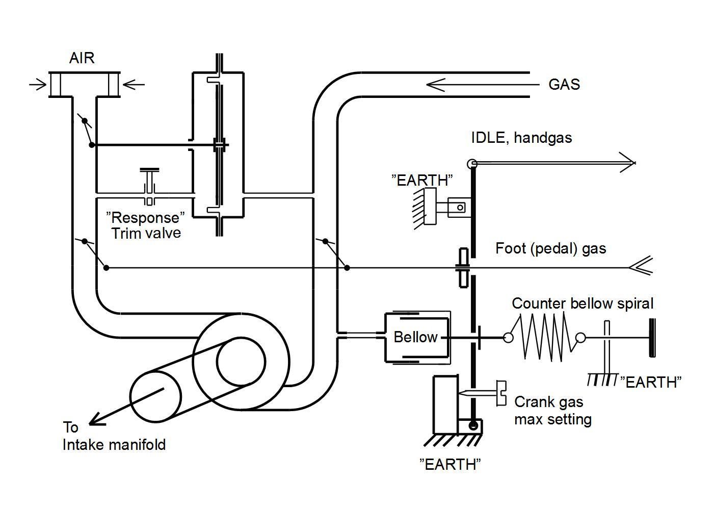
That’s a vacuum bellows which governs the vacuum at cranking. Works like this:
Engine off, bellows relaxed, spring pulls bellows open. No pressure on gas pedal, throttle is open 0%.
Engine cranking begins, low vacuum pulls on bellows. Begins to open throttle when sufficient vacuum exists.
Because of the built up vacuum, equal quantities of gas and air are metered in past the twin flaps. Engine starts instantly on correct mixture.
Engine running produces lots of vacuum, draws hard on bellows, overcoming spring. Pushes on throttle more, raising idle. Continues to raise idle until the stop screw is met. This determines your “low idle”
The hand idle is completely independent and works like Wayne’s string idle control. It must be completely relaxed for the vacuum bellows to work at cranking. When the engine is running and needs to idle higher, this is adjusted to produce a higher speed. Can be a crude cruise control as well.
3 Likes
03.08.15
Hi, Andy!
There is plenty of time to evaporate gasoline-gas squirted from a carburettor, before attempting to crank it going. Especially as cold.
The throttle can — and is set for the air needed for a comfortable idle.
With woodgas there is no evaporation; gas and air have to FLOW together in correct proportions FROM the FIRST crank sucking!
The only way to avoid random, disproportioned mixes to emerge is to start from no-flow vacuum.
With a vacuum of 1 to 3’ (feet) of water, the identically opening flap-gaps are
dispensing equal flows of gas and air!
The ”bellow” is overcomming the set spring tension when the cranking acheives the desired vacuum. Then first, the flap-gaps start opening and a balance between pumping and flow is established.
The stop screw is there to avoid fatal rushing, as the vacuum jumps about 5 times higher when the motor fires!
Do not use handgas/idle during cranking, or you ruin the needed vacuum!
Ask more if this does not cover what is important or has been overlooked!
Max
2 Likes
Good stuff Max!!!
I like pictures 
HI MAX,has this unit been been tested,or set up being used on truck size motor.and if you could name the componets,i could understand it better,I dont know the simbols, the auto adjust mixer would be nice too acomplish at some point.THANKS
Yes, this setup has been used on Dutch John’s Volvo and truck. I don’t believe he had the startup bellows however.
05.08.15
Hi, Kevin!
”EARTH” is used in electrical schemes, but also in old mechanical sketches.
The meaning is probably selfexplanatory… riggid, uncompromising, permanent ground for attatchment.
This dispensing technique with balanced flows, first developed in Sweden around 1920+ came to my awareness about 1984, when lending the book GENGAS.
Still, inspired by respiratory technics I had my own version tested 2 years earlier…
In Germany 2004, I had an opportunity to apply this system on a big former Diesel motor 6 cylinder Valmet, rebuilt in Holland for natural gas.
Driving a 85kW 3phase generator.
It was a glorious day as a 15 person international crowd looked on the very first start on woodgas.
Instant start on woodgas, and the landlady served the whole gang with
Champagne!
That was a bit before DJ started to apply this system…
Here follows a new copy of the scheme with filled-in designations…
Max
Thanks max ,You have an interesting history with wood gas,i copyed both pics too my computor for lator when i get time too spend on automatings the mix , Thanks for shareing your ideas,When Chris Saenz gets it working and simple fied on parts too use, maybe YOU guys can post an easy for dummys too build plans cheap, THANKS
Little update on this. I’ve redone the diapraghm material a couple times. Currently I’m using heavy-duty lawn trash bag material. I think it’s 2 mil.
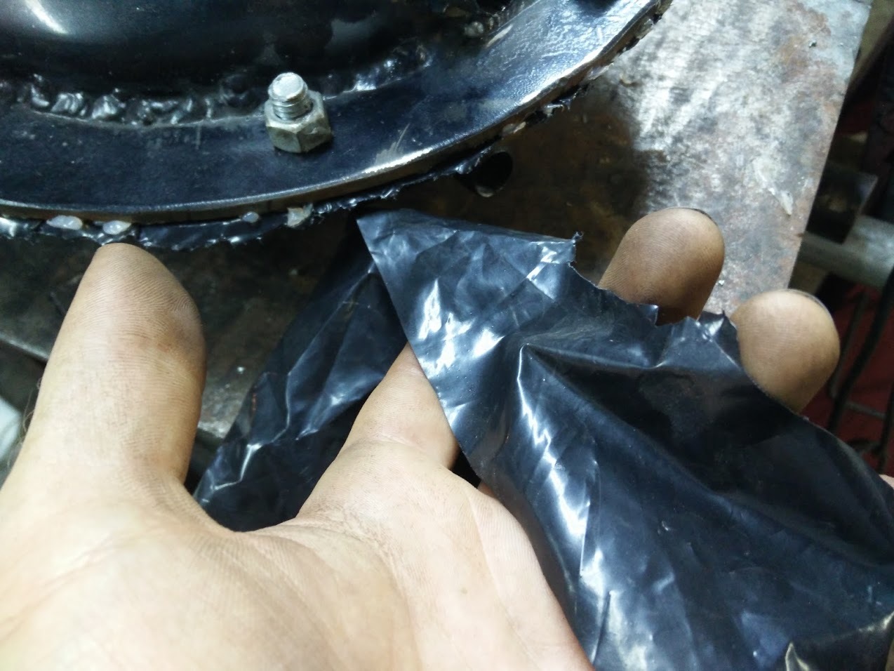
I set up a jig to hold the diapragm upright, for bench testing. The loop is a water manometer, which will tell me how much suction I’m using to drive the valve.

The less suction it needs, the better. The target has been 1/2" of water column.
I tested the movement using a cheap fan, which only puts out volume and not pressure. Still, it was able to “blow” the valve open and closed - I measured this at only 3/16" WC.
Video:

11 Likes
Good evening Chris saenz, nice project,interesting. hope it works good when done, I gess it will help a lot.Thanks for tackeling the add on project.
Would it be possible to repurpose the old cruise control vacuum modules for this?
Hi, Matt!
Basically a diaphragm with one side open to the air and the other one closed and connected to some other ”vessel” will do some job based on a pressure difference to the atmosphere…
Active diaphragm area times the pressure difference gives the power…
If jou are going to ”destroy” the speed controller you have a good ”bellow” to set the cranking vacuum against a suitably strong spiral.
Max
Yeah that is what I was thinking they are already made and probably could be found in the junk yards. If these older ones all gone then maybe a brake booster could be modified. Might save some time and effort 
1 Like
Brake boosters are big and cumbersome. A diameter of 3" might be big enough to handle the flap mechanisms; it depends on the vacuum you can crank and how much you are satisfied with.
Setting the “let in” vacuum at about half of what the cranking can reach maximally with EVERY route closed seems to cover all situations reasonably?
Crankcase ventilation has to be stopped under ANY of the flaps, including the gasoline-air route. Crankcase ventilation has to be set abowe any flap!
Max
1 Like
Then there are bellow hoses that can be adopted and put loosely in a protecting tube…
Max
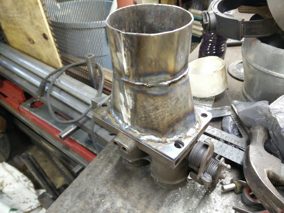
Progress report. Today I’ve been working on the “twin flaps” aka the woodgas throttle. They must be distinct yet identical passages, one for air, one for gas. I’m using a Ford throttle body from a 90’s F-series truck:
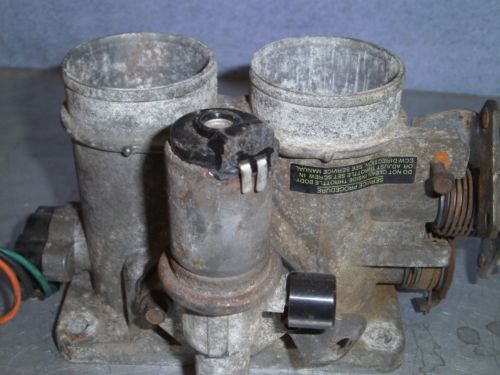
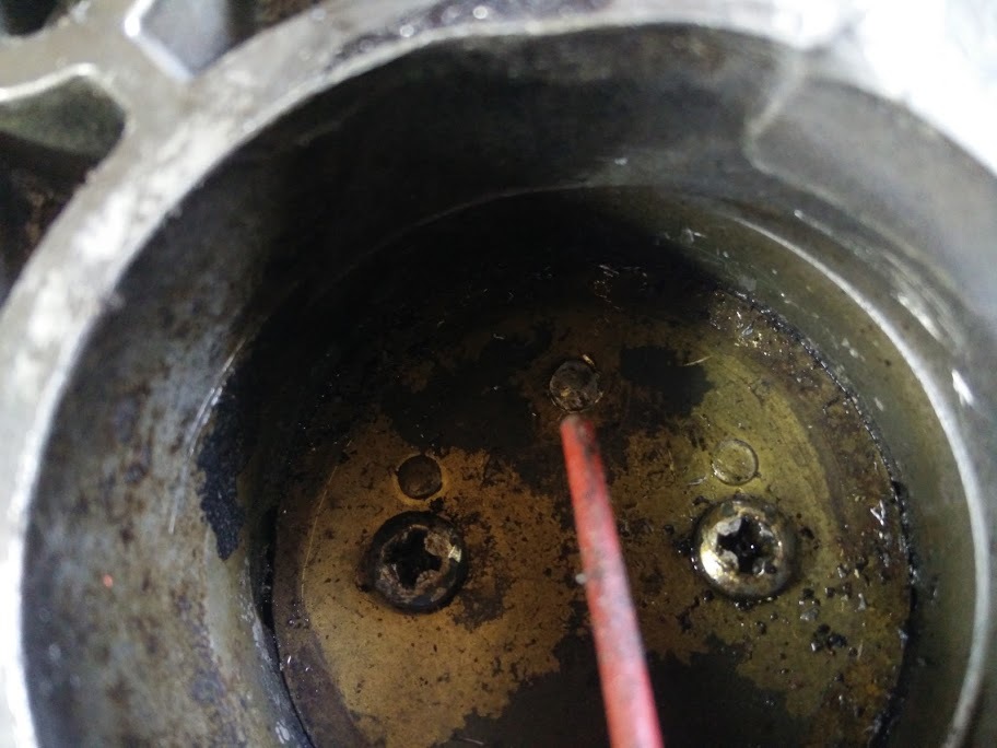
First I plugged off the idle passageways. JB Weld in the center area:
A rivet, to close up a hole in the throttle plate:
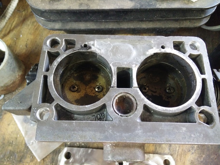
Now for the output side. Max says it needs to swirl some so it mixes together, so I’ve made some deflectors to get it spinning:
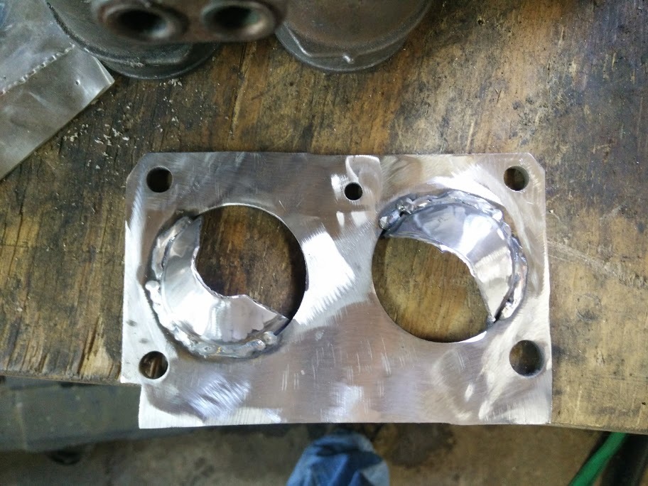
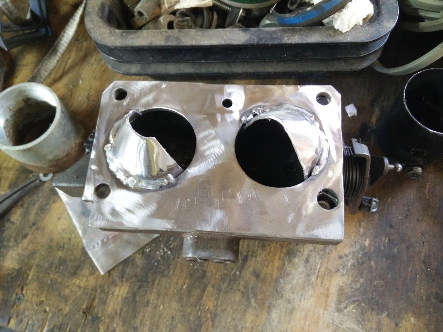
Then I need to merge the gas and air:
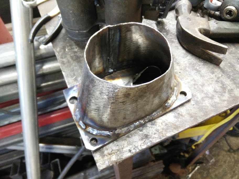
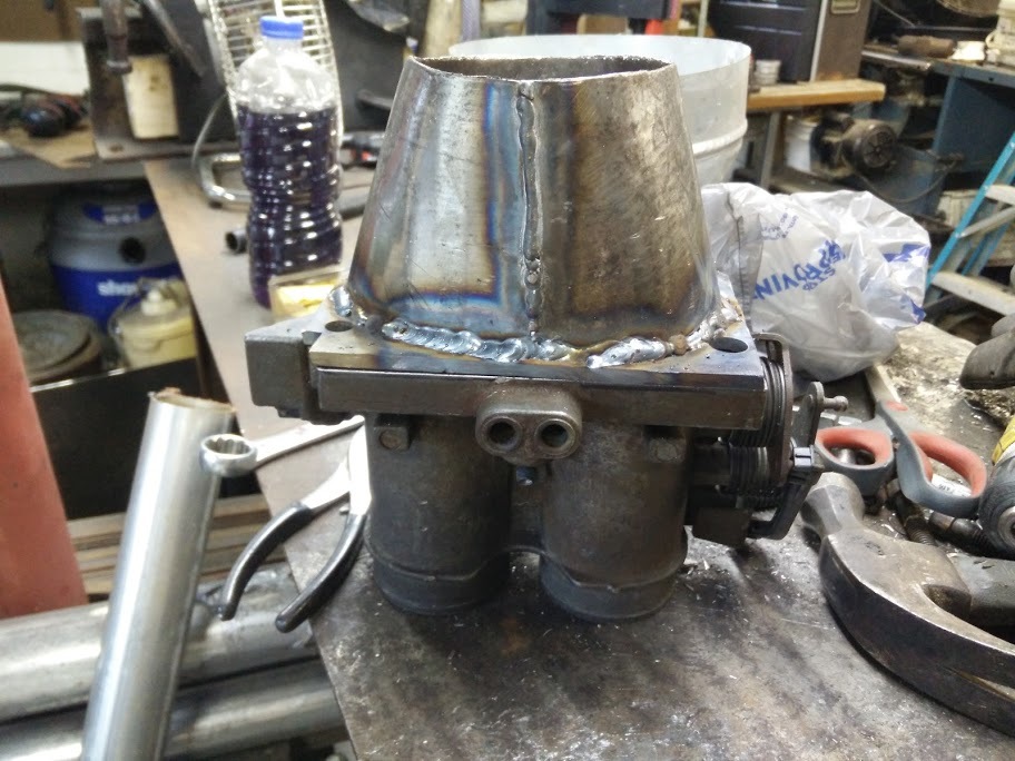
And then a fitting for 3" PVC, something I can clamp a Fernco on to:
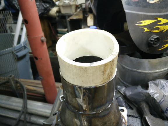
I have tested the airflow with a shopvac, there is lots of swirling happening. It will spin a pencil around pretty quick. I may at some point add an inline swirler, but I’m going to start with it as-is, I think it’ll work fine.
2 Likes
I see the first picture Chris but the rest show as round circles with a horizontal slot in the center. Are these supposed to be that way?
All fixed, thanks Don.
“No: 7” is still missing…
Hope the “scoops” are identical and not restrictve. Looking impressive!
Max
1 Like