I probably underestimates the extent of this work
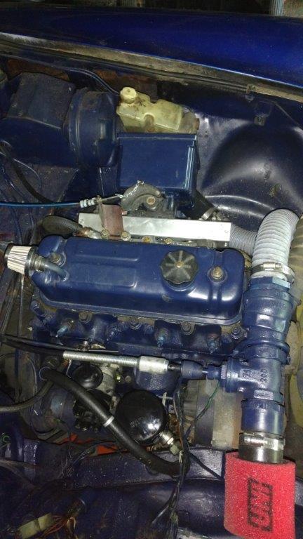
Should we separate the exhaust manifold of the intake manifold?
Rebuild the exhaust manifold with the piece of origin and build a new intake manifold?
I probably underestimates the extent of this work
Should we separate the exhaust manifold of the intake manifold?
Rebuild the exhaust manifold with the piece of origin and build a new intake manifold?
Using the existing exhaust and fabricating a new intake sounds right.without looking at it. After separating, you may be able to wrap the exhaust manifold with header insulation or something else to keep your intake cool. Can you post some more pictures? I can’t even tell how many cylinders it has. Are you doing the welding yourself? If not, let your welding guy look at it to get a second opinion.
I understand better the challenge now
First, I will try to find a spare manifold (parts of these engines are rare)
I’m not good welder .I entrust this work to a welder friends
I’ll let you know in due course
thank you for the information
Thierry
Won’t have any problems at all with adapting your tractor.
Triguax, If you are going to work with this sort of stuff you really should start thinking about learning to weld. If I were you I would start out leaning how to braze. It is not hard to do and it it is very versatile compared to the different types of welding… You can braze thin and thick metals of all types ( almost anything except aluminum. ) I have brazed many exhaust manifolds ( cast iron ) and it stands up to the heat just fine. I have all the welding stuff including a oxygen/ acetylene which is common for brazing, but for light gage stuff you might look into using MAP gas. It comes in little tanks like butane torches. Yes you may have a good welder friend who is doing your work and you don’t mind waiting for it, but there is a certain gratification, in doing things yourself, as I’m sure you already know. TomC
absolutely agree with you Tom. But said here: “the world s’ is not built in a day” I try every day to improve myself but I do not progressing as fast as I would like
So I delegate some contract to another
Thierry
The sweet wife says no more work on the MG until the second week of july when company leaves. But I managed to steal a little time to put together two weights that will keep the charcoal moving down and inward as I drive. I hope this eliminates the hollow cone and bridging in the middle that can occur where the charcoal is being consumed.
Looking great! The way it looks like this might work great!
I adopted your nozzle poaker on my sistem. l havent cleaned the slag yet ever since and l think i am not going to until something stops working as it shuld.
Thanks for the encouragement. I’m glad the poker idea is working. I can’t wait to get back to work on this baby.
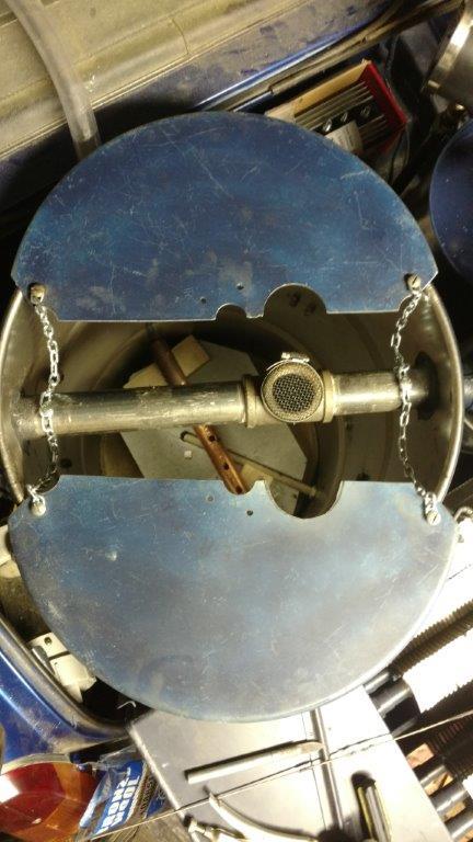
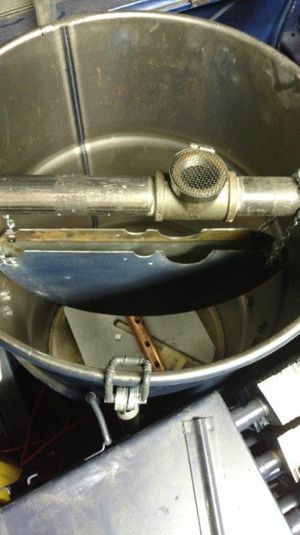
A little update. Almost ready to fire up. Hopefully by July 30. Upper left is air inlet with bronze wool flame arrestor and EGR. Just to the right are the terminals for the thermocouple. Wingnut and disc is the cyclone cleanout. Red tube is Cherry Bomb glass-pack muffler with insulating wrap to protect PVC exiting filter. Muffler runs parallel to bumper.
Nice progrss!! the flexible tube on the intake is exhaust return? how do you plan to meter it?
Once the gate valve (visible in photo) is set, the exhaust is more or less self metered. As load increases, exhaust increases to keep the relative ratio of exhaust to air fairly constant. I suspect that this EGR circuit will be unnecessary when adding water mist to the other end of the nozzle. If I find that I want to use EGR to control reaction temps in stop and go traffic then transition to water for highway speeds, I may add an electric window motor to the EGR valve. Of course your experience has shown that neither are necessary if we are comfortable with a hotter reaction zone.
If I don’t need the EGR, perhaps I can remove the flex pipe and use the valve to to tune the exhaust sound just for fun? The water mist pump is controlled by PWM from driver’s seat. I look forward to playing with these variables.
I’m pretty confident that I will have adequate power, but if more is needed for hills or passing or showing off, alcohol sprayed into the intake manifold while adjusting the air mixture (alcohol AFR is 7:1) can theoretically give more power than gasoline.
What kind of water mist pump do you have in mind?
I think for highway speeds water injection is a must. I culdnt belive my self of the power water gas has in comparrason with gasoline. You too will be amazed  Great planing stay on corse and dont forget to post news!
Similar to this one:
I added a mister nozzle on a 4 inch piece of 1/8 inch pipe which passes through my bronze wool flame arrestor. Mister sprays through open shutoff valve below arrestor.
Is this made to run non stop or just occasionaly for short amount of time? l have a similar one (window washing pump) but am afrayd its gonna burn pumping non stop. l was thinking to use a aquaponic mister but dont know what kind of water outputs they produce.
Bruce beautiful building
I look forward to seeing your first test!

I’m hoping with use of a PWM that the pump will be operating with a lower (intermittent?) current and last much longer than with a physical restricting control valve and constant current. Perhaps someone has better info or experience?
Stunning ! I really cannot wait to see the first of many runs you will have on the lovely little girl .
well done Bruce , its just an amazing amount of thought and skill gone into this .
Dave
I think a pump controlled by a PWM will not build a uniform and constant pressure.
The pwm will create a variable volume flow
I already tested the pump with a mist nozzle and the PWM seems to work well for giving a consistent flow. I just don’t know if the pump will last long term.