From reading years ago I recall that there can be two types of flow through any conduit, laminar, and turbulent. The type of flow depends on diameter of conduit and the velocity of flow.
This predictable effect can also be used for cooling . I will have to find a source article I read that was directly about gasifier design parameters.
Tubing diameters depend on the gas quantity, but also on the temperature. In most tubing, we want a laminar flow (< 5 m/s). In some tubing we need a turbulent flow(> 6 m/s). Unfortunately turbulence raises the pressure drop in the system and reduces the filling degree and with that, engine power output.
To determine the tubing diameter, we first calculate the gas flow in liters per second. “We had that number already?!” you will notice; indeed, the quantity of cold gas. But since the gas is hot, an increase of volume occurs. We recalculate this flow using a conversion in Kelvin. 0 degrees Celsius are 273 Kelvin. 350 degrees Celsius are 273 + 350 = 623 Kelvin. 18.4 [l/s] at 350 degrees becomes:
Dutch John explains the flow characteristics on his site.
Problems with turbolent flow is it puts drag on the sistem. Superior otherwise.
Air/gas mix travels laminary usualy, so a way of mixing them better is supposed to have a effect on fuel efficiancy. I think the turbinator does a amazeing job at this.
But, isn’t gas mixing exactly the same technical issue you see in propane or natural gas powered vehicles? Their gas mixing systems seem to be very simple, incidental even. By the time the charge flows into the cylinder past the intake valve at almost supersonic speeds, surely it’s mixed?
If you don’t mind, I will give my two cents.
Yes, with turbulent flow, the resistance increases more compared to laminar. So only use turbulent, where it is needed, for example a cyclone.
And at a gas/air mixer. With bad mixers and inlet manifolds you can have the effect that one cylinder is lean, an other rich despite the overall mixture is right. Result is obvious: Less power.
So the turbinator does a good job here. Or every other device that leads to turbulent mixing flow. The greater pressure loss in the mixer is in most case better than the power loss of the engine due to bad mixing.
Of course only valid for multi-cylinder engines.
I have no experience with propane mixers, but keep in mind that here the gas/air ratio is differtent to woodgas.
You are rigth, but have to combine air and gas already evenly in the inlet manifold so that every cylinder gets the same ratio. THen the swirl of the inlet valve does a good job of mixing the air and gas molecules.
Til, l was thinking a while back if that effect is possible. I guess the tooned intake with intake tooning valve on my Chevy was doing a better jor with dispaching air/gas equaly to all cyls, compared to the “toilet syphone” intake nanifold l have on the MB
Speaking of wich, thanks guys for a ass kick, l realy shuld do something about the gas mixing manner. Its wery primitive right now.
IS FLOW IN A CYCLONE TURBULENT? I don’t know that you have to have continuous lineal flow for Laminar flow. As the flow goes around it can be laminar and as it goes up the outlet pipe it can be laminar. Probably when the gas does a 180 and heads up it might be for a moment turbulent.TomC
After about 100 miles on my Silica Gel, I weighed it to see how much moisture it had adsorbed. There was barely any difference in weight so I’m expecting a long and happy life before it needs to be “recharged” (dried out). I think I put in about 3 or 4 pounds of large packets.
Thank’s Gary, Kristijan, Allan and Tom for your kind words. I do my work as a service for the actual and future crew members of this site. Your words motivates me to keep doing it !!
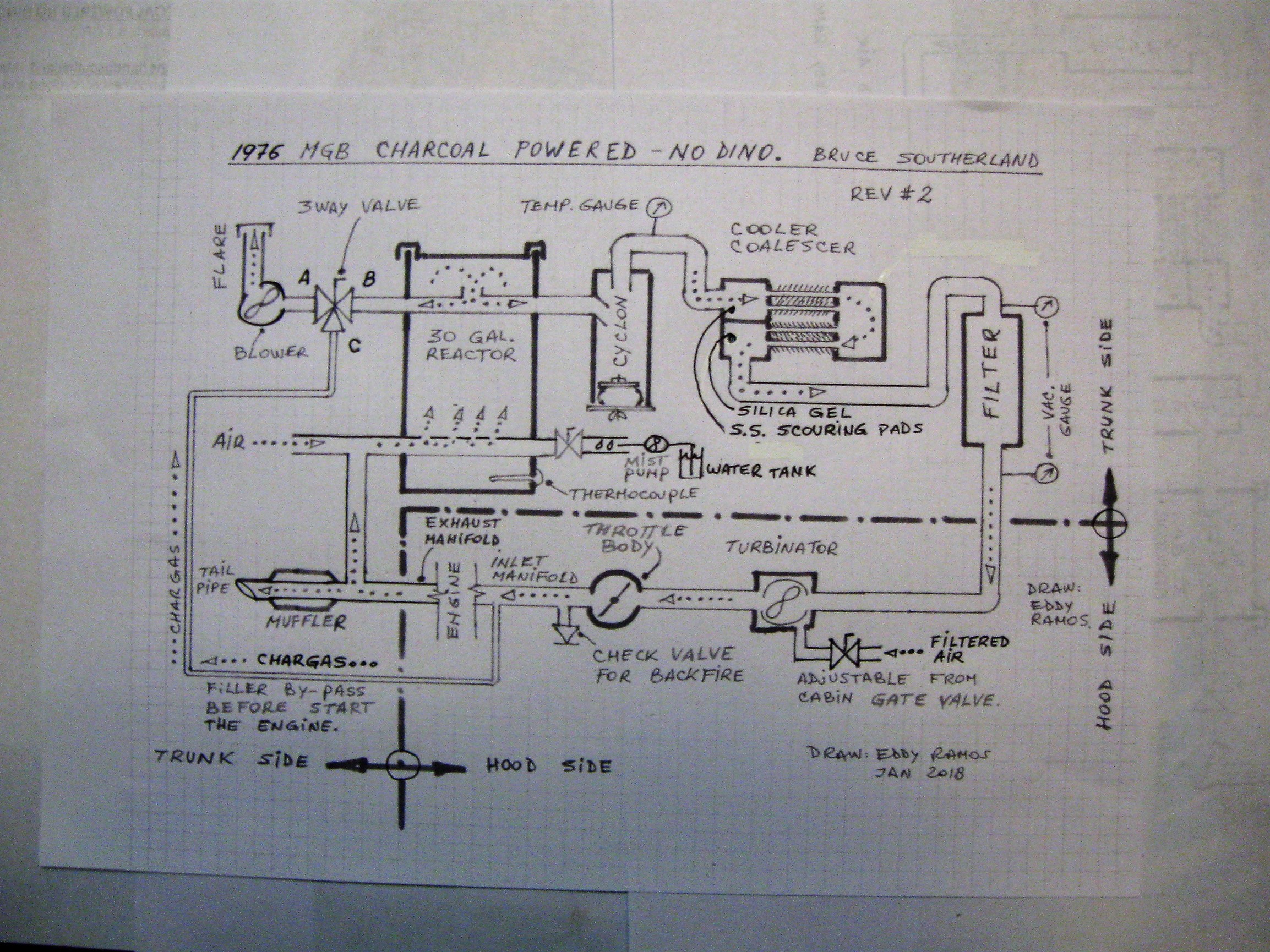
I can only make a sketch out from the videos made by the owners that are willing to share their work. I already made a sketch for Gary Gilmore Kahle’s, Don Mannes and now Bruce Southerland gasifier’s based on their videos.
Kristijan, I will be more tha happy to join a sketch group, please notice that it insumes a lot of time so it will great to have others to help on this project. Again it all depends on the good will of that owners that may be willing to share their work.
Thank’s again Bruce for your corrections. May be there are more people that I thought that appreciate your good will in sharing your work. Please find attached the Rev #2 drawing. Feel free to make any further comments.
Eddy, You’ve done it! Thank you so much for this great addition to this topic. Your beautiful work has also stimulated a good discussion.
I plan on taking the MGB to car shows this summer. I will be using your Skizz to help people understand the system.
I plan on having your diagram displayed on top of the reactor with a jar of charcoal and a jar of water sitting nearby. When I gather a crowd, I will explain that it runs on charcoal and water. I will then pop a piece of charcoal into my mouth, give it a chew then wash it down with water. That ought to make the greenies happy.
That (wood) be a ruff chew for all the wood gasifiers to demonstrate, even with the water to get it down.
Here in Washington The Evergreen State I think greenies tree huggers would try to stop me from driving my truck if I started to show it off. Even though I’m a tree hugger with the right frame in mind about it. GROW THEM, USE THEM, PLANT 100 MORE THEN THE ONE YOU HARVESTED.
Bob
Hi Bruce. Thank’s for your compliments but sure your are the BIG piece of this puzzle.
Regarding using my Skizz you are more than welcome. I will greately appreciate if on some little corner it shows that I draw it from Argentina. Some peolple will wonder how come somebody from so far has did it, this will be an opportunity to explain that this a world wide team working thru the web.
I have a last issue: Where the flame arrestor goes exactly??
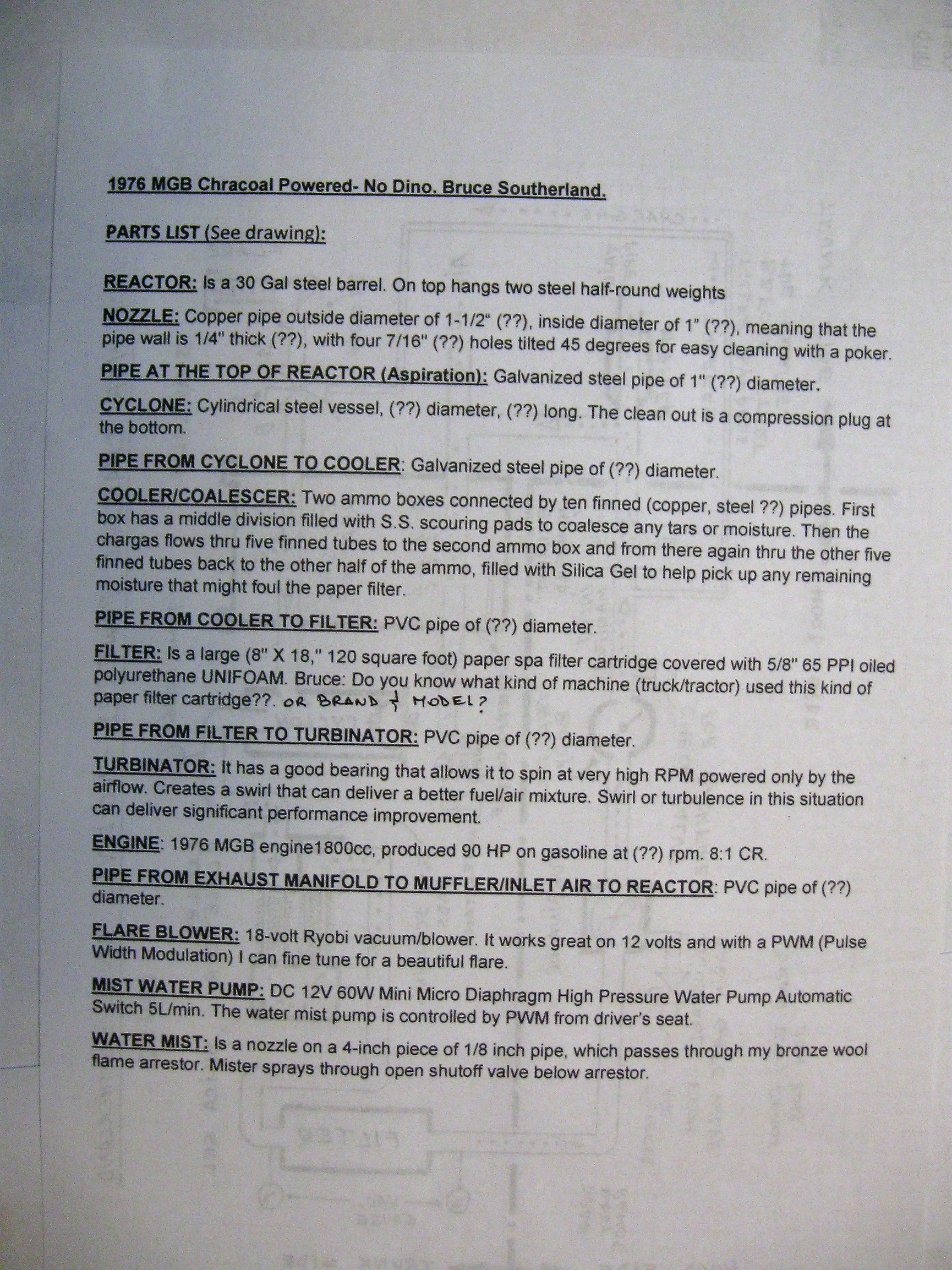
Since I had some spare time I decided to start making the PART LIST of this thread.
Bruce, please find attached the list and check it out. Again, your are more than welcome, if you wish, to make any corrections/suggestion to it.
One question: What brand and model is the paper filter cartdrige you use in the filter??
Truly yours.
Hi Eddy,
I will gladly give you credit for the drawing and give credit to our whole worldwide DOW community for nurturing me toward this end.
I have bronze wool flame arrestors on both air inlets to the nozzle. The one on the bumper side is removable for lighting and cleaning the nozzle. A thin pipe with a misting orifice passes through the bronze wool on the other side.
Hi Jeff.
Again, I will gradely help you do some sketchs, but I don’t think this is the right topic. Please don’t get me wrong. You should creat your own topic “Jeff’s producer”, where you can upload pictures, videos, hand drawings, part list, comments, etc. Please let me know what you have decided.
Truly yours.
Eddy