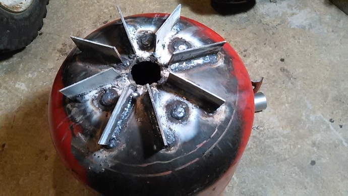
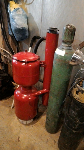
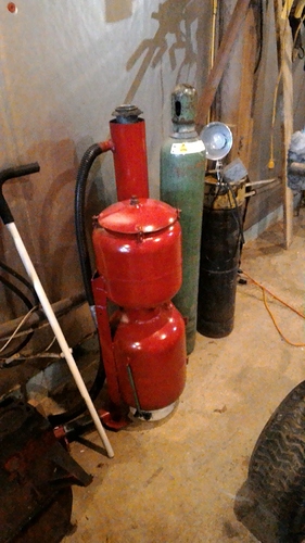
Ahhh! Now I see it. The picture of them on the garage floor has them “back to back” and upside down, correct?
You got it, Brian. I had to grind the bottom of the bolts because they hit the bottom of the pan.
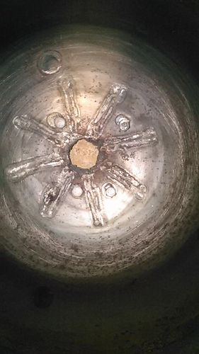
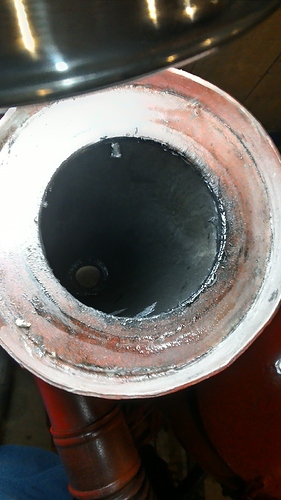
Some refractory mix’s will not stick to metal but furnace cement sticks nicely to metal and my guess is that the refractory will bond some to the furnace cement. So I first apply furnace cement to the bottom of the tank then sand it a bit to roughen the surface some. Before that I use heat to help remove some of the surface oil on the bottom of the tank plus sand paper and a solvent like Colmen cook stove fuel. Most of my tanks had some kind of oil in them. I also drill four holes in the tank and install four bolts that stand up inside the tank. This gives something for the refractory to hold on to. The last step is to cast the refractory.
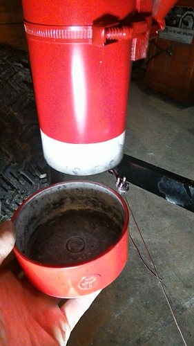
Inside.
That’s the only photos that I have.
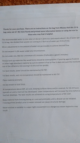
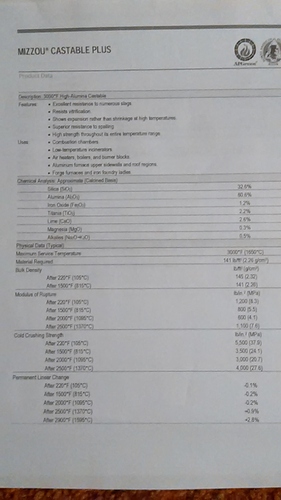
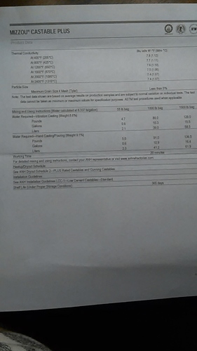
Next I’ll dig up what refractory I used.
This is the last refractory I used. Only time will tell how it will hold up.
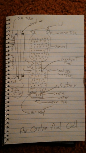
Sorry, kind of hard to read. You might have to down load it to read it.
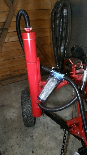
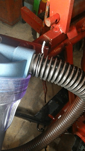
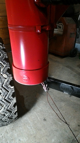
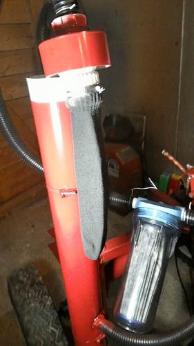
I should also place the filter photos here. Mostly slip fit thin wall PVC. Subpump hose snugged up with fence wire. Cotton sock material poor choice because it can stretch and open up the weave. Will replace some day. Top and bottom easy slip fit.
I’ve been wanting to Bri g this up for at least a year now and now I have a bit of time. In one of those Tom Reed books it talked about gasifier air ratio, or something like that. I always wondered how in the world could that be controlled. I am not saying this is how it is done but here is my story.
I always made provisions for easy air intake into the humidifier pan. The last version I simplified it by using four wire spacers that made a space between the pan and the bottom of the producer. About a year or longer ago I forgot to install the wire spacers so the air was in shut down mode. The engine seemed to run better that day and when it was time to shut it down I discovered the air inlet was shut off. Of course I’m sure some air can leak by but I can not see any gap!
In the past I always found improved performance by reducing restriction. Allow the engine to breath easier. This time it seems the opposite. Could it be possible that it is best to reduce restriction right up to where all the action is, the reduction area but then choke the intake down a bit to make a small amount of vacuum when the gas is created??
Thanks for sharing this experience. This should be easy to test for those of us using horizontal pipes to feed our tuyeres. Just install a gate valve and play with the combustion air and EGR settings (and H2O drip) for optimum power under load.
My grate is about 2" diameter so that would be like a 2" nozzle. But I also have an air inlet. So your small nozzle might be like my choked air inlet. So, the question then becomes, is it higher air velocity or vacuum at the site of gas generation that helps.
So a test with a nozzle producer might be to start with a very large nozzle ( too large) then see what happens when the choke off valve starts closing.
It ran fine before the air was choked but seemed to run a bit better when choked.
Maybe the vacuum makes more steam.
Good thought. The improvement may be from superficial velocity, but wouldn’t the restricted higher speed air slow down when it passed into the 2 inch diameter area that feeds the grate? Perhaps inserting smaller diameter pipes into our nozzles or grate tubes might be a better test of the superficial velocity theory?
That is the common idea. But what if it was because of vacuum at the site of gas generation. If air blown gasifier performs the same as a suction gasifier I would have to say no.
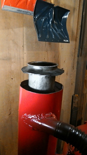
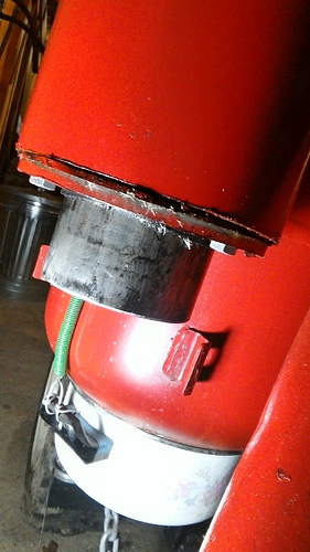
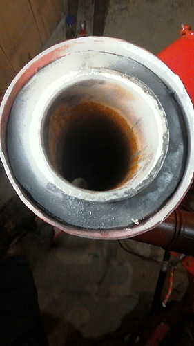
Since the gas is removed as fast as possible without traveling through the charcoal fuel supply a gas cooler is used. It is a pipe inside of a pipe with tangent inlet and outlet on the outside pipe.
Hmm, I forgot to take a photo of the complete cooler. I’ll do that later.
This is the inside pipe. I like to oil it with canola oil at least at the bottom so that it slips into the seal made from tractor inter tube.
Top of inside tube. I hammered the end over on an anvil (lip) so that the top seal, cut from an inter tube, does not slip off.
Pipe being installed, almost installed.
bottom with inside pipe installed.
The bottom seal.
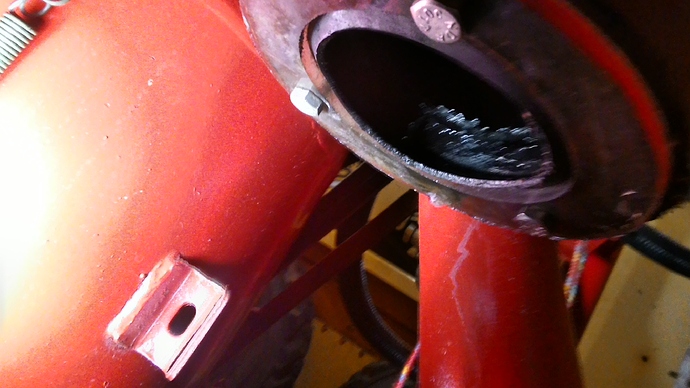
The top outside pipe seal mating surface.
the top with inside pipe installed.
Hi Jeff
I think Koen says that the gas produced in negative pressure is better than the gas produced in positive
pressure!:thinking
Thierry:
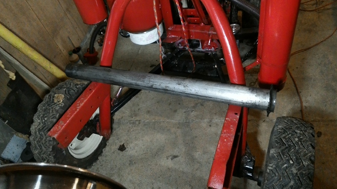
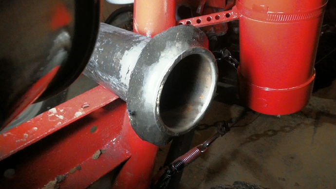
Just a couple photos of a lonely producer sitting in the shop, wondering what it will be doing in the spring.
Jeff,
Is that a cyclone with filter above? I like it!
Bruce, you nailed it right between the eyes. It is a thermal-cyclonic-transformation-fuel-separator.
Jeff, does the cooler tube also work as a spin filter and collect char dust in the bottom with the water condensation?
Bob
Hi Bob, Water will collect on the bottom, sometimes, Dust and condensed water collects on the walls but not as much as one would think. Well, one time when I over sucked with the starter fan I found an amount on the bottom with water.
what level of efficiency do you opt for with this equipment?
It is different than I thought. I see that it is more of a cooler than a cyclone. I didn’t realize that the center tube was a passage for cooling air. I thought you had a cyclone with a sock filter chamber attached to the cyclone outlet pipe.
