I have a small engine I want to use this gasifier on. As you see, I have constructed twin radiators for it. The other one will be mounted on the other side. Can I connect this right after the reactor or should it go through a cyclone filter first? Also, I want to change my burn tube from 4" to 8". What are the calculations I need to reduce this down to? What size air inlets do I need to make? Will the air jets go right above the reduction? If so, how far?

Hi BillS
Well the easiest to answer first: then on to the more difficult.
The ASH cyclone SEPARATOR will always go as close coupled to the hearth produced gas chamber as closely as possible before anything else.
I prefer these to still remain somewhat hot so the ash drop out doesn’t muck out from woodgas condensate dropping out here.
Some; do get some actual coarse soots removal here also depending on the actual woodfuel used, the gasifer, the engine gas draw rate AND in my expereince how much the woodgas is allowed to cool here.
Air inlet jets NEVER go in just above the thermal/chemical Reduction zone.
First the air is contolled let in to OXIDIZE some of the premade charcoal to produce ALL of the internal needed HEATs.
Then some of this created heat is allowed to rise up to pyrolize cook out of the fuel wood the moistures and the fuel wood volatile componets. This will leave the then dried out, volitals freed up, fuelwood as glowing HOT CHAR cores.
The majorty of the super hot oxidization zone created HEAT and remaining of controlled let in oxegen will then break down these heat released very long chained complex wood volatiles into now very HOT Shorter Chained Gases.
These now HOT internal gases will be the gasifier internal fuel gasses to then be drawn down along with the gravity downward falling HOT CHAR chunks to make the lower thermal/chemical Reduction zone. You actual desired motor fuel gases are produced here in this termal/chemocal Reduction zone.
So; you need some space separation from the nozzle jets at the air beginning entry through an Oxidization area to the actual thermal/cnemical Reduction zone for the distance, and flow time, for the oxidization produced heat to drive these initial physical and chemical changes to occur.
Any let-in air nozzle oxegen NOT all oxidization zone USED UP that makes it down into the thermal/chemical Reduction zone will turn it into a char burning up oxidization process instead!
You will turn off your thermal/chemical Reductionand then NOT Make ANY engine fuel gasses.
Be also Oxidizing there now and just make lots of metals killing lower hearth heat.
There is your clue - too HOT of lower hearth heat and you are no longer making Reduced motor fuel gases.
You are now no longer a motor fuel gasifier. Just an overcomplicated char brazier all buttoned up.
I am confused by your wanting to “change my burn tube from 4” to 8"; then say calculations to “reduce this down to”. You just mean recalculate internal volumns and distance proportions, right?
I personally class woodgasifer hearths many functional ways depending what I have to work with and what I’m tring to achieve.
So what is your engine size, engine type and intended RPM and loading useage? Just rough ideas on this. We need to roughly guess-ti-mate the amount of woodgas you will need to produce. No need or use for precise calculations on this. An engine running unloaded to fully loaded will have a minimum of 10 to 1 of actual air and fuels flows needed to supply.
Yep. Yep. There ARE calculators and graphs for this that will get you close for so call Imbert types meaning: High Velosity, Small Internal Volumn Types.
Then calculators and graphs for FEMA types meaning: Low Velosity, Large Internal volumn types.
Neither of these worked-up info base sources account for the very real operational differences in fuel wood species of Volitials vs Carbon (char) vs Ash ratios; air density as affected by altutude and mosture content; heat loses out the gasifier jackets; and many other real world gasifier challenges.
These maths were NOT rigid “Laws” calculated. But actually derived from found to be workable parameters out of many different built up gasifiers. Using them is only a starting point. Many excellant gasifier being used by individuals with great suscess to turn Thier wood inrto motor fuel gases for Thier engine under Thier local conditions that these math bases would say are, “impossible”. Well as I said a LOT left out of these maths.
So just what IS your fuelwood species? And how are you processing it for your gasifer use? Chunked? Chipped? Pellets?
These questions will help narrow down the dimentioning advice to start you out with to achieve your desired results. You’ll aways have to fine tune it in afterward.
Regards
Steve Unruh
1 Like
Thanks for your response Steve.
I’m still new at all the lingo and common understanding on this site. So I didn’t quite understand everything your wrote.
I will answer the easy questions first. I have a 13hp Honda that runs at 3500rpm. I have a lot of Oak available to me. I found with running a mixture of wood chips and chunks, I received better performance. There may be times I run one or the other? When I ran just chips in a 4" tube, I needed to tend to it a lot. I would like to have 3-4 hours of fuel in the gasifier if that is even reasonable.
My thoughts were to go to an 8" tube with a 4"restrictor plate. If I were to do that, I wouldn’t know where to locate the air jets or even how the reduction zone should be set up. How does one calculate how much air and how many jets are needed? The air jets I made were just a random guess. But it worked.
I’m also guessing my cyclone filter is way over-sized for the unit I have. Are there certain specifications for these as well?
I appreciate any insight I can get on this.
Bill Schiller
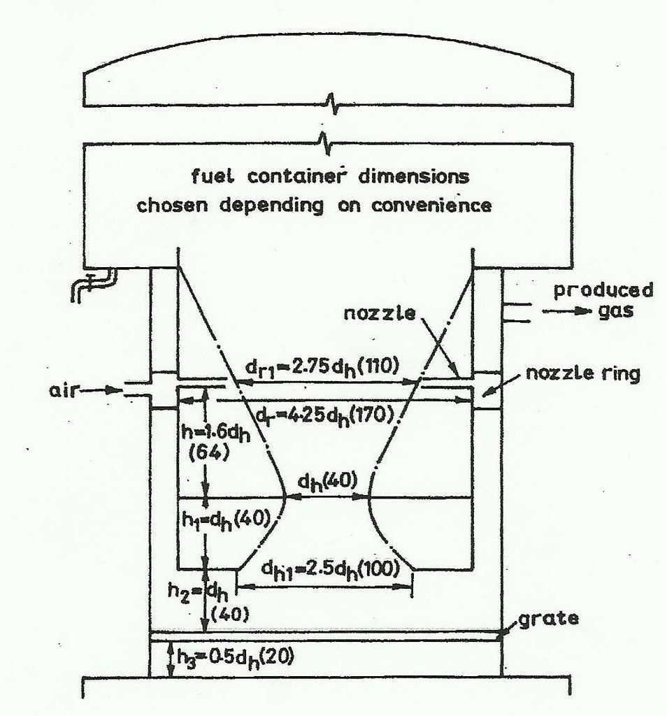
what type of internals are you currently using? is it anything like this?
I’d say 4 inch restriction would be on the large size for a 13 hp engine…
1 Like
Good Morning
ArvidO. thanks for putting up the graphic of an hourglass High Velocity, Small Zones Volumn system.
Ha! Not your’s, so I hope you’ll not be offended if I criticize this system type some.
And I do hope you will jump in with your more extensive chipped fuel experiences to help on that fuel type because that is some of what Bill wants to use.
BillS. from your information now I’d say Good, Good, Good, and not-so-good; and even bad.
I’ll still be making some assumptions. So jump in and correct because it will make a difference.
3600 RPM running so I’ll assume you are 60 herz AC generating.
Even better GOOD is I assume from your other topics posts you have actually been able to get your elecrical generator engine running and generate with your woodgas.
IF SO: THIS IS YOUR BEST GUIDELINES TO WORK FROM.
Means Your current air nozzles airflow rate is correct for YOUR loaded engine fuelgas draw with YOUR current hearth built system on YOUR fuelwood.
Increase your fire tube from 4 inches to 8 inches will increase it’s internal volumn and reactions distances.
If you just want to go for longer running time on a High Velosity, Small Zones Volumn System like Arvid put up; you put your additional running time fuel ABOVE the hearth with NO hearth change dimensions to an already functioning hearth.
On a Slow gases Velosity, Large Zones Volumn ssystem like the WK or others you do the same in storing more ready fuel wood ABOVE the working hearth.
These later being much larger and more open in the actual hearth area it is much easier to do above fuel storage with much less fuel particle hanging up and tar glue bridge jamming to have the wood fuel consitently feed down than with the smaller diameter volumn system types with narrowing necks.
In the High Velosity, SMALL ZONES VOLUMN systems everything from the fuel particles flowing down; the internal gasses and char flowing down through the hearth core; to motor fuel gases flow down and out through the grate grid ALL must ALL be kept flowing quickly and consistently with NO Stoppages of ANYTHING.
These are very much “Just-In-Time” internally replenishing systems from one internal step to the next.
The Slow Velosity, Large Zones Internal Volumn system hold a lot more internal Reserves of gasifer internal “fuels” and heats so give you much more time before a flow problem developes. And then much more time to detect flow stoppages and do something about it.
The 3rd GOOD. I finally saw that in your picture that your current cyclone IS Already close coupled to your produced gasses out jacket.
Your are too big to work properly internally.
The guy with the best small engine cyclone making and dimentioning is friend Dutch John as he shows on his web site: www.woodgas.nl in the MicroGasifers section. Look at his DJ-3 also Honda engine/generator system pictures.
Look at how he made up three paralleled cyclones from piping. Use his generated kW/el numbers in comparision to yours and upsize/down size his paralleled cyclones systems to match your needs.
Cyclones NEED gases flow drawn through Spinning Internal Speeded UP gases flows to work well.
It is this spin flinging that separates out the heavier solids particles of ash and heavier soots from the gasses flow.
The not-so-good to the bad. Your oak wood fuel.
RAW oak has a nasty habit of corroding out badly gasifier systems metals as they learned all too well back in the 1940’s.
WE “moderns” are redicovering this now.
They solved this by not using rarerto them oak wood fuel and then just using more common to them confers and semi-hardwoods fuelwoods like birch.
You must system woodfuel with what you got. Otherwise what’s the point of it, eh?
I’m assuming with your chipping you are talking about raw wood oak. Keep following the work of Carl Zinn here with his oak mill fuel wood in his vehicle to see how he evolves work-a-rounds this oak corrosion problem.
If your went with a 4" to 8" fire tube change even with a same/same choker restiction you WILL be turning yours into a Larger Zones Volumn system. With the increased internal distances and increased amount of internal chunks AT THE SAME ENGINE DRAWN GASES FLOW RATES internal gases will flow slower.
The slower gases flows means to maintain the same now needed proven amount of air oxegen into the system then you Would have to Increase the air nozzle openings to get in the same numbers of actual air/oxegen molocules flowing in at the same time frame.
The MORE the primary air is pre-heated also the larger the air nozzles must be to get the same numbers of then actual now wider apart spaced air molocules into the system in the same time frame.
See now why a sea-level cool dense air fellow will curse the air nozzle recommendations of a Denver High cold now dry 5,000 foot fellow for air nozzles??
I do NOT live where you do.
I do not have your same fuel woods.
Now on the “make fuel container to convinece”, " make the hopper as large as you like" I’ll call Foul! Wrong! to ANYBODY as far as raw wood fuel gasifiers.
Sure. Sure. Kiln dry and desert 1000 hour sun dried out picked up wood m-a-y-b-e.
And when you perfectly “dry” fuel runs out and you then have to fall back to winter wet fuel wood??
These fellows recommending this “make large” fuel hoopers are also the ones with notorious (or silently hidden) fuel bridging problems!
Heres what I’ve found from the very first raw wood fuelded gasifer I operated back in 2008 to the most current:
the MORE raw fuel wood inside being heated up - the MORE fuel wood water you have to then deal with.
What a wonderful experence that was back on that cold/cool early variable thunderstorm Spring day in 2008.
Set up to operate with 20 minutes in-system ready fuel in the warming Sunbreaks - all worked fine.
Then Cloud bunched up with Febuary Cold rainfall falling directly on it with now cold wind though it would cool.
This would be thermal quenched it below good reactions levels and performance crash it.
Put the big hopper on it with now 2 hours worth of fuel wood at a normal here 25% moisture levels and even then in the dry sunbreaks it would thermal quench also and performnace crash even worse.
Once you exceed the available internal made HEATs abilty to vaporize and keep vaporized the fuel woods moisture . . . .
Or exceed the internal hopper condensate systems ability (or complete lack of!!) to remove out of system the wood bleeding out moisture . . .
you WILL thermal quench down the lower zones needed temperatures abilities to make good motor fuel gas. Period.
So with a GOOD working hearth the areas you have to really get good at for extended run times is first the hopper shape, form and moisture removal ability.
And then after the hearth the consumed char ash storage space.
AND in the actual hearth With a high ash hardwood fuel like your oak get really good on grate bar spacing/grate activity to keep the greater dense harwwod volumns of accumulating mineral ash exposed out from the Reduction CONSUMED up chars from flows clogging and choking down the whole system with ash clogged at the grate.
Gives you insight that fuelwood minerals “ash” base percentages are going to greatly affect system design and operating characteristics!
ALL of the publish graphs and charts based on “foreign” to me birch wood or European pinewood have been terrible references for use on my native Douglas Fir wood!!!
And this is WHY I an very shy giving you actual design numbers.
Instead DO GIVE you what to look for to achive Your results for You, and Your circumtances.
I’m shutting up now waiting for more of yours and others feedback.
For a working terminology key curser over the top of page “Learn” tab to dropdown the “Basics of Gasification”
Read Jim Masons excellent center of piece definations of Drying, Pyrolisis, Combustion (oxidization) and Reduction.
Want more; or different wording and I can expand out especially on the tricky all important thermal/chemical Reduction step.
Regards
Steve Unruh
My friend Steve, I put that pic up just for that reason…
Thank you for your response Steve.
Here is a drawing to show you why my gasifier works and doesn’t work. Clearly this setup was my interpretation of how a gasifer should be built. After getting my WK book, I see some things I can change. I initially thought the burn zone and the reduction zone were to not touch. That is why I welded a grate between the two zones. Could this be why I have a lot of moisture in my gas?
The 4" tube bridges and the wood doesn’t last very but 5 or 10 minutes. This is why I would like a bigger hopper. You obviously don’t think an 8" tube would be appropriate. What about a 6" tube? If I go with a bigger burn/hopper tube, do I keep the reduction tube at 4"?
I’m not sure what you mean by “thermal quench”. Does this mean the moisture from the wood drips down the sides and gets into the burn area?
Bill

Wow! I’ve never see this simple of a raw wood fueled gasifier that would actually make engine grade woodgas and run an engine without a VERY GOOD operator attached. You are just about close to the preverbal “able to making woodgas out of a piece of schedule 40 pipe”. Bill I am giving you as high of woodgassing compliment as we can give a fellow.
Your six equally spaced 1/4" air nozzles are spot on for my beginning recommendations to any doing small engine Small Internal Volumn raw wood gasifiers. You do not want to change this. Your distances proportions for internal small volumns system are close to mid-range proven usable. A crazy as your straight tube center may appear to many here it fits well into the range that the India/Mukunda 1985 to 1995 systems used.
I think we can tweek what you have up to 2 hour engine runs before having to make a complete redesigning rebuild.
I’d say you know now to pull out that center welded in grill grate and smooth things out to let the char chunks flow down through.
Your gases out moisture is most likely from both fuel wood moisture with maybe even some gas housing can burning up (combusting) of some of your Produced gases in the outer can. You are showing a lot of paint heat scorching there. The products of complete combusting are H2O water and carbon dioxide.
So let’s try increasing your REDUCTION zone heat charcoal stack volumn. Easiest way to do that will be to cut out your lower grate. Now make up a new at least 8" accross grate out of muti-stacked sections of oven/BBQ grill stock. Shoot for ~1/4 inch overlapped gapping. Now hang this grate to start with ~1 inch down from below the lower hearth tube opening. Use, say five chains anchored up on your lower 6" tube edge. Since you got this as a top drop in system then make up a forked rod to go all of the way up to the top up out the top through a tubing fitting with a slide fit to the rod metal ferrel. Put an ELL bent handle on the protruding rod end.
The dropped down char will now staok up on this grate and gasses will longer path flow down through, and edge out through a longer char Reduction flow pathway. REDUCTION actually means reducing down from the three molocule mid-system gases into shorter now two molecule gases. Absorbs a LOT of heat energy to do this. “Reduces” oxidation zone made temperaturs doing this. Size "reduces’ the cahr chuks doing this.
This change should give you a three-'fer advantage. Stronger more powerful motor fuel gases. Greatly reduce that outer can heat. Reduce “some” your produced gas moisture. You’ll always have some and learn to like it even for produced gasses soot washing out in the cooler section.
Hey over paint the outer can with some cheap rattle can paint please so we can temp monitor improvements. When the paint stops scorcing you will really know your internal processes are in good balances.
Yes my upper burn tube “hopper” in your case moisture dripping down will heat suck out in water vaporizing and quench down your temperatures at the air nozzles/ozidization zone. Ignore this for now. Pre-dry your fuel wood for now to minimize this.
For now the goal is to see what kinds of run time you can get out of just your internal upper fire tube fuel wood volumn.
ALWAYS PRE-CHARGE WITH CRUSHED WOODCHAR FROM THE GRATE TO A FEW INCHES ABOVE THE AIR NOZZLES.
Now when it wants to engine die out give the grate a shake and see of that will restore power from ash clogging building up.
Once you can get it to running useing up all of the internal fuel wood down to the nozzles - the engiene WILL die - then you’ll know how much above hearth hopper space you would keed for different engine running times.
With your current system as is you can just keep adding 4" pipe sections taller. Run it. Then you will probably start running into fuel wood particle hang ups. Beat the pipe with a wooden mallet to shake it down as you would suspect. Once you feel the hopper pipe tempertures dropping to hand held you can even switch to plastic hopper pipe.
The India users found at 10 feet they even no longer needed a top on the hopper then.
Ha! Ha! You will never want to do this. By the time you would be hitting these run hours I suspect you will be running into metals tube heat/erosion failures and wanting to then rebuild to larger diametes.
Look at what you have now as an operator teaching system.
If you do not burn it out you must be using good thick SS tubes. In that case you can really insulate it up to be able handle wetter fuel wood inputs and cumulative upper system moisture loads.
Regards
Steve Unruh
1 Like
Thanks Steve, this help out a lot! I will make those adjustments and get back to you. I want to change this out to SS. When I do, how thick would you suggest? I’m not sure what you mean by insulate.
Morning BillS
By stuffing the really, really needing to get, and keep HOT, center parts isolated down inside now a mearly hot produced gasses filled jacket/can you are already “insulating” - meaning conserving expensive to make wood heat energy.
For wood gasification stainless steel had some very postive benefits in corrosions and heat resistences; NO PITA rust shedding particles going downstream into everything like filters and expensive engines; nearly 100% gasifier been used metals re-salvaging and modifing capabilty.
Some Very negative problems using SS though:
Costs. In the really HOT center hearth pieces you WILL have to hand TIG weld to not have system heat weld failures and cracking/popping. SS heats and contracts at 3X the rate of carbon steels and cast irons - end up having to redesign a carbons steel prototype to acomodate for this or you WILL be buckling, jamming and gases leaking cracking. Any design deveoped around SS will NOT traslate back then into carbon steel 'cause SS has a much lower thermal trasfer rate - your carbon steel copy with heats bleed out and thermally crash - become a tar maker. SS coolers/filters need to be at least 20% oversized to allow for this lower heat out transfer - drives up their expenses to make. Worst of all - SS builds are very offputing to try and promote DIY wood gasification with. Most know that they cannot afford to do SS building and fabricating - turn, and walk away as too diffcult; thinking wood gasification “needs to be SS to work”.
For SS gasification materials experinced thickness recommendation look over Dutch Johns works:
www.woodgas.nl
He has built now with both ALL SS and mixes of SS and carbon steels.
Gas jacket cans/shells can be cooking pot/barrel/can 19-22 guage metal thin. That hearth core tube in my experence needs to be schedule 80 - call it 3/16" - 1/4" (3.5 - 5 mm) thick.
To insualte your current build you would wrap commercial kiln/furnace alumina-ceramic blanket or salvage self-cleaning oven blanket insulation around the lower reduction zone and the oxidization zone to ~2 inches above the nozzle levels.
Yours IS A DIRECT GLOWING HOT CHAR TO METALS SYSTEM. Centuries expereinces now of using air blown hot woodchar to hot work irons/steels and even smelt (melt) and pour cast with. Insulate wrap your current if carbon steel it will work Great for a very short time.Then all that heat held in a few very short hours later before metals failures. Direct contact INSULATED SS will buy you out a bit longer for 300-1000 hours in the direct HOT char contact areas. Much direct expereinces on this now.
Look back in Mr Waynes vehicle systems book and much of the genius is taking these concentrated metals destoying heats and distributing, spreading them out below metals failures levels, yet NOT not simply bleeding out and losing these heat energies but putting them back into the sysem for beneifits. AND DO THIS with DIY affordable common carbon steels and cast irons.
You will learn a lot about what your engine/gen and your oak fuelwoods are capable of by speeding up this training wheels system intil it’s wheels fly off.
Regards
Steve Unruh
Hey Steve,
Thanks for the info. Thank you for the compliment. I read somewhere a couple of months ago about preheating the air prior to the jets. This was the most economical and simplistic way I could come up with. I’m surprised I received a compliment, I thought I could only receive chuckles from my design. It does take a bit for the air to heat up, but when it does, I can tell the difference.
I’m excited to learn about the reduction zone and implementing your ideas (if I interpreted them correctly). First I am going to finish with my new cooling ideas. Here’s a picture. Let me know what you honestly think of the cyclones and radiators. I am quite certain the original cyclone filter was way to big? So now I am going with a dual exhaust and will join them back up on the other side of the gasifier when it’s complete. I will then run them through my hay filter before the air pump and engine. Hopefully this will provide a clean gas with less moisture.
I plan on buying a hydraulic pump for the 13hp engine. My thoughts are being able to run a wood chunker or splitter and chipper. I will also buy a generator head powered by a hydraulic motor.
It excites as to the possibilities the can be powered with wood. When I get this unit to it’s potential, I will then start on my truck. I have a lot of learning to acquire before that happens.
Bill Schiller

Good Morning BillS.
Good news on that engine NOT being locked into 3600 RPM direct coupled to make 60 cycle electricity. Now you can dial it in to wood gas operate at 2400 to 3000 RPM. Even though I have engine ran with woodgas up to 4200 RPM the air/gas control gets unstable under an engine load above ~3000 RPM in most engines.
What WILL really help you gasifier developement is to get that engine under some kind of power demanding load. The more loaded down the engine is the more woodgas it needs. The harder you are woodgas out pulling the gasifier the hotter and better it will operate. That part of it ALL RUNS BY HEAT. In fact it is only this made heat energy in the gasifier that we can thermal-chemically convert and store in the fuelgas molocules to sent to the engine to be converted back to the heat that makes the engine run and produce power. The actual gas molocules are just energy tranfer “traps”. Period. So the MORE gasifier inside HEAT you make trapped into the more properly converted (Reduced) internal gas molecules the more power your engine will have.
Don’t fuss about your cyclones for now except to put air tight removable ash/soot catches in the bottoms. With your largish gas can housing versus you smallish hearth reactor and low gas flow demand your gas flow rates inside are slowed and most ash will be falling out in there.
See . . . once you would stuff a bigger hearth set up inside you will loose that and then have to upgrade to better outside ash and soot removal.
Expereinces wise I’ve IDed FIVE overall systems areas of soot production. No one solution will ever solve “soots”. Soots are something you can minimize some but WILL still have, and have to learn to live with. Nothing to get anal about.
If any one thing ever distigwishes the “American Method” of wood gasification from all others is this acceptance of the inevitability of soots and making our engine eat them as fuels. And internal combustion pistion engines properly set up, and operated, eats soots better than any other. Period.
Said this soot talk to lead into your coolers. They’d be fine for gasses flow rates and heat out rejection if not for the soots and condensates in actual woodgas.
The Euro guys with nearly a century of accumulated small systems experiences now have learned well to deal with the invatable fact that all woodgas will be saturated wet and ANY housing, piping, tubing you run it through WILL cool it, and condensates WILL drop out. Why on theirs build from experience will always have BIG cooling tubes with the first to be cooled gas paths UP. They want the condensate “rain” to wash down gas soots opposite of the gas flow. Then expereinced learned well they make BIG lower cooler condensate collection tanks with large non-turbulent settling bottoms for the soot to settle out in. Again the well experenced have learned to have BIG soot muck scrapable or power washable clean out drains in their lower cooler catch tanks. Mr Wayne as you will see in his book puts his two systems pressure area exposed condensates (and soots) catch tanks as remote, lowered as constant gravity drained into. Even condensate washed soot will still want to inside cooling tubes collect and clog. Another reason for BIG oversizing of cooler tubes over geeked calculations - they are always inside soot coated! Why Mr Wayne insistes on lots of wash out cleaning plugs on each cooler rail. And you can see the same clean out plugs on Dutch John’s pictured vertical tubed system small systems.
All this gets learned by hundreds of of hours of actual engine pulled/loaded woodgas operating expereinces.
For what you have invested to make for coolers now flow your gas top to down out and add in a BIG lower down leg or tank. These has to be airtight pressure sealed. The same direction of gasses and condensates flow should help encourge the soot wash out to wash down into your catch leg/cans. As you operate hand feel for temperature dropping along the cooler legs when new versus gas outlet temperature changes. As the legs soot plug that leg felt temperture will drop, gas outlet gas tamperature rise untill you have complete gas clogging of flow. GAS FLOW BLOCKING CAN OCCURE QUICKLY IN JUST HOURS AT ANY DIPPED PIPING/TUBING/HOSE PLACE. A good plumber knows to always make everything having to liguids flow go down hill sloped. Make no unintended water traps! Once you DO flow plug then Mr Waynes learned insistance that ALL fuel gas flows from out of the hearth get paralleled routed and fed makes sence. In his BIG vehicle engine system he does this right up to the actual engine mixer.
On tubed stacked coolers for stationaries always smart as Dutch John shows on his TINY DJ-2 riding mower system to 15-30 degree pitch tilt from top to bottom. This way the heat rising up from the lower does not re-warm the upper. Remember the object it to get rid of heat here.
On your system plumb together as another “show me” put in a few pieces of brass and bronze and black gas piping and fittings also. Then you will be able to see what after the hearth condnesates “downstream” do to different carbon steels, castings, copper, brass and bronze. Ha! I already know. Aluminm anything never! And if I had cheap access to it my coolers would be all large internal diameter brass and bronze threaded.
Again per Mr Waynes book make ALL possible after your hay filter in ABS ot PVC plastic piping so’s NOT to have internal piping corrsion particles getting into the engine. LESS gas cooling then will also mean far less additional condensates with more soot dropping out. No problems made there; nothing to have to design “fix” around.
Another hard expereinced learned woodgas engine thing - you learn that with wood gas there is no practical Final catch filter you can use. They will either wet clog flow plug up; or get intake back fire destroyed. So-o-o-o much “fun” Intake fishing out back fire belched out of place then intake sicked in torn up, sucked in chunks of a once “the prefect” open cell foam air filter. NOT.
“Only wood fuel burning is learning. And ONLY engine woodgas Buring is Learning well.” S.U.
REgards
Steve Unruh
Didn’t get much time to work on the gasifier. What I did do is cut the top off the one cyclone and inserted a spiraled metal to direct the flow. I will then put two separate catchers to see if there is a difference. If there is like I suspect, I may remove the individual catchers and combine them into one with PVC piping. Next steps are to attach the radiators and fittings for the cyclones. I will then pull the hearth out and apply Steve U’s suggestions so I can see the length of burn time I get.
Bill Schiller
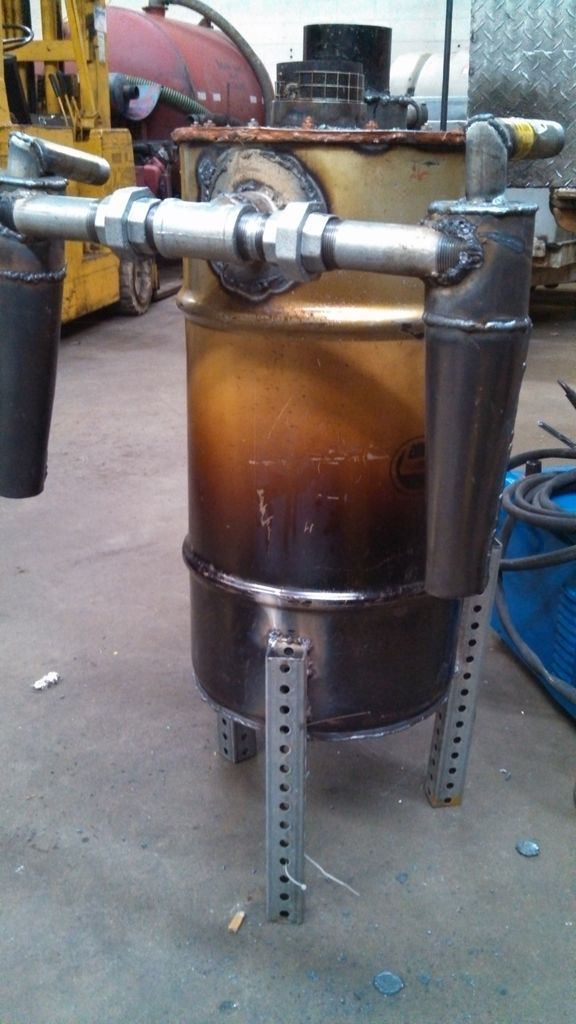

Now for some more potentially embarrassing pictures of my gasifier. The first picture is with the radiators mounted on to the unit. I split the gas in two from the output of the reactor to cyclones and then into two 1" copper pipes. The 1" pipe then divides the gas into three 1/2" pipes and drops to the bottom 1" pipe. The gas splits up again into three 1/2" pipes to ascend to another 1" tube and ties into the radiator from the other side. I incorporated a P-trap tying the two bottom 1" pipes with an 8" depth. My theory is the water will drain out as the machine runs while keeping a seal by not allowing air to creep in. I tested it with a blower and the system seemed to work. I was able to draw the flame into the warm air intake.
Yeah, it’s an ugly machine, but if I have dry gas, it will be worth it. I’m sure in a few years I will look back at these pictures and wonder what was I thinking?
Tomorrow I will implement Steve U’s suggestions to my hearth. After reading a bit of WK’s book, I pretty certain Steve U’s suggestions will solve most of my problems.
Bill S.


Hi Bill,
Well if you’re a little confused by the flood of info, don’t feel lonely. My picture is similar to Arvid’s, I just put my numbers to it. My latest build is an imbert design pretty much to the numbers for what I had on hand. The first pic is the imbert nozzle and hearth diameters design numbers listed in order from least gas production to largest gas production based on HP needs. Yes, of course there are other parameters, gasoline to woodgas power energy equivalents, wood type, humidity and who knows what else. Take little bites of some of this stuff, Nobody gets it all the first, second, third time, etc.
I started with my anticipated 20 HP engine size added 35% to the max gas production column and ended up on line C of the chart.
The second picture is my plan using a 100 lb propane tank for the shell. On the upper left of my picture are the actual imbert numbers on the left and “my” numbers (stuff I had close enough) on the right.
I have these all labeled so you can get a better sense of where the heck the numbers fit into the gasifier. My hour glass hearth just puts a cone on top of what is shown on the chart. Some people just use a tube here bolted to a flange.
I recently added an inlet air preheat shroud to my cyclone and increased the restriction opening to 4.75" ( line D) anticipating running a larger HP engine (25 to 30 HP). Speaking of cyclones I’m not sure that sending the moist gas to the bottom of the cyclone is a good idea. It’s going to have to come back up against the flow. A lot of energy used to change flow direction and moisture could possibly drop out here and make muck of the char. The gas will spiral at the top anyway if it comes in on the tangent and get sucked out the top while the solids (soot, etc) will slow down and fall to the bottom of the cyclone to a removable collection container. This char should be dry and powdery. My first cyclone fed down to within an inch of the bottom and the solids stayed in the gas stream and hardly any collected. I cut it back to just an inch below the botom of the inlet, later resized it the numbers, kinda, and it works like a charm, lots of char collected and a cleaner burn.
Go to My first small engine run in this forum for some pics of my build and changes. I also have a few vids posted of my runs that might interest you, they’re posted there. My latest gas was very good quality almost colorless.and ran an 8 HP Tecumseh for demo.
Hope this helps. I don’t have a lot of run time, but every change I’ve made has improved my gasifier and gas quality.
I also used Pic 3 to resize my cyclone, not exactly but far better than before. I couldn’t change the diam and didn’t change the cone length. I’m sure some just use straight sides with success, I can’t attest to it, not having tried it.
Pic 3 was a bitmap, I’ll change it and repost it.
Hope this helps, Pepe


1 Like
Thanks for this encouragement to Bill, Mr Pepe and looking over his system to date.
I’m afraid Bill to say much more until you get some engine run time on your system changes.
MY MISTAKE the last couple of years is saying too much, too soon and just let a fellow learn better step by step on his own, at his own pace. Alway hard to balance the over-helping from the too-shy watching standing aside and then seeing a fellow get disgusted, give up and walk away.
Regards
Steve Unruh
Oh. PS reread editng: IF your “J” trap condensate drain was meant to be liquid immersed?? Yep this work ok . . . untill you first engine backfire pressure puff liquid spray in the face. Or . . . system partial clog; minor cough; then Big pressure wave make up GULP sucks in ALL of your collected condensates right up to the engine. Ha! No actual harm - no foul done - just will air gulp in then killing the engine. We usually let most fellows figure these out on colored water pressure manomter tubes. But, by all means go ahead and try it. Personal experence is aways the best teacher.
Pepe,
Thanks for your input. I appreciate any information people are willing to offer. I may not always understand it the first time I read it, but it eventually clicks. I clicked on the above pictures but came up too blurry. I will try and find the pictures you said you posted before. I understand most concepts of the fixtures of a wood gas system. What I am unsure of is, it seems logical to me that an engine has a certain amount of cfm of fuel and air that is needed to operate. How does that volumne of combined air and fuel translate to the dimensions of the gasifier, fixtures and piping to the engine. I was able to get my 13hp engine to run on wood gas the second pull on my first and second attempt. I got lucky, I know but it brought a flood of encouragement to me. Now I want to figure it out so I know what changes are needed to fine tune or even start another build. I know there are mistakes I need to make on my own but I also don’t think I need to reinvent the wheel. Thank you for your input Pepe. I also watched your videos. i will post my questions there.
Steve,
You know appreciate and respect your input and suggestions. I just finished adjusting the hearth per your suggestions. Tomorrow I will fire it up. I see what you’re saying with the J-trap. The exact reason I went with this style is because of the potential amount of water that can come with longer run times. But yeah, the amount of water in the trap won’t be enough for a hiccup from the machine. I will try it this way first only because I’m anxious to get the motor running again. I may later install a 3 or 4" trap and see how that goes. So am I understanding you correctly the the water separates only when the gas is going up? If that’s the case I can make a few adjustments to make this twice as effective. I am excited for tomorrow for the run(if I have time). I do my work on this at work and a lot of times, work gets in the way. I didn’t have time to install a 8" grate below the fire tube. But I also don’t have room with my current set up. One thing still puzzles me. If the grate is suspended below the reduction zone, isn’t the possibility of losing valuable char exist?
Here are some pics of my hearth. I will post a video of my run.
Thanks for the info Pepe and Steve
Bill Schiller


.
Had a run yesterday and today with the gasifier and 13hp engine. It was a bitter sweet run. I was hoping for longer than a 15 minute run time on 16" of wood chips and 6" of char. The good thing is within 2 minutes I was able to start and run the engine. It was making good gas right away. The engine started on the first pull. It’s not too bad considering I only heard about gasifiying about 3 months ago.
The bad part is I knew I was using very moist hardwood chips. So as expected my run time was shortened. This in itself was a good learning experience. As Steve U said, the moisture will quench the burn area. It did show me how the unit reacts under such conditions.The other bad thing I discovered was the union fittings were loose. I installed union fittings all over this unit so I can easily dismantle it and take up a little piece of real estate when transporting it.
So what I did last night was cooked the moisture out of the chips on top of my wood stove in the garage. I wanted to see if my burn time would be any longer. So I got everything going this morning. I ended up with about the same burn time. So with the rest of my dry chips I will take Dave Bloom’s suggestion and run at 1/2 throttle and see how long it runs. I now know the reason for this test. Things are starting to make sense to me now. Prior to this I’ve been shooting in the dark. Another test I need to do is seal off all the openings after I light it and pressure it with air to check for leaks.
Here is a video of the run.

Can anyone tell me this? Why is it during my run, I had to shut the air intake completely off at the engine to keep it going? Is it because my char depth is too shallow?
Bill Schiller

Bill, Having to close off the air at the intake is a sign of air in your gas. Air leak some where.