Just curious David, where did you get your Coanda filters from? I bought one for my system from Bob Weir in Colorado. It really works well and has reduced maintenance to 1% of what is was previously. 
10 Likes
Hello Martin,
I got them from Powerspout; if I recall correctly, they come from New Zealand—they’re the turbine manufacturer. And indeed, the Coanda screens are easy to maintain.
Still, one day I’d like to add an automatic cleaner on top of them.
10 Likes
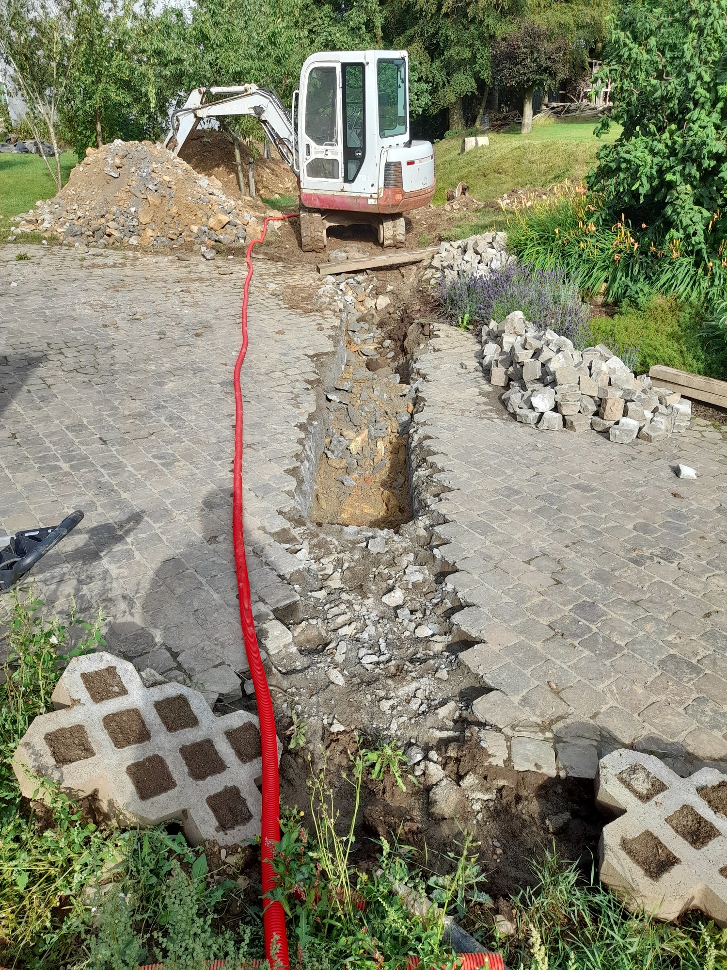
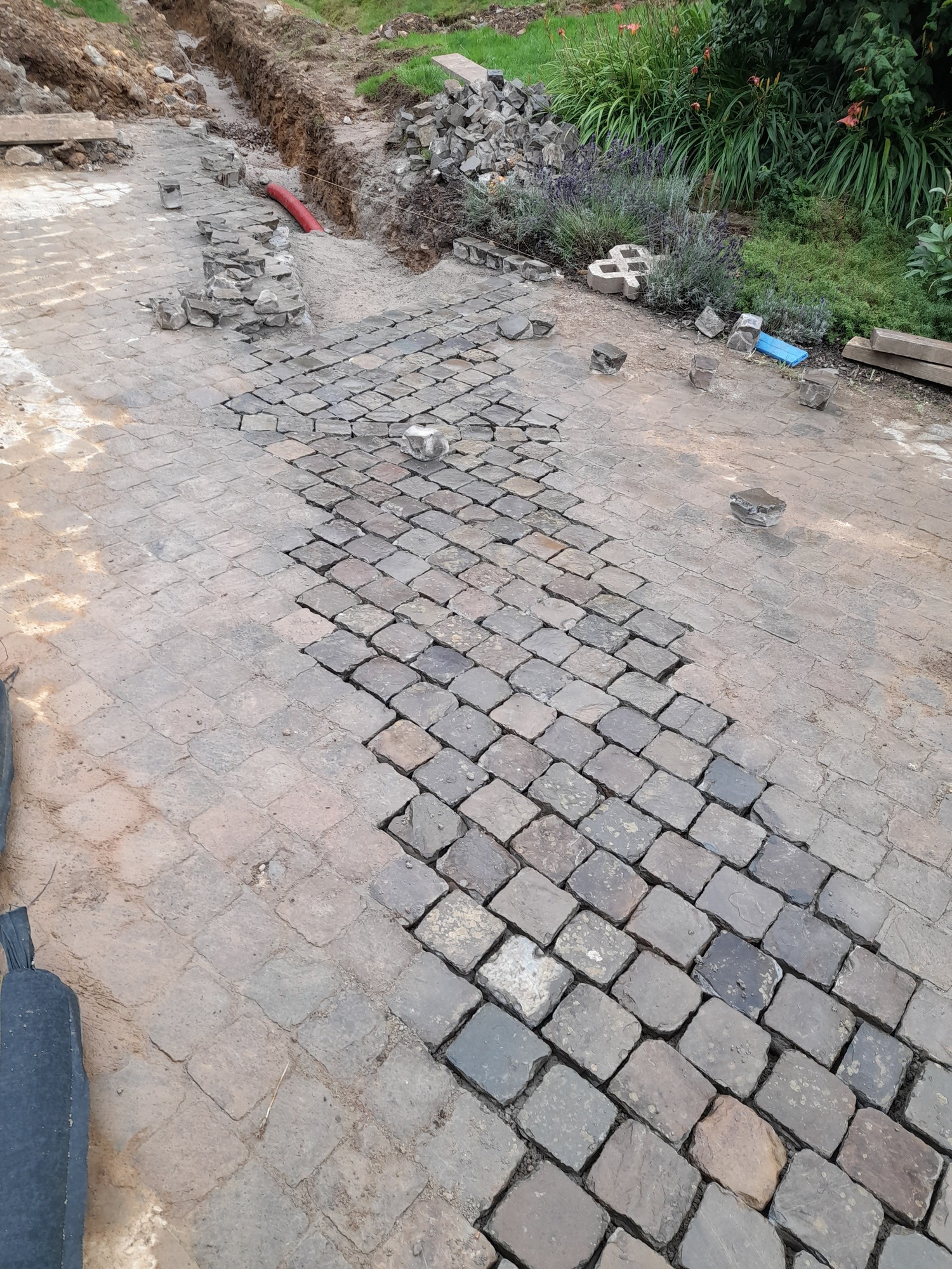
You also reminded me that I hadn’t posted anything else; here are a few photos of the installed pipes:
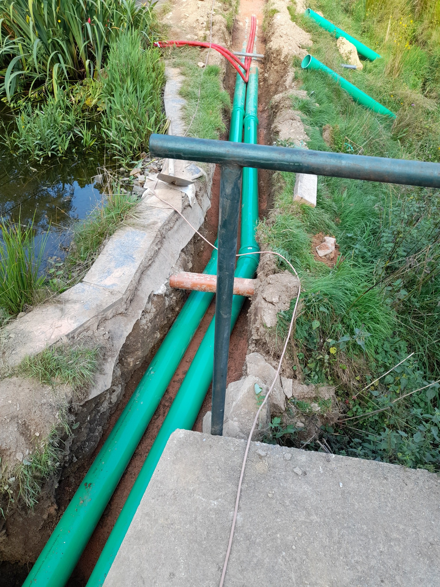
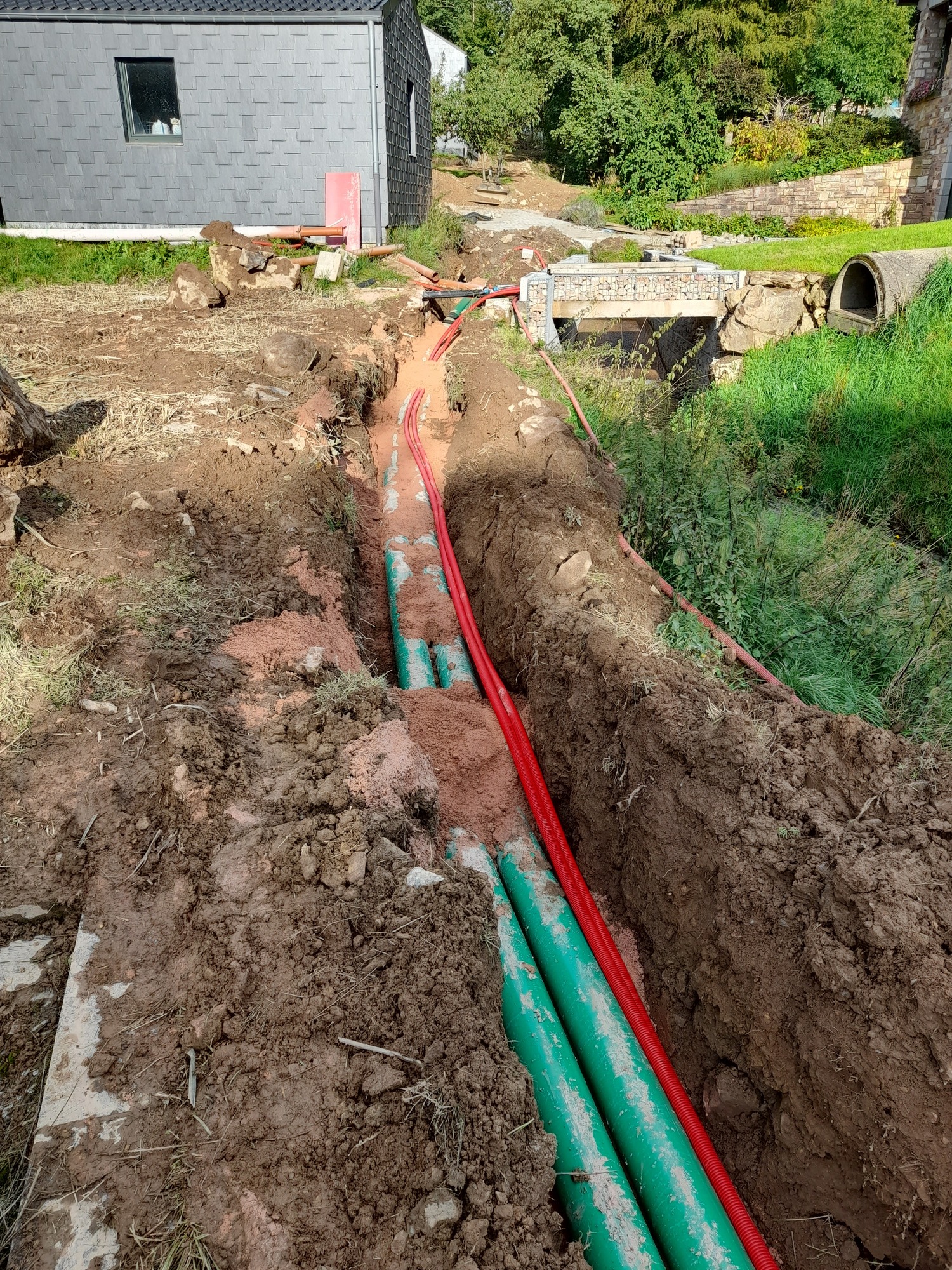
They are German-made pipes, and the seals are tested to withstand 6 bars of pressure; since I have less than 1 bar, I have plenty of margin. The run is about 220 meters long, consisting of two pipes with a 160mm outer diameter; the wall thickness is 6mm, if I recall correctly.
I also installed two 45mm conduits for the electrical wiring.
14 Likes
Here is the connection to the upstream chamber (Coanda):
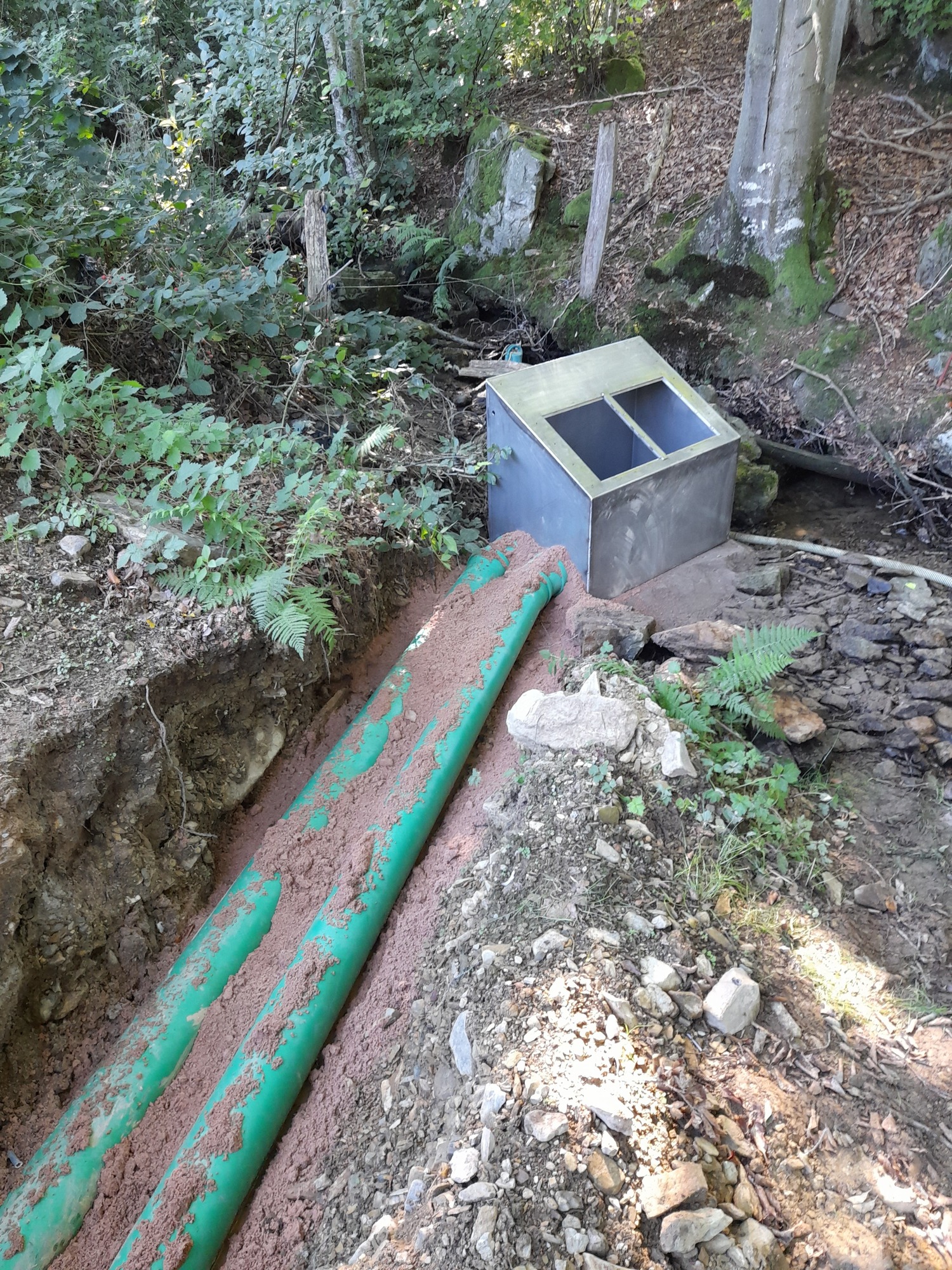
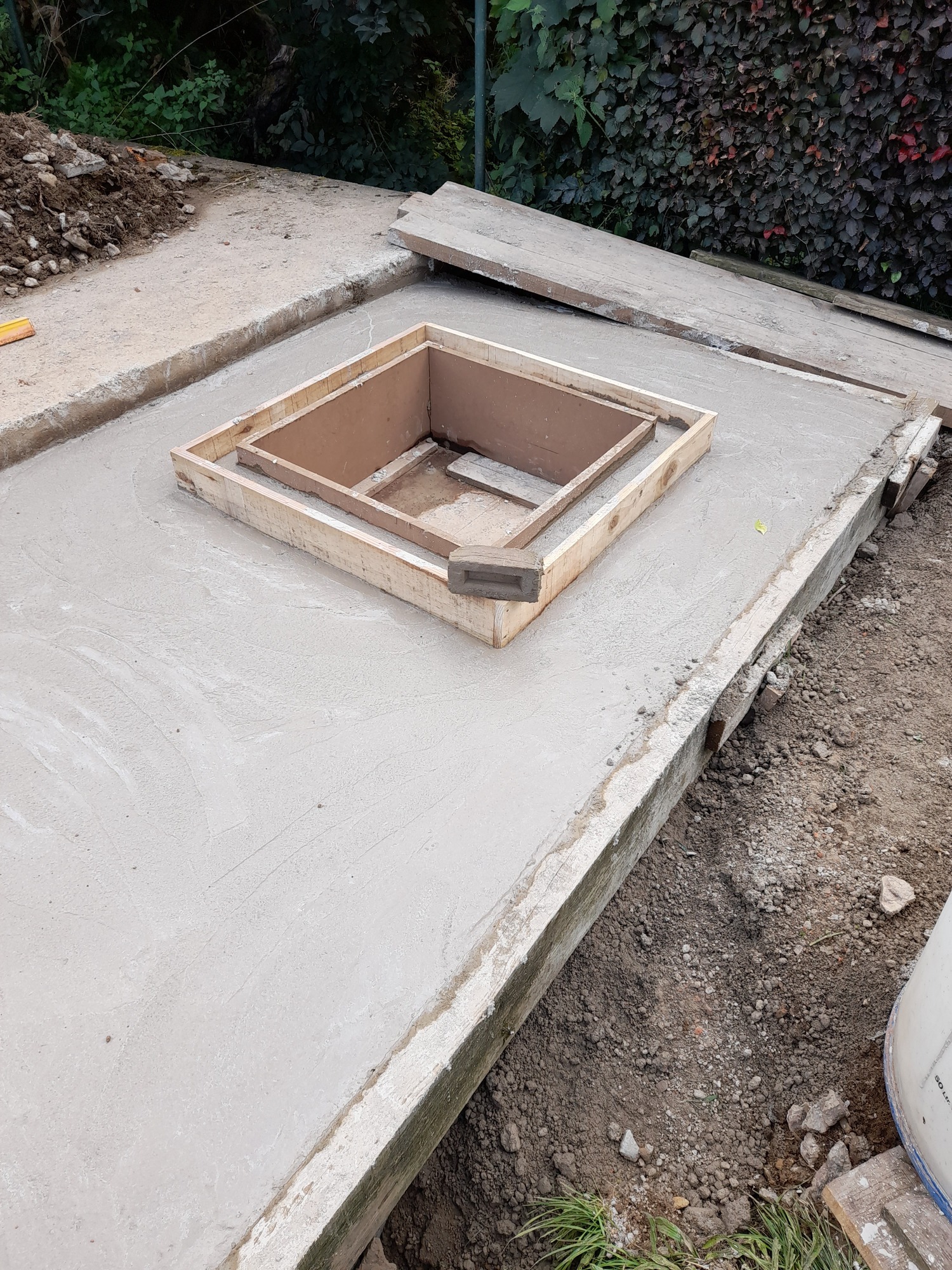
And the connection to the buried downstream chamber:
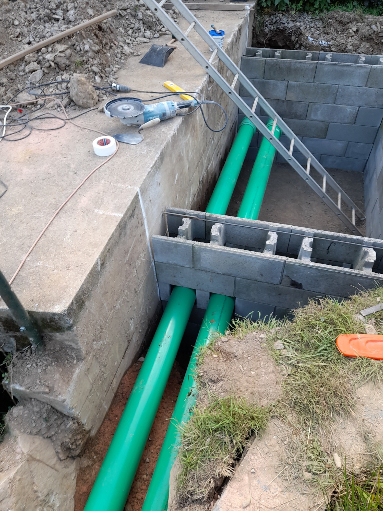
It is constructed using formwork blocks and is fully reinforced, as machinery drives over it.
19 Likes
Just a quick point of clarification: the pipe is laid so that it always slopes downwards.
If there were a low point, a vent pipe would be needed to let air escape; however, with a consistent slope, the air vents naturally at the upstream end, so no vent pipe is required.
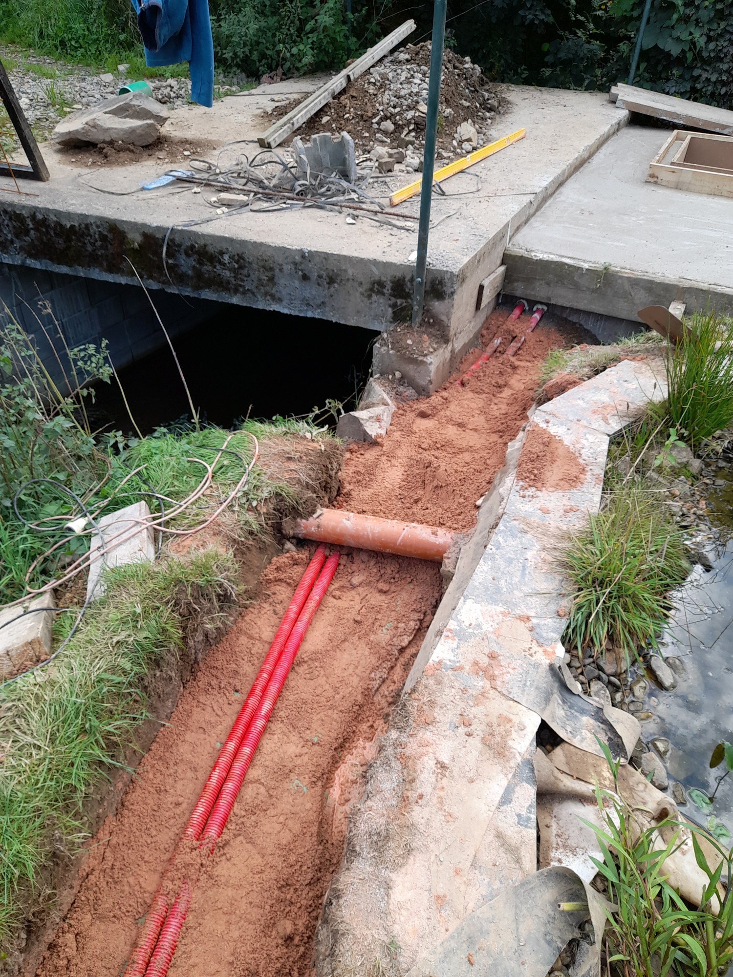
As you can see, I have securely stabilized the pipes using sand.
13 Likes

Here are the two pico-turbines, installed in the underground chamber and tapped into the two pipes:
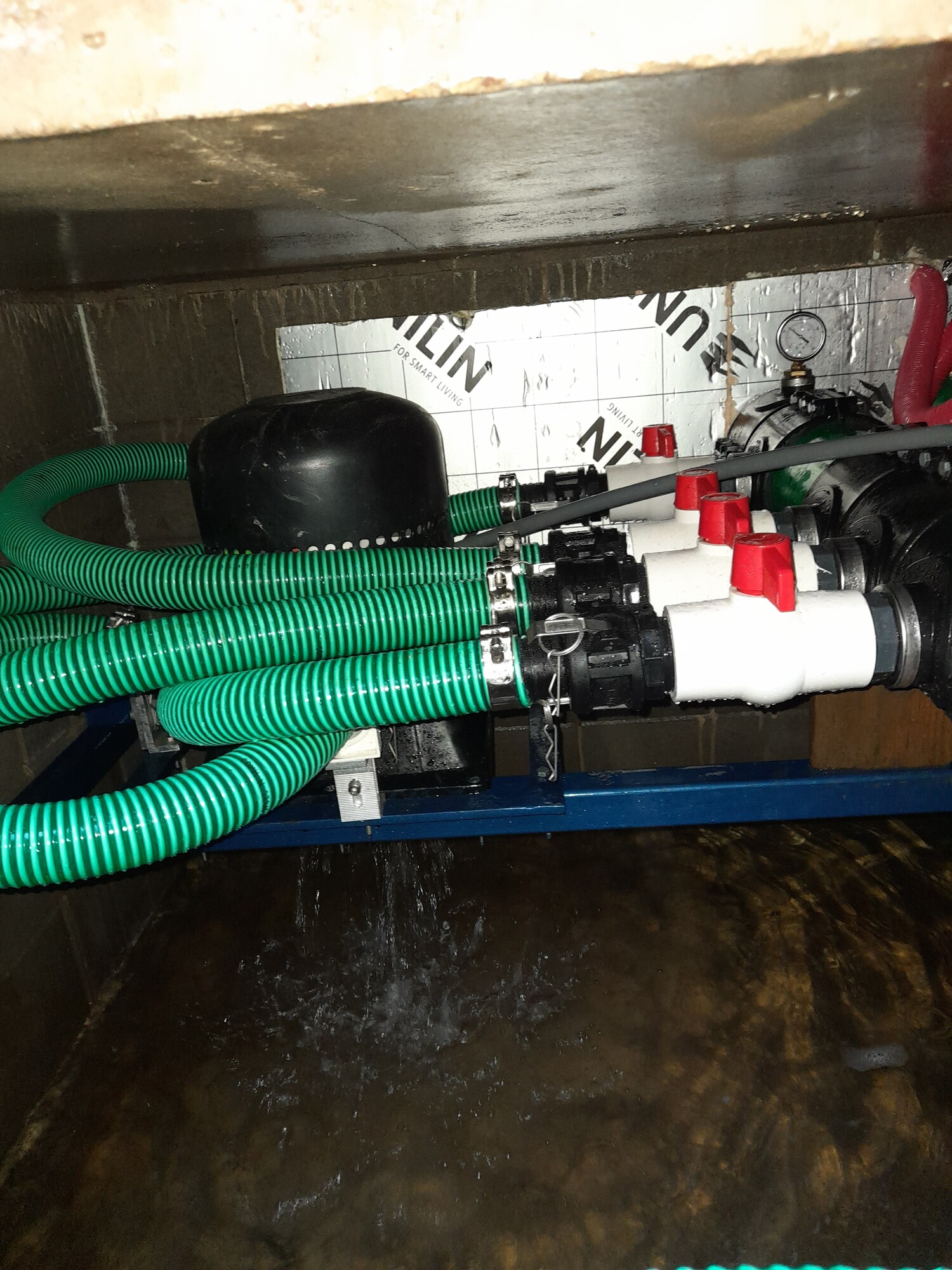
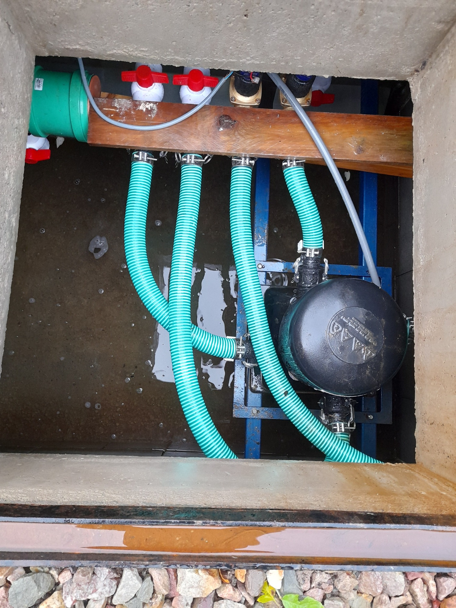
Water drains out at the bottom through an opening beneath a small bridge.
A stainless steel trap-style barrier prevents cold air from entering and noise from escaping.
I realize I don’t have a photo; I’ll take one at some point.
I am currently improving production using 3D printing and will show the progress later on.
15 Likes
And where are your turbines, David. This downstream chamber does not make a clear picture for the machinery.
Haha, I was so hasty and pictures were already on the way.
9 Likes
Oh darn, I didn’t leave enough suspense. 
6 Likes
These mini Turgos look pretty nice. I visited the site you referenced and the price starts bellow 50 ths CZK. It’s a retail price of 10 000 kWh, what is cca yearly maximum production of the turbine. Nice
6 Likes
One more question about design. Why two pipes? With the head of 6 meters and inner diameter 150 mm, single pipe flow is up to 170 l/s. This is far beyond capacity of both turbines and most probably beyond stream flow.
6 Likes
That’s a good question; occasionally, the stream’s flow rate exceeds the capacity of the two turbines, so I had originally planned to install a third one someday.
However, that happens so rarely that I abandoned the idea—it’s already uncommon for both turbines to be running at full capacity.
I had calculated that a single 200mm pipe would suffice, but the necessary fittings were hard to find, and a meter of 200mm pipe actually cost more than two meters of 160mm pipe.
So, I played it safe, especially since the labor involved in laying two pipes versus just one was virtually the same.
In fact, I think that if I were to do the job again with what I know now, I would still install the same pipes.
I would also like to add that the site features a calculator that appears quite accurate and takes all variables into account, including pipe friction.
13 Likes
Hello,
Following Martin’s questions, I am revisiting the topic of my pico-turbines.
This will make it easier for interested people to find the information.
I will now move on to the electrical and electronic aspects.
8 Likes
To begin with, here is what is inside the turbine:
-
the stator and permanent magnet rotor
-
the rectifier and the capacitor
-
the filter
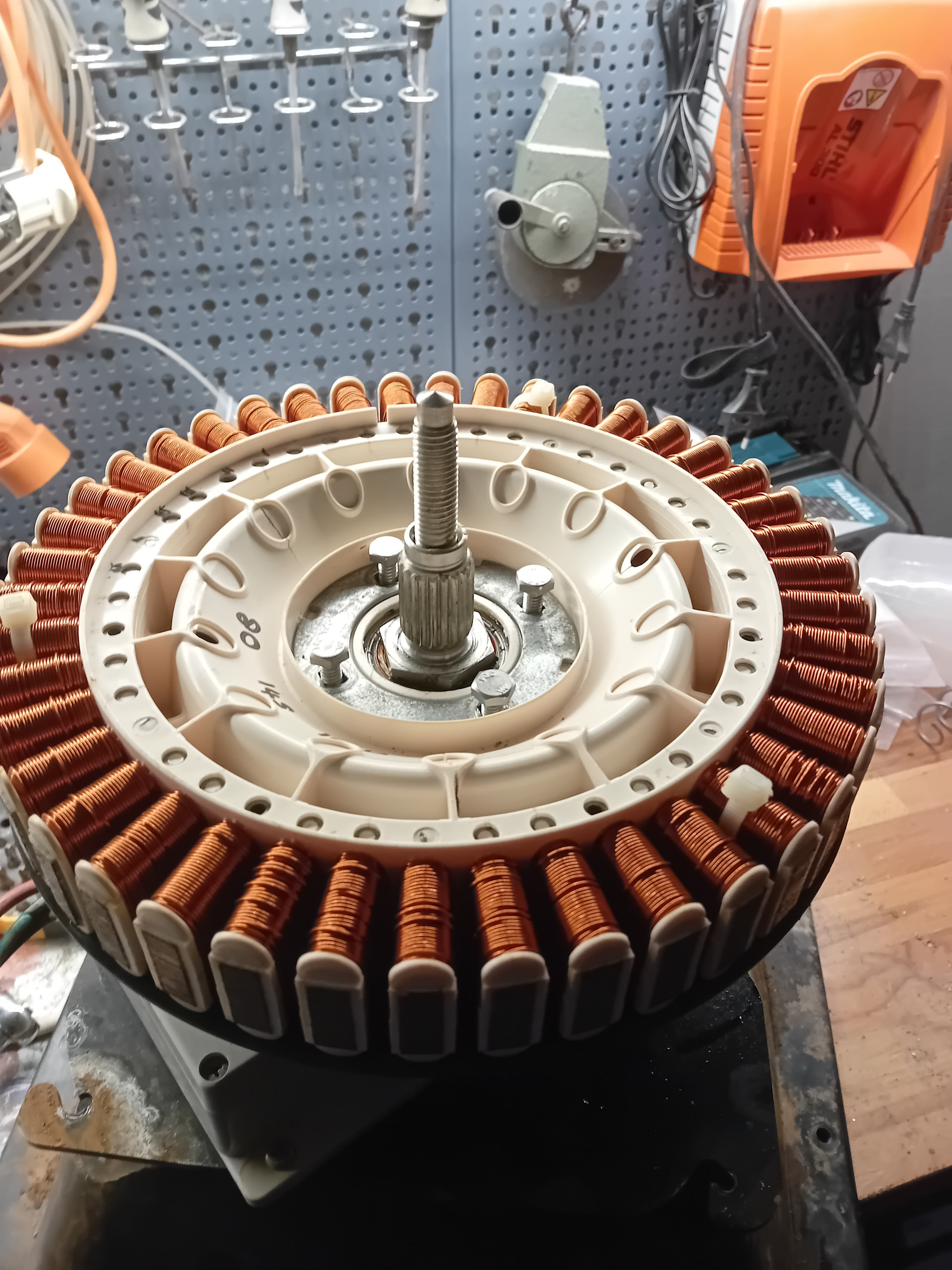
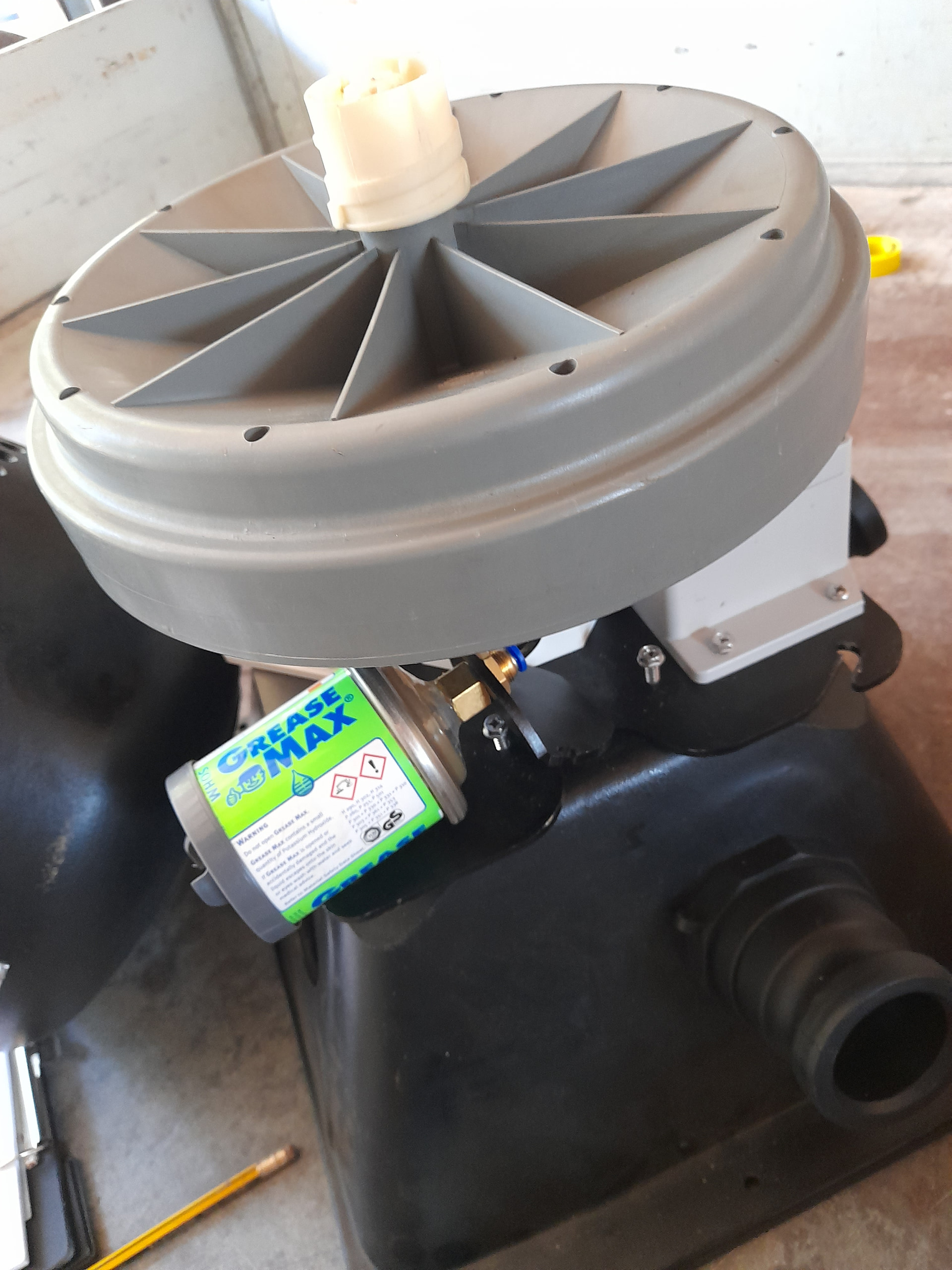
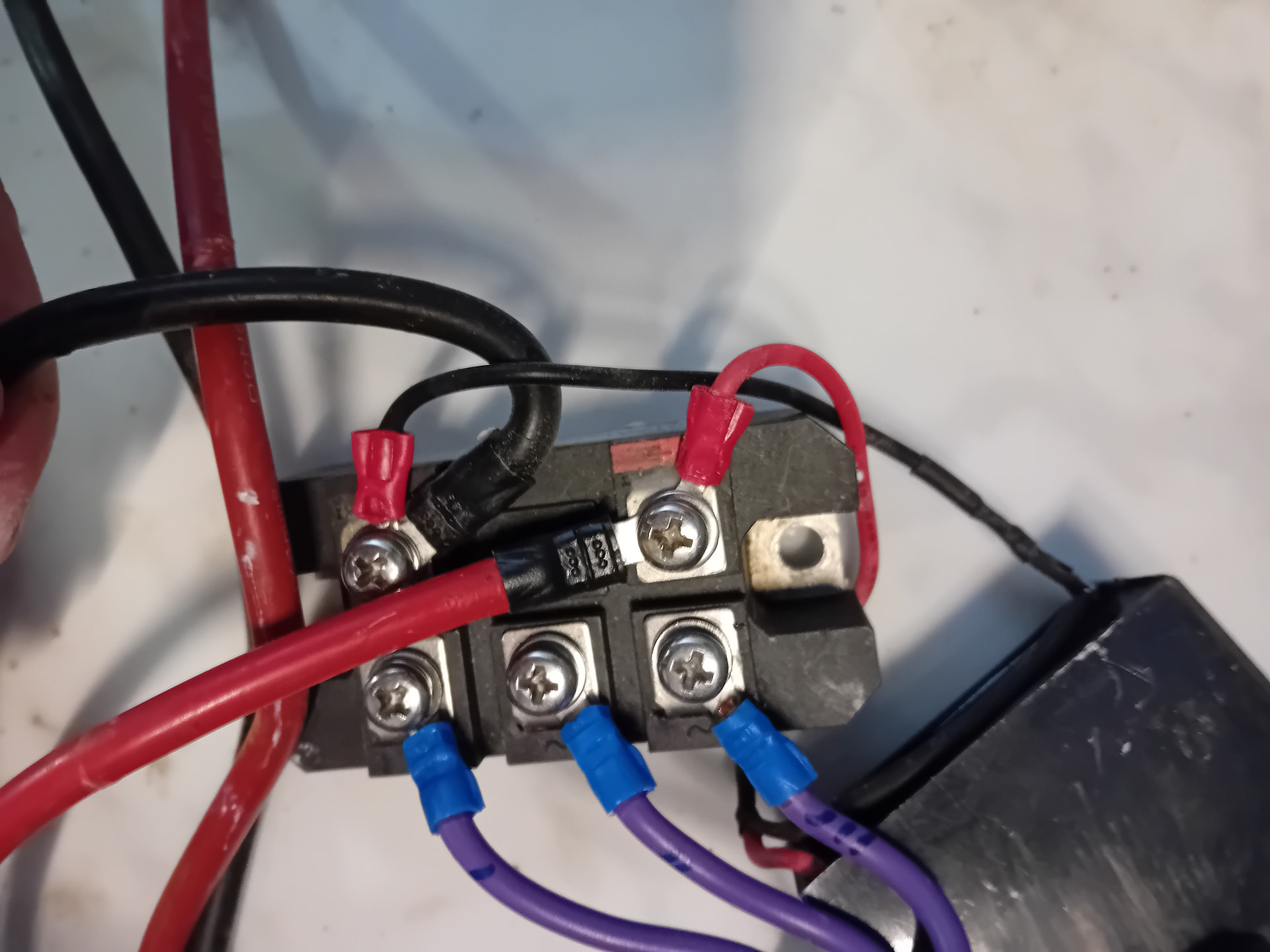
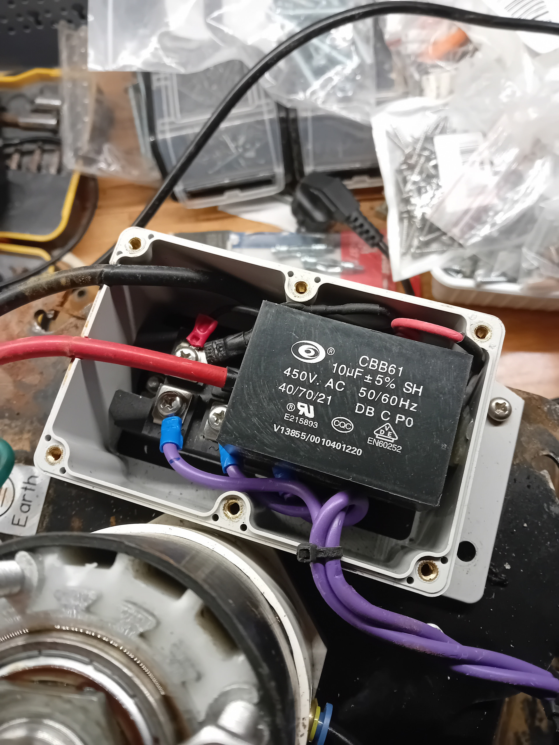
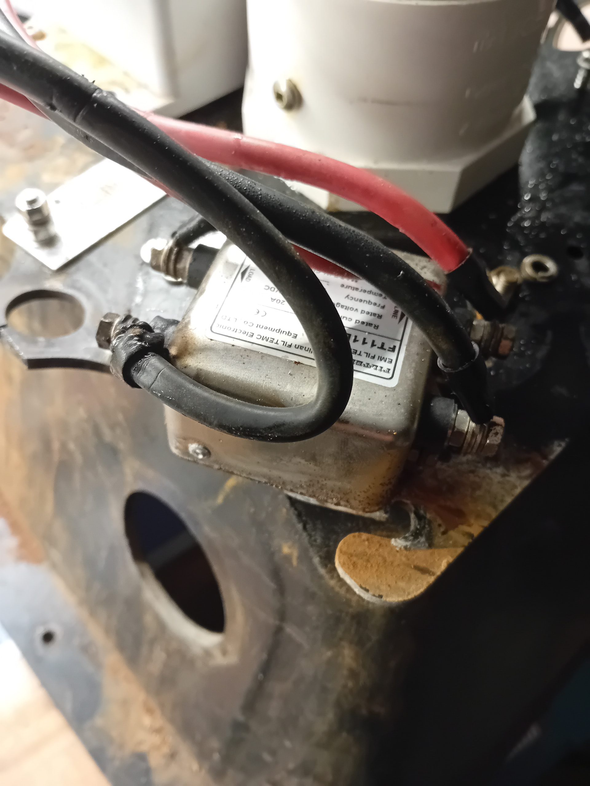
There is also a ground wire connected to the metal housing.
12 Likes
I’m beginning to understand your setup now. Very nice. It looks like you have Turgo turbines driving low speed alternators. I’m still unclear as to what voltage you are outputting from the turbines and inputting into the inverter.
I went to the Deye site and they have a lot of inverters! Which model number do you have? There is a distributor in Chile, but they don’t have many to choose from and they don’t mention wind or hydro inputs.
Does your inverter have a specifically designated port for a wind powered input? It seems strange that they would not then also provide for a dump load, as that power has to go somewhere or else the turbine could over spin. However, I like the Arduino solution. I can see how you can monitor the voltage rise to trip the dump resistor, but I wonder how it senses when to cutout the resistor when the inverter calls for power again. Maybe an under voltage condition?
In any case it is very instructive to me to see your installation, it gives me ideas of options.
4 Likes
Hello Martin,
Thanks for all these questions; they are specific enough to answer easily.
In my case, the voltage is the one selected on the inverter during the wind turbine setup.
You can create a sort of curve to ensure the turbine operates at peak output.
However, it also works with MPPT.
I won’t speak too definitively on that, though, as I don’t know if all permanent magnet alternators behave the same way, perhaps Tone or someone else has the answer?
As for choosing an inverter, the one I use might not necessarily work for you.
The first question to ask yourself is: what is my home’s current setup, single-phase or three-phase?
What power output do I need for daily use: 8kW, 10kW, or 12kW?
How many PV inputs do you need? I recommend at least two with independent management (which is common).
You should choose an inverter that handles batteries, a generator, and a backup system (so you can go completely off-grid).
The inputs are programmable for wind power, but let me reassure you right away: water power poses no problem at all, quite the opposite, in fact, since water flow is more consistent than the wind.
Regarding the diversion function: it operates such that when the inverter is active, it handles the voltage.
The voltage set by the inverter must be lower than the diversion setpoint; otherwise, the power will be diverted before reaching the inverter.
Inside the inverter, the inverter’s own resistor acts as the dump load; this also helps prevent the batteries, and the photovoltaic panels, from overheating.
As for the diverter unit itself, it only activates during the inverter’s startup or shutdown phases.
I believe that if the batteries are fully charged, it is actually the inverter’s resistor that dissipates the heat, though this would need to be verified.
Care must also be taken not to release the water flow all at once, as the turbine could otherwise wreak havoc on the electronics.
The diverter only handles excess voltage, but the turbine’s operating speed will be much less steady, as it will fluctuate between states of excess voltage, active consumption, and low voltage.
9 Likes
Thanks David for the explanation. I have a few more questions if you don’t mind.
I know I will choose a different inverter from yours, I have much lower power needs. But I was interested in checking out the specifications of an inverter I know can handle a turbine input. I haven’t gone into an exhaustive study of Deye inverters, but none jump out as claiming to have this ability.
When you say the voltage can be selected on the inverter, there must be a range, yes? Do you know what the upper bound is to this range? Also, what voltage is the turbine putting out?
If the inverter can handle a 230V input (probably a bit more when rectified to DC), it would make life much easier for me. Otherwise I have to jump through hoops. I like a 3 phase output from the generator as it can be rectified into a smoother DC than single phase. There are off the shelf 3 phase wind charge controllers, but all I’ve seen require a low voltage comparable to the battery being charged. Getting that voltage lower would require a 3 phase transformer to lower it, or 3 single phases. I have yet to find transformer that can get 230V down to 24V.
As Tone suggested, a work around would be a single phase motor supplying 230V that could then run a heavy duty battery charger. This is an added piece of equipment and not inexpensive if you want an intelligent one. This route would also require a custom diverter like your Arduino. But this seems to be the easiest route if the inverter cannot handle 230V (the other route being the construction of a custom transformer).
One final observation, are you sure there is an internal dump resistor inside the inverter? 640W is a lot of power to dissipate and you would not want that internal to the inverter. Solar panels can be shut off easily, they would just sit there no problem unlike a wind or water generator that would speed up with out load. Or are there leads to an external resistor?
Thanks again for all the help.
8 Likes
Martin,
You are certainly not bothering me; I am very happy to answer your questions.
I am not sure if all Deye inverters can handle wind turbines, though most likely the majority can; the software isn’t installed by default, but you simply need to ask the supplier to set it up.
I can check with a friend who sells inverters and performs the updates himself.
Regarding programming, a picture is worth a thousand words; you will find my current configuration for my turbines below.
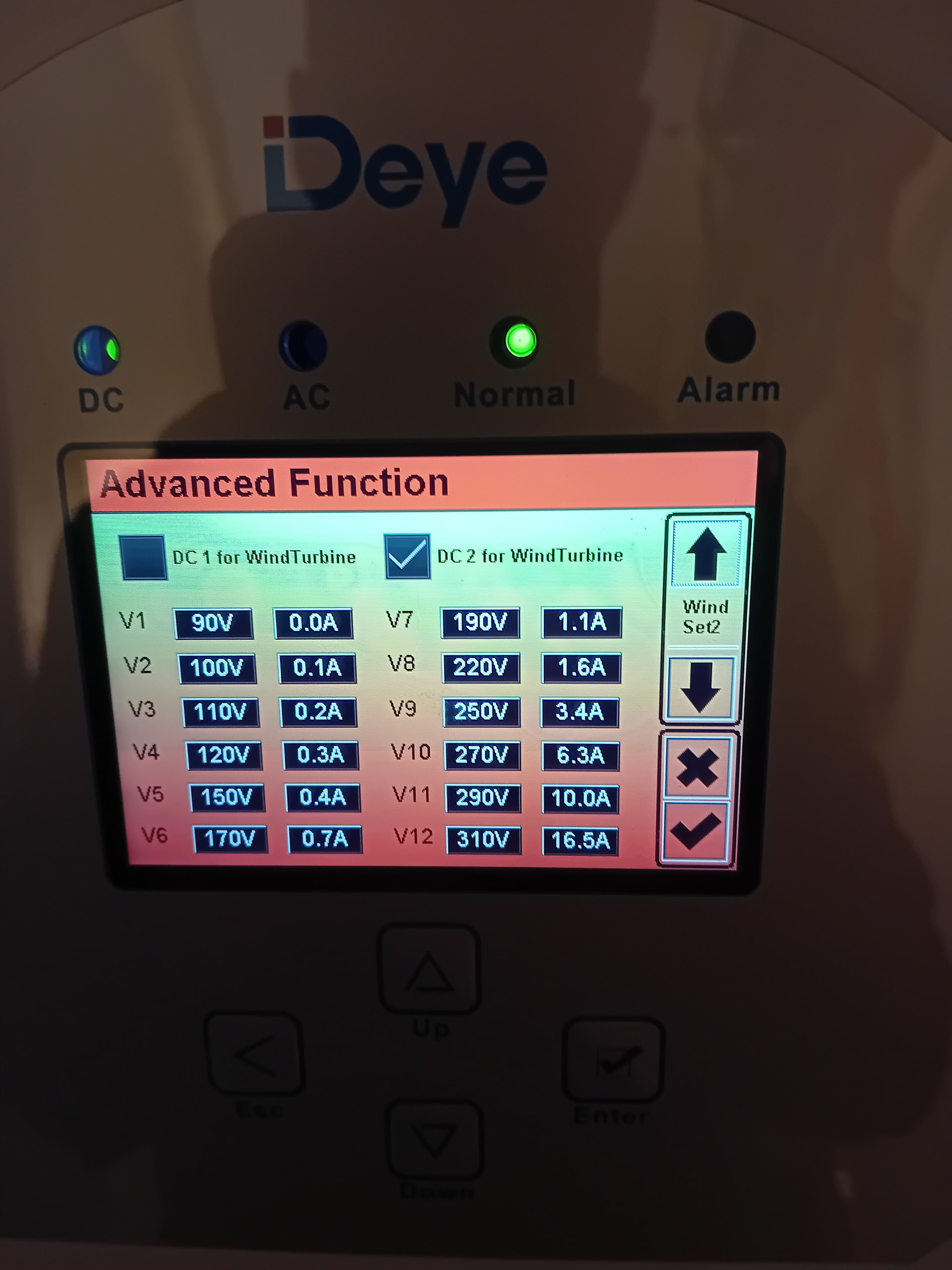
I tried to optimize the settings based on the valve openings, I can open 4 valves per turbine, making it 8 in total.
The ranges are 50V to 480V for voltage and 0A to 20A for amperage. So, the answer is yes: 230V works perfectly, that is the voltage I use.
I just consulted an AI about your alternator, and here is what it said: If your turbine is designed to run at 24V, you cannot simply switch it to 200V using the inverter; it would spin too fast and burn out, because voltage regulation affects speed (for instance, my own turbine is designed for 230V).
However, if your turbine is designed to run at higher speeds but is currently operating at a reduced voltage, that wouldn’t be dangerous for it; so, you would need to know the turbine’s rated RPM and voltage.
Regarding diverting excess power to the inverter’s resistor: if there is a load (power consumption), there won’t be any problem, and the rotation speed will remain stable.
However, if there is no load, the turbine could spin out of control and break, especially if you have a steep slope.
That is where a diversion controller becomes useful; naturally, this controller would divert power to a resistor located outside the inverter.
A simple example would be the inverter entering safety mode because of a sudden, excessive power draw; if that happens and there is no diversion system in place, your turbine risks breaking.
Feel free to let me know if you don’t quite understand, because it’s not simple to grasp, and the translation sometimes adds further complications.
7 Likes
Ok David, I’m beginning to understand.
I didn’t understand you had custom software, or even it that was possible with a Deye inverter. Very impressive.
So the screenshot shows voltage and amperage. Is that the turbine power curve? I don’t quite understand how those numbers are derived.
I thought I would show you what I am working with:
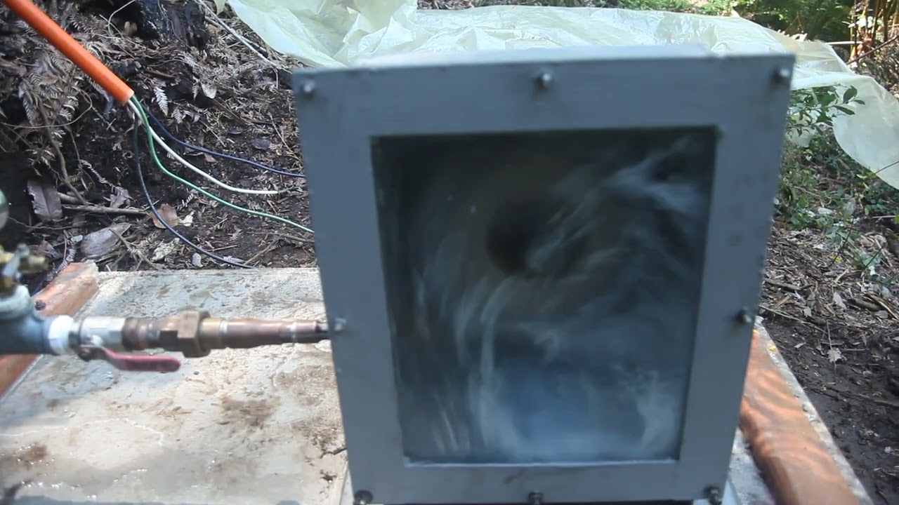
This is a video of the turbine unloaded. The alternator is a PMG made for vehicles so even unloaded, I am driving it at a safe speed. I built the turbine wheel myself with cast spoons. When I balanced it, I spun it at 3 times its loaded design speed, so I am pretty certain it is robust enough. Even so, I would add a diverter just to keep wear and tear down, especially on the bearings.
Ultimately, I have to up the voltage for transmission. I could do it with a transformer, but since the alternator is only single phase, I would swap it out with a 3 phase motor to get the higher voltage and a smoother DC when rectified. I needed a pulley system to get the current alternator up to speed, but I would try and mount the turbine wheel on the shaft of a 4 pole induction motor. This motor is perfectly matched to the most efficient turbine speed and would remove inefficiencies introduced by the pulleys.
I think your installation regarding going from 3 phase AC to DC and then into the inverter is the best solution. To drop the voltage so I can put it through a dedicated wind controller requires a fair amount of cost beyond the cost of the inverter. I had considered going through the solar input of an inverter, but dropped that idea because I read this could destroy the inverter. But I think your conditioning of the power with a capacitor and a filter solves this issue.
I’ll have to look into the programming software for Deye inverters.
Thanks again!
8 Likes
Hello Martin,
I’m glad my explanations helped clarify things for you.
Regarding your question about the curve: I had to tinker a bit, opening the valves one by one, to find the settings that yielded the best output.
I started by checking the MPPT reading and then made small adjustments.
Of course, the curve will be different for your Pelton turbine.
I can’t watch your video; it’s set to private.
I consulted an AI, and it confirmed that a single-phase alternator is much less stable than a three-phase one and, as a PMG, is very rare.
It also indicated that a capacitor is essential to avoid damaging the equipment.
Switching to a three-phase system would be ideal, in my opinion.
What is your head height (vertical drop)? And do you have an idea of the water flow rate?
I analyzed which turbine would be best for my setup, which is why I looked into Pelton turbines too, but in my case, the head was far too low.
5 Likes