Martin, before you buy a Deye, make sure the wind option is there. I think we all have sg04, not sold anymore. Make sure sg05 has the same wind option.
7 Likes
Hello David,
This has been an enlightening conversation.
I will have to research how MPPT works. I know it adjusts voltages and amperage to get the best output, but just how it does that is a mystery to me.
On my installation, I have 65 meters of head and about 1.1 liters per second of flow. The runner has a pitch diameter of 18.5 cm. These parameters give a jet speed of 35 meters per second, and a runner speed of 1770 at its highest efficiency (1/2 of unloaded speed). As such, a 4 pole motor would be a perfect match at this speed, driven slightly over its 50hz speed as a motor.
The alternator I have presently is an automotive type permanent magnet one from China:
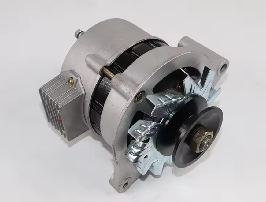
I took it apart to try and get 3 phase AC from it, but it had only two windings hooked together in parallel. I could get 24VAC from the alternator when I connected them in series, but that didn’t help much for my transmission issues. All together, this is a weird beast. Thankfully, it was cheap.
I have adjusted the video properties, hopefully you can access it now.
10 Likes
Thanks Joep, I will definitely look into that.
5 Likes
I can view the video now, thanks.
It looks like you’ve done a great job building the turbine. It’s far from amateur work; I bought mine as-is and am just trying to improve it.
As for the inverter, it’s the Sun-12K-SG04LP3-EU model. We’ll need to verify if the new models still have that feature, as Joep mentioned, but I assume the manufacturer would improve the model rather than remove features.
5 Likes
I just took a look at the user manuals for the SG04 and SG06 available on the DEYE website. Both show in the advanced options this page:
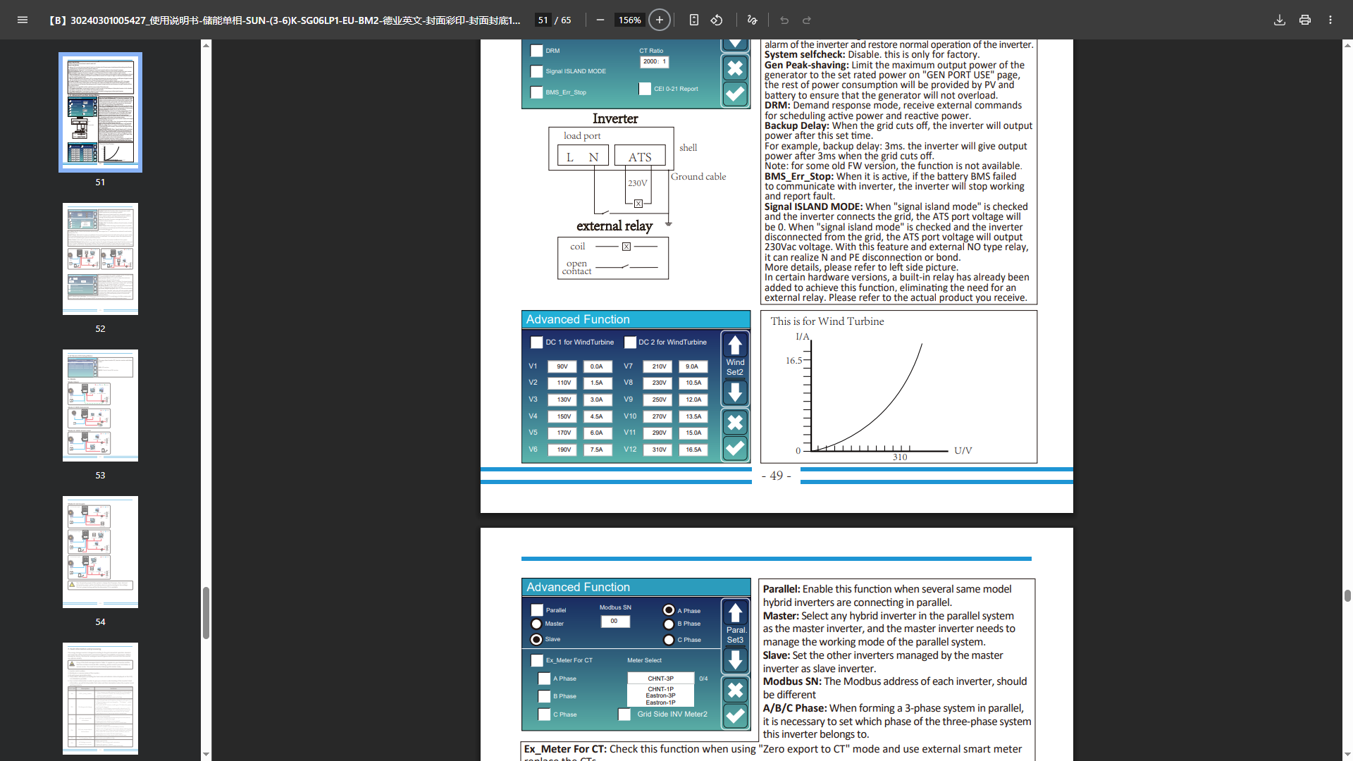
It shows the same table David that you posted earlier. However, there is no explanation about how to use it nor anything about where to connect the wires, etc. I will continue to search for this info…
6 Likes
As I recall (I can’t remember which thread this was on) Tone also input the rectified output of a 3-phase motor into an inverter. However, he ran his off an engine that is probably governed. I am not sure how my hydro driven motor would behave. It scares me because the rectified output of 230VAC is 325VDC, which is getting towards the top end of acceptable voltage for the inverter. It all comes down to how the motor/turbine voltage and amps vs rpm curve behaves. I am not smart enough to figure out then what happens when you feed this into an inverter and how the volt/amp table affects things. (I really hated the electrical engineering course I took. Imaginary numbers and all…)
I feel like a ship on an ocean getting rocked back and forth. One way to solve all this is to get a 230V single phase motor and a toroidal 230V to 24V transformer. Rectify the output and use an Arduino to control a relay to feed power to the batteries until 13.8 volts is reached. Then shunt the power to a resistor. Easy to do. I won’t get the absorption and float phases, but this is how cheap wind controllers work. I could even PWM the output to the batteries, but I’m not sure how to do that and keep the rpm’s under control. This is really starting to give me a headache. 
6 Likes
I can see why your head is spinning; you’re describing so many possibilities that I imagine you feel overwhelmed.
I’ll do my best to clarify things for you.
If you simply want to heat water with your turbine, you can just rectify the current and connect it to a heating element; you’ll just need to use a sufficiently powerful element to handle all the energy and provide a safety margin.
If your goal is to power home batteries, I recommend a Deye inverter; it will manage your setup without any major hassle. Regarding the screen I showed you in the documentation, specifically the advanced options, that model supports wind turbine settings.
I can assure you that mine goes up to 480V in the settings and can likely go even higher for MPPT purposes.
I don’t have easy access to my inverter’s label right now, but I’ll try to let you know the maximum value for the PV inputs tomorrow.
Connecting the turbine is very straightforward, it’s the same process as for solar panels: connect the positive (+) to the designated terminal and the negative (-) to the other after rectification.
Also, be sure to add a ground wire for safety; water and electricity don’t mix well, so caution is essential.
For your water intake, I have a very simple solution: a “normally closed” solenoid valve.
When you apply power to the valve, it opens; if the power cuts out, the valve closes automatically.
This valve solves two problems: it opens slowly, preventing voltage spikes at startup, and if the inverter goes into safety mode or a fuse blows, the water flow stops gradually, protecting your turbine from damage.
Don’t make the same mistake I did, and choose a ball valve with a servomotor.
8 Likes
Martin, your video showcases the work of an expert.
You mentioned that the alternator is single-phase and rewired for 24V; the power transmission setup indicates a rotational speed of 3000–4000 rpm. If it is a 4-pole generator, the AC frequency would be 100–130 Hz. A question for you: can you measure the voltage and frequency at 3000 rpm?
A 220V-to-24V transformer is the most common type available, so you can get one very cheaply—or even for free at a scrapyard. You could use it to step the voltage up to 220V AC, then rectify it to get approximately 310V DC, which is ideal for an inverter’s DC input. You don’t need to worry about damaging your equipment; you can connect this voltage to your inverter just as you would solar panels. It will certainly work, though you could achieve optimal results by enabling the “wind turbine” function, which allows you to match the input to your specific power source.
You mentioned the generator I drive with a diesel engine; that engine uses a centrifugal governor to maintain constant speed. It occurred to me that if you installed a centrifugal governor on your turbine—linked to a water valve that opens or closes—it could keep the speed within a narrow range regardless of the load… sticking to the principles of being cheap, simple, and DIY.
9 Likes
After a dive into induction generators, this is what I found. I always knew that if you tried to pull too much power from a capacitor excited induction motor, you could collapse it and it would stop generating electricity. What I didn’t know is that similarly, if you try to overdrive the generator it will also collapse. The voltage will not continue to rise like in a pmg generator.
This is heartening in that I don’t have to worry about extreme voltages if the generator speeds up too much. So I am back on board with sending power into the inverter.
What I have read, maybe this is with other generators, is that the MPPT in inverters can cause current spikes as it scans the input. These can damage the inverter. I am still learning, but this probably won’t happen with the voltage limitations of an induction machine.
So that’s the decision at this point, maybe  .
“I’m a man, but I can change, if I have to, I guess.”
9 Likes