Hi all! Brand new here and needing advice. Built an Imbert type Gasifier and have a single filter stuffed with stainless steel pot scrubbers.My flame is not as blue as i would like and upon holding a clean dry white rag over my flare stack after an hour run and after putting out flame, it had a black sooty covering that was dry and mostly blew off with compressed air.Going to add secondary filter and wanted thoughts on either a baghouse type or just hay or wood shavings.You can see my unit flaring on youtube(docdcox). Thanks and glad to be part of Driving on Wood. Dan
Hi Dan, About 34 minutes into this video is the latest flare we should look at? http://www.youtube.com/watch?v=NznGOoDGyCY&feature=plcp
Nice work. Lots of videos to go through!
I’ve pretty much used wood chips in our filter… always seemed to work ok.
and yup right around the 32 min mark… i’d try running an engine on that
I’m no flare expert but I think the yellow in your flame is just soot. I believe white indicates hydrogen. You’re pulling a lot of vacuum on the system, and soot is very hard to filter out. The napkin test is much more telling. If you’re not getting tar, I’d definitely try it on an engine. Soot won’t hurt anything, it burns in the cylinders.
Good morning Danny,
Thanks for posting and sharing the videos,
I’m with Arvid and Ray. At about 34 min the gas looks good.
Nice looking gasifier! You have some time and money in it.
I think with enough filters one might be able to eliminate the soot. I am using the gasifier on vehicles and have limited space so I keep the filters to a minimum. I use hay and it seems to work very well. Also I have seen no evidence that soot getting to the motor will harm it.
With a tar issue I don’t know of anyway to filter it. I think the only way to handle it is not to make any. The tar will damage a motor in a hurry.
After a new gasifier is “burn in” as I call it and a char base has been established there should be no smoke from the flare exit even at start up. Maybe just a light haze just enough to see.
Usually I can tell the quality of the gas from the performance of the motor. If I have any doubt, at shut down I will open a vent and look at the gas. If I am able to see more than just a light haze (which is very rare) I will start the motor and run on gasoline a couple of minutes.
Good Job
1 Like
Thanks Ray,Chris,Arvid and Keith for taking the time to look at my long winded video and offering your valued opinions.I really like this site and hope to contribute when i can.I appreciate you all making me feel welcome. I already know Arvid,he’s a good guy.Started on a extra condesate drain on bottom of my hopper and am adding one more filter.I built this large gasifier(first one)to run a large genny that i don’t have yet, so it may be a while before engine run.May have to build a smaller gasifier to run my small engines. Thanks…Dan
Hi Danny,
Very nice workmanship and a decent looking flare. After some mods, I’m finally getting some blue streaking in my flares. I still need to work on more gutters. Your video made me smile, I’m glad I’m not the only one that does the scratch my head, wonder what/// walk around. lol. I also would try to run an ICE with that gas.
I noticed at 6m in your video that there were sparks in the flare(I realize there was no filter yet). These are larger particulate matter that get through the cyclone and the final filters pick up(as I understand the process).
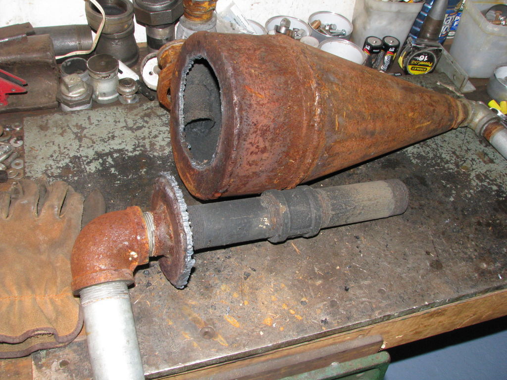
I’m not an expert for sure, so let me show you some of my observations. I’ve done tear downs after every major mod, just to see what’s happening inside.
Pic 1 Original cyclone 7 3/4"d, top part 5" long, cone 12" high. Major mistake on length of cyclone outlet tube. It was so close to the bottom it sucked up everything as soon as it fell down.
Pic 2 The bottom of the cyclone outlet should be approx an inch or so below the bottom of the cyclone inlet.
Pic 3 This is all the char(soot?) from the 1st run, Char is very fine. dry and silky to the touch.1 hr. run.
Pic 4 New cyclone same diam, top now 11", cone 12".
Pic 5 Cyclone encased to preheat incoming air and feed it to a single port air inlet manifold.
Pic 6 Metal char trap and char.
Pic 7 Char is very fine, dry and silky, but the amount deposited now is 20 to 25 times the previous cyclone dimensions.
Pic 8 Nozzle hole diameter is another consideration for best penetration to establish and maintain the hearth core fire. My initial holes were per the design calling for 1/2" d. This proved too much. SU suggested I start at 1/4" d and move up if needed. 1/4" seems to work with my other dimensions. Note my nozzles are drilled caps installed with 2000 degree anti seize for easy (lol) removal if needed to redrill.
Rest of photos on next message.

http://jamclasses.drbanjo.com/static/dimages/3.JPG
http://jamclasses.drbanjo.com/static/dimages/4.JPG
Hey Richard, Thanks for watching and commenting. Yeh, i’m not going to have any hair left if i don’t get this right soon.I can see where your pickup tube in your cyclone would be a problem as long as it use to be, mine are 1"-2" below the imput on both cyclones. Doing more mods this weekend and hopefully thats that. Dan
I noticed later in the video that you sped up the fan to try to increase the hearth temp. My next fan will be speed controlled. However, this lead me to consider nozzle hole diam and air penetration into the hearth on my own unit. Further it lead me to think my fan was under sized/powered which puts me presently building a larger fan, among other things…
Hope this helps, Pepe

http://jamclasses.drbanjo.com/static/dimages/5.JPG

http://jamclasses.drbanjo.com/static/dimages/6.JPG
Hi Danny,
I thought you might like to know, there is an answer! Maybe not right away and maybe not this one,but here’s a little trip I took. I don’t know how your unit is put together internally, but if you have bolted in a burner of any kind without a gasket, you may want to check for tar build up where plates meet. Gas leaking here cools enough to deposit tars at the joint It’s an unlikely place for tar and a clue there’s an 'internal" leak. The high heat in this area really stresses metal, thus a gasket to contain the leak.
When I saw your flare color I thought it looked remarkabky like my fluidyne flare. My flare’s velocity gradually decreased leaving me scratching my head. Shucks, I said, under my breath. It wasn’t until I did a complete system tear down that I found my answer. It was the last item that I unbolted from the unit. It was the fire tube and flange. I was checking for the gasket. Yup, I did remember to install it. Then a look at the fire tube to check the weld was when I saw I had only tack welded the tube to the flange.Now gas and steam could get sucked around the tube missing the reduction zone and condensing out where it was cool enough down stream. Well, I found a quart of water in the 1 1/4" line between the cooler and the filter, but no water under the grate in the filter. Filter material was well tarred up from this run. Check yours for tar. It’s another clue for low hearth temp. Aha, there’s where most of the steam from the “internal leak” ended up. This water in the line also restricted the gas flow lessening the velocity of air through the nozzles cooling the hearth temp. I also found tar build up around where the tube meets the flange. More fan doesn’t seem to be the complete answer, me thinks and thinks it to death. lol.
All of this brings me to, “did I pressure test my unit”? Yes and had a few minor rewelds, retest good, no “visible leaks” and a great learning moment for me unfolds. However, in the end I found I had an "internal " leak. The gas and steam goes around the unwelded tube and joins the rest of the stream to exit the outlet all together normally, thus the “internal” leak is undetectable in a pressure test. Plug up the outlet “internal” leak stops and if no other leaks, pressure stabilizes instantly.
Pic 1 Fiberglass gasket between mounting flange and fire tube flange.
Note size of nozzle hole 1/2"d. Later model becomes 1/4"d. The
grate now is a full tube diam with about a 1/2" space all around. Also
a much larger pile of glowing char to do the magic.
.
Pic 2 Here we see my error, the reason for water in the line and my “internal” leak.
Finally found something physical that absolutely adversely affects performance
Look closely and carefully where the flange meets the fire tube and you will see that it is only
spot welded in a few places. Look about 5 o’clock and 8 o’clock.I don’t know how I could have
missed that//
Link for my fluidyne flare color; http://youtu.be/OdQStkd-WWk
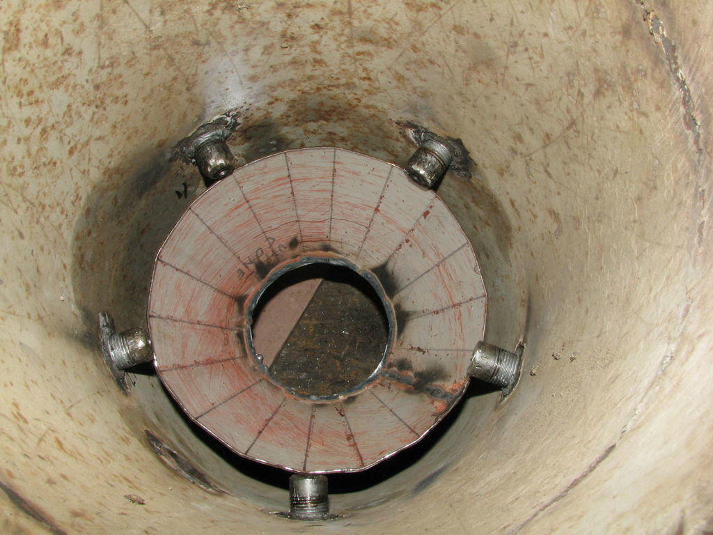
Pic 3 This is the hearth ready to install in my gek like unit.
Pic 4 The hearth is installed with a fiber glass gasket to prevent an “internal” leak.
Pic 5 Now all the gas “has” to take the only path and go through the restriction. Note the drilled
caps for nozzles, 1/4"d. Caps installed with 2000 degree anti seize. Just in case.
Pic 6 Burner insert ready to bolt onto the outer shell. This unit produces a good quality gas and I
ran a 5hp roto tiller and an 8hp B&S on it.
Fraser River, BC
Link for my Gek flare color; http://youtu.be/_JOD1BHEqS4
Less intense orange, more orangish/ bluish/whitish tinges. Runs my small HP ICEs well.
I hope helps shine a little light.
Pepe
http://jamclasses.drbanjo.com/static/dimages/1_1.JPG
http://jamclasses.drbanjo.com/static/dimages/2_1.JPG
http://jamclasses.drbanjo.com/static/dimages/4_0.JPG
Hey Richard; thanks for your imput, i’m sure of my welds as i triple checked as i went along. Two things i did notice is your distance between your nozzles in relation to your restriction size looks wider then mine. I have 1/4" holes in my nozzles and they are appx. 5" apart over a 3" restriction. Also i noticed your restriction plate bolts down with rope gasket under it. Mine is just shaped to fit the slope of the wall and just sits there with nothing holding it down except it’s heavy weight(appx 10# stainless made from a flange).Will see how it works when i finish all my modifications and go from there.Thanks for your help. I keep my messages short as i work from my smart phone(a pain). Dan
Hi Dan,
Well, I’m just about out of suggestions, however, I found the filter pics from my fluidyne run. Remember these pics are from a strong sustained flare that didn’t crack the tars. If you check your filter medium and find this mess then your hearth is definitely not getting up to a high enough temp to crack the tars and running an engine on this would have ruined it. Seeing as how you’re pulling a pretty good water column and increasing the fan speed doesn’t seem to help, I’m still thinking internal leak is sabotaging your efforts. Since it’s just sitting there under it’s own weight, I have to put my money on, “that’s probably part of the problem”. I know you don’t want to hear that because it’s a major pita to get in and gasket and bolt it down now. Maybe someone else will chime in with a different slant. I know I’ve read several accounts where folks just lay the restriction plates in, but as I said, "I’m no expert, I’ve just made and corrected a bunch of mistakes. lol. I played around with diff designs for a year and a half before I produced a good quality clean gas and ran a couple of ICE’s.
My gasifier dimensions are from line C on the imbert dimension chart since I’m planning for a 25+hp genset. Your numbers are closer to line B. The camera perspective is deceiving. I’ve built as close to the numbers as possible since these are tried and true values. A couple of dimensions are not quite to spec but it’s from material I had on hand. There not off by much.
Another thing I found after one of my fluidyne runs that started to wane and got shut down was a fire tube clogged with fines because I forgot to give it a rotate/shake every so often. Slowed the gas production noticeably.
I hope it’s a simple solution and I wish you luck in your quest. We all learn from each others experiences
Regards, Pepe


Hey Richard; Actually I built from no chart at all until i was part way thru and found the chart. Closer to line G as i have 7 nozzles and scaled everything down to 60% of original.So i got fairly close percentage wise but not exact. Ref. my filter media, i use stainless steel pot scrubbers and there is no tar at all,just soot.I found out i can actually clean them by throwing on ground leaving behind residual soot on ground. Doing something with the restriction will be a last resort after i make and try all mods. i’m working on now. But if i don’t get good results, you may have solved the problem. Thanks very much for all your time and efforts. Dan
Hi Guys
I am one of the ones insistent that no gasket or bolt down is needed between the resrtiction “plate” and the support ledge. I’ve seen just char stack weight hold this down well with no bypass leakage on six different design gasifier hearths.
So I have puzzle over the seen need for this.
Answer: all of the ones I’ve seen suscessful not bolted including the last three generations of VictoryShop hearths were actually using essentially flat plate restriction plates. NO SIDEWAYS LEVERING THEN BASE LIFTING WAS POSSIBLE.
Well; if you are using a GEK/APL; M.Ryder; T.Lambert; Pepe TALL stand up tube/cone type restriction assembly then, YEAH, better be bolting it down (or DJ3/Micro threaded screw-in installing it) to keep it from being levered around and losing base contact and then bypass leaking.
I hope this helps clarify this.
Regards
Steve Unruh
Hi Dan,
OK, now I see your situation more clearly and I’m not optimistic you’ll be able to work with the present restriction dimension and changing it could be a big deal. Every conversation sparks an old incident and in one incident the answer turned out to be too many nozzles. I suggested just plugging 2 or 3 with SS screws and try it. If you can reach in easily(maybe tap hole), it would be quick to do and undo for a trial. This would speed up the air flow in the remaining 5 nozzles.
A lot of folks put in some time and effort to help me on my journey, that’s one of the great parts of this site. You’ll pick up a lot of knowledge from every run and down the road you’ll read an “I need some advice” comment, you’ll smile that been there smile and start answering someone else’s query. This is such a positive atmosphere to operate in.
Hejy Steve; I’m wondering if richard may have a point. My unit’s reactor area is made from two gas bottles cut and welded together neck to neck area. My restriction plate is 1" thick s.s. flange with the restriction neck jutting up appx. 2"-3". The 1" restriction plate is cut on an angle to match the angle of the neck of the reactor. this cut was made with a plasma torch and the ground with a grinder. I would guess that it is not air tight.I don’ know how well the build up of ash and tar or whatever might seal it up depending on if and how much might be leaking.Also, ref: Richard suggesting too many nozzles, i guess i’m confused because we saw that increasing the airflow did not change the flame so by blocking a couple of nozzles to increase the air flow in the remaining nozzles would help i think i’m missing something. Is my restriction too big or too small in your opinion? Thanks to both of you. Dan
Hey Dan, I meant to say increases the “velocity” of the flow because the same volume of air has to go through fewer nozzles, so it has to go faster and the faster you blow on a fire the hotter it gets. I picked on the nozzle number because it just doesn’t fit with that restriction size. Something easy to try.
If you think your restriction plate isn’t air tight you’ve got the answer to part of the problem. I personally wouldn’t rely on soot or tar to make it air tight. That part is buried in your unit, you want it installed with a 100 % this ain’t gonna leak method. Your plate, a sloped stopper like fit, seems it would seal well. Then you heat it up and it starts to expand, some parts faster than others creating stress and movement
which will imo compromise a char and tar joint. Welding it in to seal puts a crimp on experimenting
that’s why I go with the bolt in stuff design in this RD period.
Is your restriction( dh) too big or too small? Actually, that’s the best question to ask because that points to where it all really starts, That first question is, “how big an ICE do I want to run”? We then use the imbert dimension chart starting with the Range of Gas Output columns. Given : it takes 2 m3 of gas every hour for every HP. For instance in Nm3/hr column we know 44 m3/hr will theoretically power a 22 HP engine. This puts us on line B for the rest of our dimensions This number, 44 m3/hr, btw calls for a restriction of 3.125"( dh) pretty close to your 3"). If this is your HP req (22) your restriction is OK. Problem is now you have to match the rest of the numbers on line B; firetube ( dr), nozzle ring (dr1), nozzle C/L to restriction ( h) and others for an efficiently running unit producing a good clean gas. See my design(Line C dimensions) above to get an idea of where these other dimensions are and how they fit in a configuration different than the one shown on the chart. If your right at the top HP limit of one set step up to the next line of dimensions to insure adequate gas volume production. Also keep in mind for design size, that wood gas has approx 70 +/- % the energy value of gasoline, so you’ll need to run a 30 HP rated engine on wood gas to get 22 useable HP. 30 HP now puts your imbert dimensions on line C where I’m at.
Hope I cleared up some of the confusion and didn’t add some new stuff.
I know this is going to be a big decision for you, but you’ve got some straight information to work with.
Don’t feel you’re pestering with questions, we finally got to the hearth of the matter. United we stand.
Pepe
PS I have added a single port air inlet manifold to my unit- not shown on drawing.
Speaking of questions, “how much cyclone char did you get from your run”?
Does anyone use pine needles in their filter, or are they too waxy to absorb anything?I have pine needles everywhere free for the taking otherwise i’ll have to buy hay. Thanks for reading. Dan Cox
i use wood chips
Hey Arvid; I remember your using wood chips(still an option) but i have unlimited free pine needles.Just need to know if anyone has used them successfully.Also been following your new build, can’t wait to see you go down the road.I see you like that charcoal gasser,me too.Maybe for my chunker and splitter. Take care: Dan