Leitinger wood gasifier

Hi everyone,

I wanted to make some progress before showing it to you all but l came to a bit of a dilema l wuld realy like your opinion about.

l am building a 8" wood gasifier for chunks, Imbert(ish) style. When l was on a hunt for materials l found this in one of the stores:


It looks like it is made for a wood gasifiers restriction! It fits tight in a 8" firetube. It is a SS flange. The holes wuld be welded.
The question now is do you think this will work well? My main concern is the big mass of it. I am afraid it will take to long for the gasifier to get to temp with all that mass sucking the energy.
The original plan was to use this

and bolt the restriction on it but l wanted to ask you guys first before l do any irevarsable welding.

Have a good day,
Kristijan

2 Likes

I’ve been waiting for this thread.

Are you using the whole 8" dia for reduction? If not, just put a smaller donut on top of the reduction tube and let the void be filled with ash.

Can’t tell if it’ll be a heat problem but it will ad to the weight.

That firetube looks sturdy enough for a WK.

2 Likes

Hi JO,

Well here it is. My vaication starts tomorow so just one more night shift and the welder will start buzzing :smiling_imp:
Reduction will be the whole 8". l will try a bit of a different way or insulating it.

The weihgt is allso a concern. The tube it self is 10kg. Thick and heavy, shuld last for a few miles :wink:

4 Likes

I remember DJ mentioning reduction volume should be about 1/3 (if I remember correctly) of the oxidation volume. Yours would have to be very short/flat.
Your gasifier - just saying.

3 Likes

I would suggest using large bolts to hold it to the flange you made . These will accumulate ash and insulate things a bit and allow for change and modification. . where are you bringing in the nozzles ??? Thanks, Mike LaRosa

2 Likes

Mike I see Bruce Jackson got married again.TomC

JO Do you calculate the oxidation zone as a part of a cone going from the nozzle tip diameter to the restriction, or as a cylinder going from the nozzles to the restriction. ( cone taking into effect the natural slop of the char.) TomC

2 Likes

JO,

I am thinking of puting a double throat system in it, injecting secondery air in the reduction. If that doesent work well, lll just put a different kind of reduction in.

Mike you mean like a shelf to hold ash on the flange? The nozzles will be mouned on top of the firetube to give a 60° slope to the reduction.

1 Like

Reduction zone is just that… not for oxidization.

You can build multi level nozzle systems… they do work. It’s kinda what I an Stephen do.

5 Likes

Tom, as a cone.

Interresting. I remember Max talking about some WW2 systems injecting air as low as restriction or lower, and it worked. It doesn´t make sence to me but I have limited knowlidge.
Doesn´t double throat usually refer to pyrolyse/oxidation level?

Hello, Jan-Ola!
13. of August 2016

Here seems to occur a lot of misconceptions:

Imbert as Imbert as Imbert… no!

There were 15 different patented models!

Typical 2-throater = GMR (GrĂĽne Minna RĂĽttelsieb) ~1931

Upper throat, where the nozzles are situated, lower throat = the restriction.

Won the AVUS 10.000km race through 3-4 countries!
A green bus!

(AVUS = an esplanade in western Berlin; starting point)

…

Typical one throater = Imbert FSD (1944 Paris)

(Fossil Stahlherd Drehsieb) = Fossil fuel + wood, Cast steel restriction, Turnable grate.

In this cast one-throat type, all the air is blown trough horizontally blowing holes at the narrowest spot of the restriction.
This restriction piece is broadening downwards as a cone.
A bit below this cone is the turnable grate.

A real “heatlooser”! But compact.

…

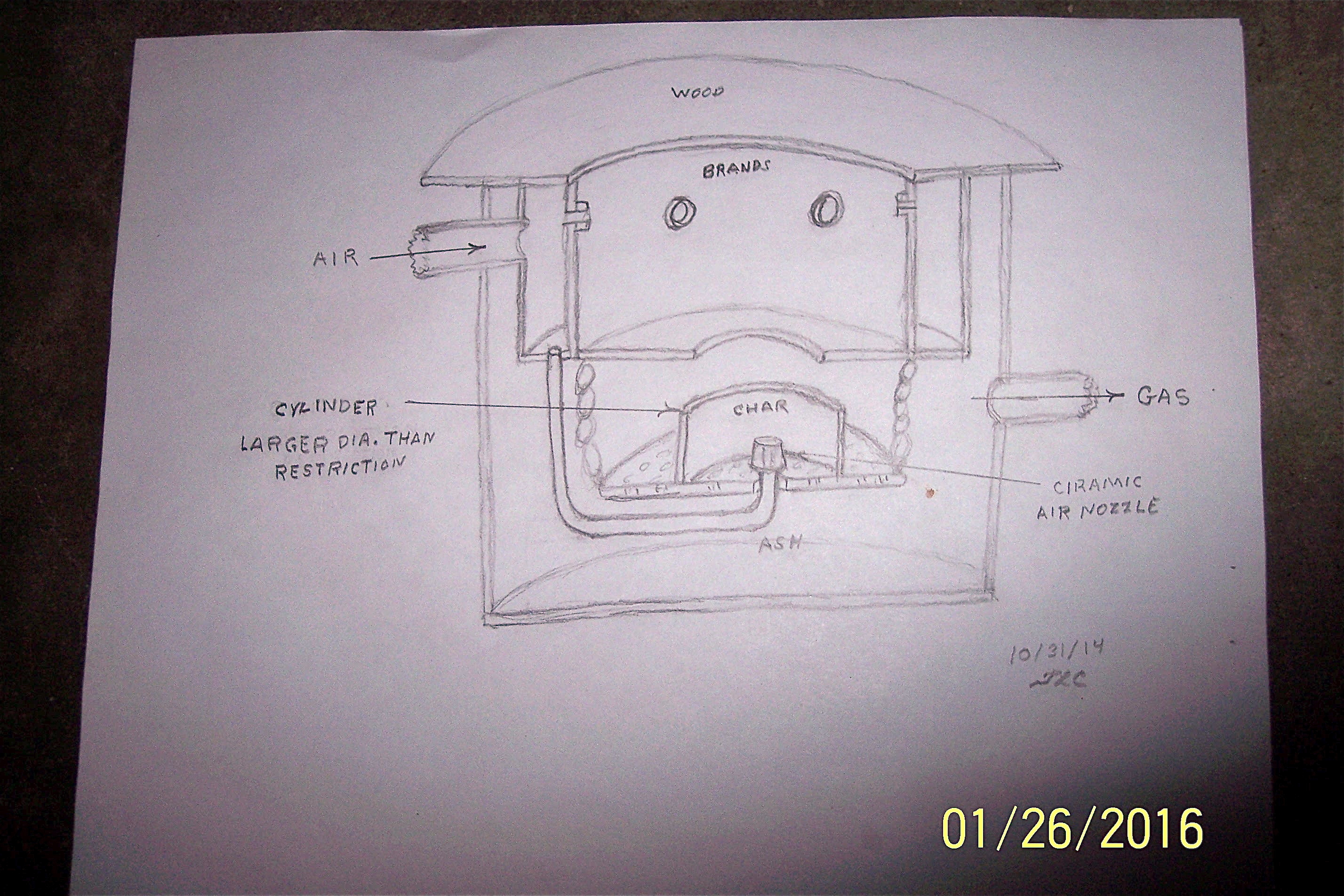
The central “focus” point in laying bed gasifiers is the restriction.
Increasing air and gas flow need extended “working” volumes.

For oxidation upwards, and for reduction downwards, seemingly; reduction in bit size, especially downwards can compensate for a physical space, if you win the battle against ash!

There seems to to be two ways to go:
Physically bumping grates, sieving grates or increasing the gas velocity in the ever smaller “grains” of char.

A competely other approach is “cyclone gasification”…

…

Now, in a laying bed, the increase in volume upward seems to be free from jamming any mechanism, when using a protected slide for switching nozzles at different heights.
In a double heart wall a rotating (part circle movement) slide can switch different nozzle groups on and off.

It can be tangentially moved with a rod laying in a cylindrical flat “grinding stone”-formed slice, connected to an outer double cylinder.

Between the two double cylinders ash is giving insulation.

Air is fed to the outer double wall cylinder, passing down to the “grinding stone” and up in the inner double wall hearth.

The push-pull rod is taken out throgh a short “tunnel”-tube from the “grinding-stone” perphery through the outer wall of the gasifier, flexibly and gas/air tight!

Futuristic???

4 Likes

Where do you come up with all this stuff??? I am aware that there are server patented types of gasifiers coming out of WWII. From your description, it seems to me that we are all following the GMR paten — [quote=“gasman, post:11, topic:2677”]
Upper throat, where the nozzles are situated, lower throat = the restriction
[/quote]

I take it that this design came out as the best all round design, but are there any significant benefits from the others that we maybe should be looking at. The single throughtt appears to be very simplistic and the “stone type” plate seems like something the driver has to keep playing with durning a drive. Interesting information, though. TomC

1 Like

Arvid l apologise with reduction l ment restriction. I will be puting secondary air on the restriction.

Well the benefits of this as l see them are less tar, less CO2, less water and more calories of gas. Think of this like it is a combo of a wood and charcoal gasifier. We all know the benefits of charcoal gasifiers but to make a sistem that combines them with ease of prepareing fuel like a wood gasifier it is a pure win.

Max do you have any documentation about that topic? I didnt realise this already exists untill you mentioned it.

2 Likes

Hi, Tom!
13. August 2016

The tangential rod, for switching the nozzle groups slide can easily be done by switching solenoids, switched at the dashboard.

Only lower nozzles with smaller tip-circle-diameter and smaller holes, when you arrive to low-speed town districts and the highest on, when you come out of towns to free roads…

Nozzle-tip-circles following the 60 degree avalanche cone…

1 Like

Kristijan!
13.8.2016

“There is nothing new under the sun…”
If you mean Imbert FSD, look at patents in Paris, beginning of July 1944.

And this is primary air! The motor gets the secondary air…

2 Likes

Max/ Kristijanl Could it be K is talking about something like this. I know I posted it one other time and you said it didn’t come from you Max, but somewhere on my notes I had your name written.

Tom, Bruce has been living with a nice woman for several years …I hope it is her :o) WE stayed with them last year … Mike
Still have 3 broken ribs … slowing me down …

Kristian, I do something similar to what you describe… I have an upper nozzle circle and then one more lower nozzle pointed at my hot well, like what Stephen Abaddess does with his Victoria gasifier. Look around at his posts he pretty much showed everything he’s doing. My systems are based on his hearth ideas.

I’m sure I’ve posted pics hear of my inners (hearth build up) but not my preheat and grate.

Tom your skech looks interasing too but l think it has one drawback. Ash.
The plan is to put nozzles on top of the restriction to make kind of “doors of hell” for the tars and other unwanted things. Just a portion of air will actualy go there, most still doeing on the main nozzles.
In wich topic did you post them Arvid?

Had some progress today but this whole idea got me thinking. I was planing to put a 3" restriction in for a start, but l think this wuld be to small for this sistem, becouse second sets of nozzles shuld burn more charcoal, eventualy leading to s cavity betweed oxidation and reduction zone. Any thods?

Ps the engine will be 1.6l 16v 109hp rpm at 100kmh (63mph) at 2850rpm, usualy driven at 2500rpm.

1 Like

Probably my case tractor build.

3"restriction would be ball park.

1 Like