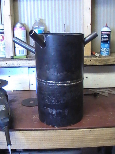
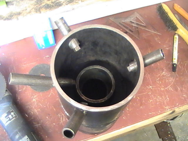
That should give you an idea of my nozzle orientation
That should give you an idea of my nozzle orientation
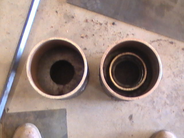
Picture on right is looking at the bottem end of the hearth / reduction zone area
I’m glad somebody is still building !!! I’m using most of my wood right now to bake potatoes and roast sweet corn … Recovering from the argos coma … Just fixed brake lines on my black truck so may take a drive soon… It’s ready , Mike
K; My posting of that drawing was not to suggest that design. I just thought it sounded like what you were describing. I am a visual person and have to draw the words out into a sketch to make sense.
I would suggest a regular Imbert design dimensioned to your engine. Then go to JO"s 8" gasifier and follow the discussion on the reduction zone. Over the years that has just been an area where gas passes through and what happens happens. How ever after reading the discussions between Max and JO, I am putting more importance on the reduction. If the oxidation figures are followed correctly, you will develop enough heat in the oxidation area to sustain the reduction to completion, with the proper design reduction area. An improper designed reduction area and you will end up with a lot of un reacted char, wasted heat, and probably a diluted gas with more CO2. TomC
PS. I just remembered that you are leaning to “chips”. Never tried them but others have and there are particular problems to making the flow through the system, so I revert to the King of Chips Mr. Arvid. But I still think after seeing his oxidation zone, that the reduction zone must be a point of attention. Sorry, Those look like some rally workable chips. Rather large for chips which is good.
Hi Tom,
You have a nice way to turn your sketches into understandable words, love it.
I think that Kristijan’s focus is exactly the reduction zone and the problems there.
I love his approach and learning from all of the reply’s he’s getting, maybe one day soon i will start building one myself… but i still have a lot to learn.
I am thinking off a charcoal gasifier with on top a “Don style” charcoaling unit… 
The main challenge , imho, is indeed the reduction zone, hot glowing charcoal able to reduce all volatiles into useful gasses. And how to manage that process…
I guess, a lot is depending the input material…
So its ok? Sorry l dont know what a ball park is 
The imbert dimension table shows a 4" restriction for this but l know JO has a 3" on his build with a similar engine. Culd someone explayn this a bit? l thrust poeple more over a paper.
Arvid so you use 3 main nozzles + 1 to the restriction?
Tom my fuel of choice is chunks. I havent yet got a chunker but wanted do build the gasifier firt to show me what she likes to eat.
Koen im glad you allso see the potential. We are lucky to have experiances with the power charcoal chemicaly. This got me the idea (althugh it seems l am not the first to come up with it). l like to look at this as a charcoal gasifier with a charcoal makeing retort on top 
Kristijan,
I´m now at 3.5". No signs of tar.
Thanks, will put that in consideration!
I could`t agree more
I had to look it up, but it means acceptable range or approximation. The English language has some sayings that don’t make sense unless you know the background. (Don’t ask me what background means). 
3 inches may be better. 2.5 may be a little small.
You’re looking at around 12-13L /second of woodgas.
Yes my small systems have a total of 4 nozzles.
I tend to build things on the smaller side. The Case tractor has a 2.5 restriction in it. I suspect its gasifier would run your car without any problems
Yeah, start small. I started off with 2.5", then 3" and now 3.5".
Confirmed.
I have a 120 L hayfilter. When I shut down for no more than 15-20 min I usually start right up on “old” woodgas with the same air setting as I left it with. After accelerating for 10 s it starts to hesitate for another few seconds.
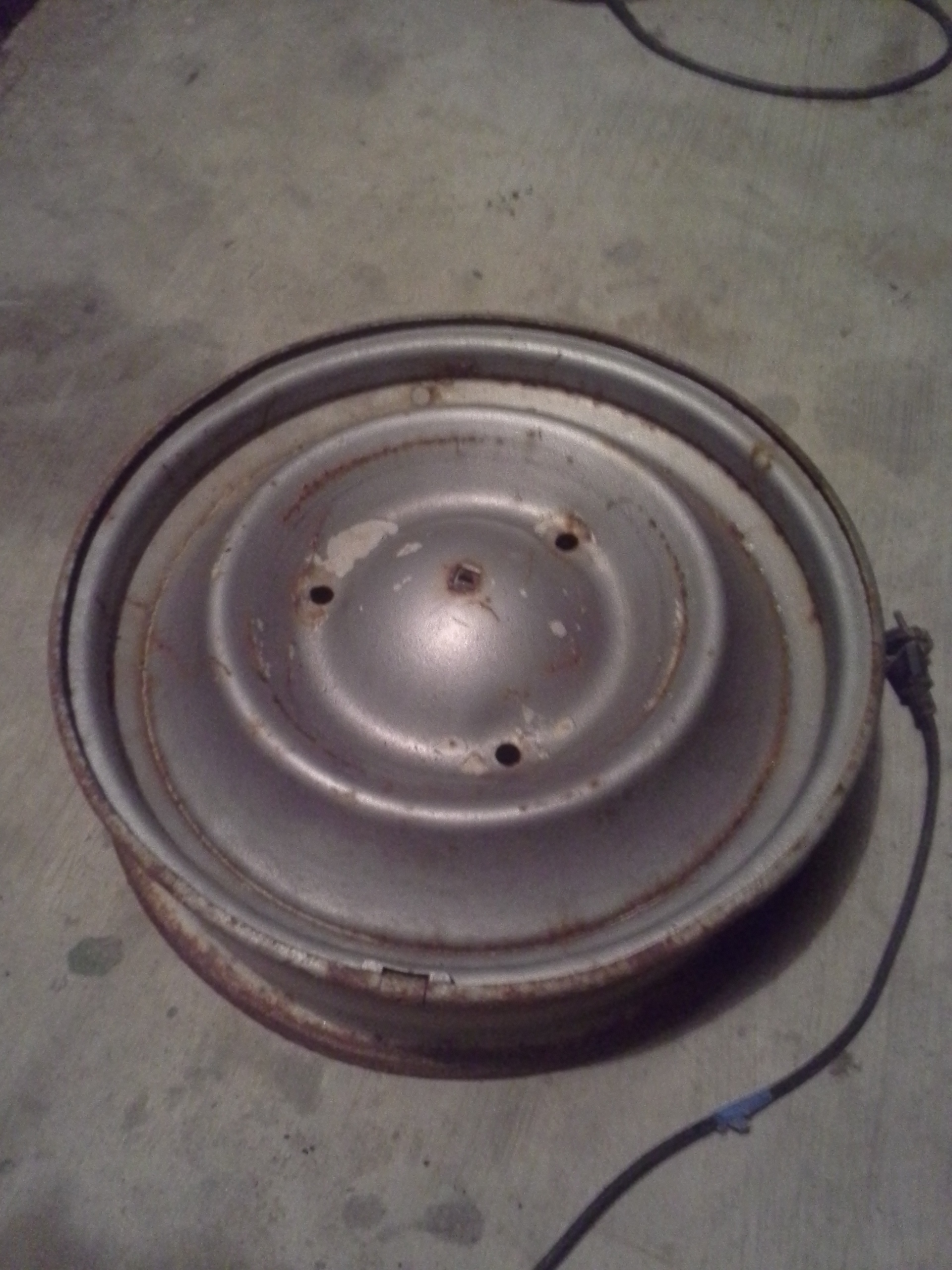
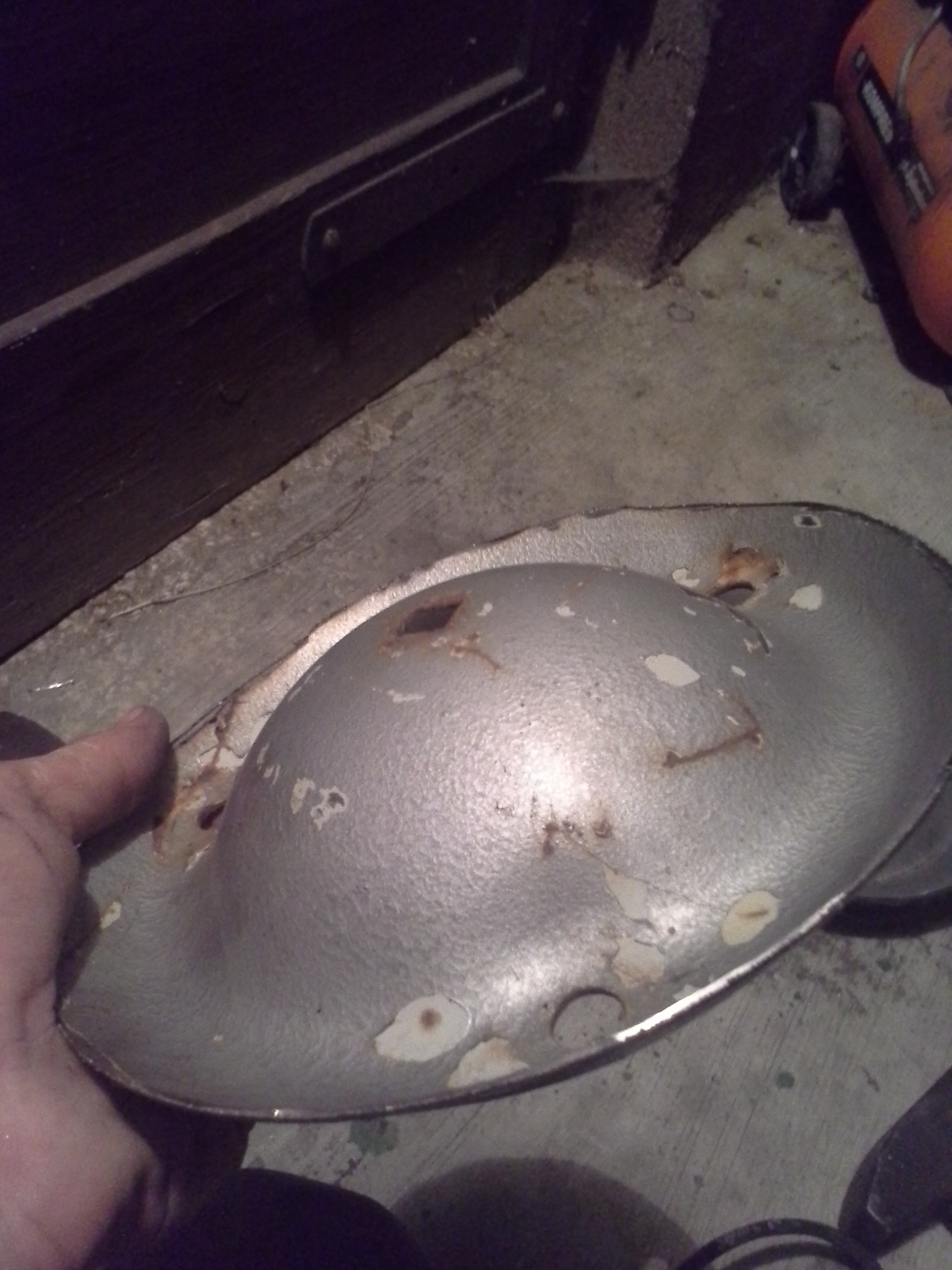
Scored good today. Found this old (VW?) wheel,
l made a 3.5"restriction since it is the only dimension l had on hand. Will make an insert to put in a 3" if neaded.
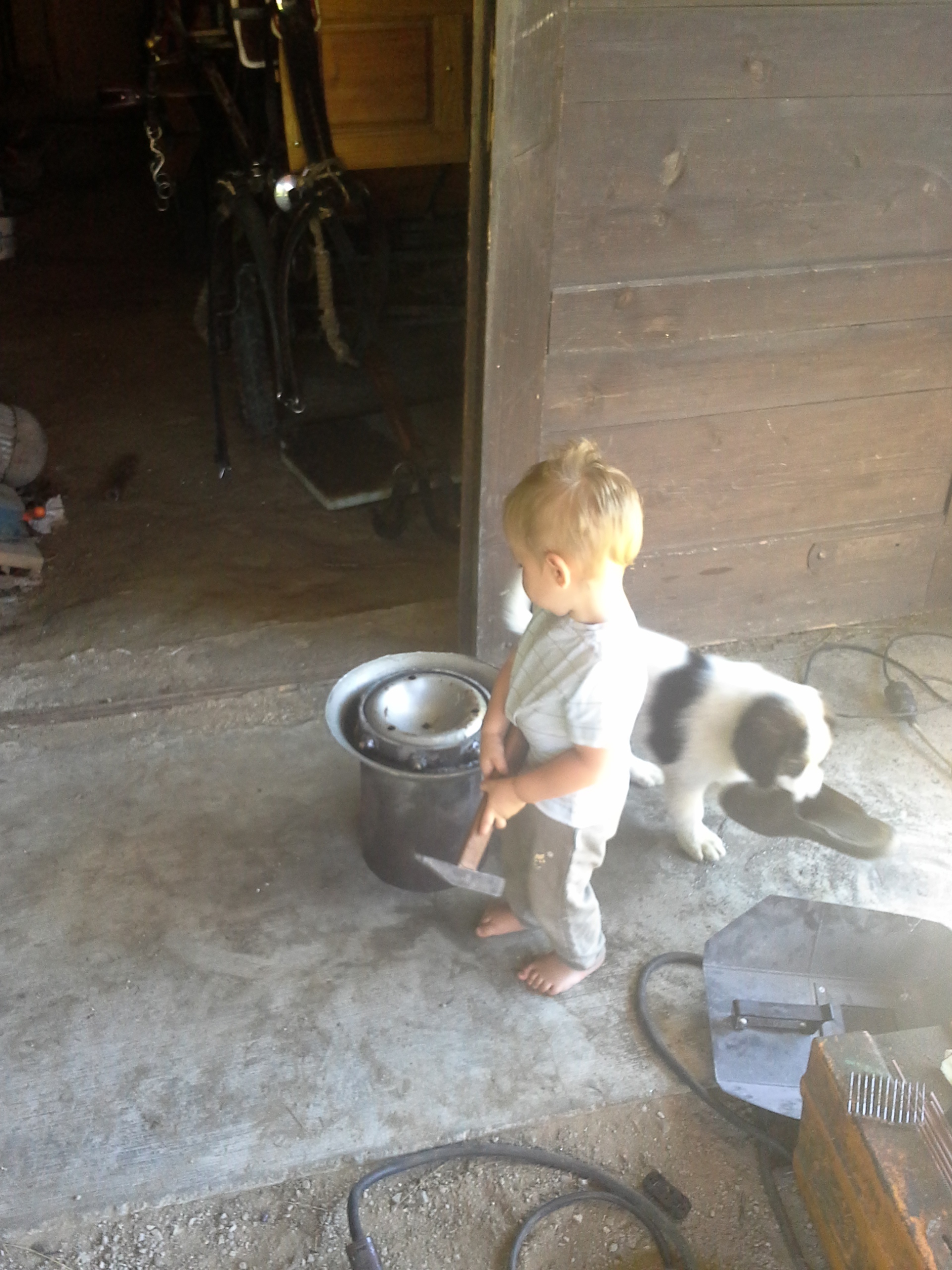
Culdnt do it without my helpers thugh 
Looking good Kristian!
Watch out! We’re following your every move.
I can see you let the shortest person handle the most important tool 
Those helpers are about the same age (if we take dogs age in to count) you can just imagine how fast work gets done with them around
Hi,Krisijan!
15. of August 2016
Slitz! Not holes! 1:3 – 1:4 as a proportion…
Chisel a cut, and bend the edges upward, to contain protective ash between the slitzes!
Heat by gas-oxy-tortch the spot yellow-red just before chiseling.
Or use a thin cutter disk. What bends as well as cuts is the aim.
Those look more like Citroen 2CV? 3 bolts? VW 5 bolts!
With 1:3 you mean what? You make sense (as slways) with edges bent upward. Will do that. What shuld the dimensions be? I was thinking 3-4mm wide with a total sume of the restriction surface (Arvids advice).
You are right Max, it was a citroen!
I mean the proportion breath X length!
Width = ~10 – 12 mm … lenght 25–40mm
The upward bent edges can be bent back if you see too much small bits pulling through!
But the first aim is to get FLOW!
My open slots are 1/2" (12-13mm) wide. Seems to slip just the wanted amount of char without chaking. I think 3-4 mm are way too small. It’s easier to get plugged than one can imagine. However my former plugging was not the grate. It was a too tall reduction. Everything is a balancing act as usual.
JO did you correct your problem with ash clogging?