Good point.
On all of the above.
This tarry gas passing between the nozzles is what l am currently trying to eliminate. Will see.
Oh, l forgot all about you haveing sacrificial plates. How are they holding on? Any sign of them wearing out?
Good point.
On all of the above.
This tarry gas passing between the nozzles is what l am currently trying to eliminate. Will see.
Oh, l forgot all about you haveing sacrificial plates. How are they holding on? Any sign of them wearing out?
This picture is from when I installed the sacrificial plates. They hold on only by the nozzles and brackets. The burntube was later cut off the same hight as the plates.
I haven’t checked them out since before christmas but I saw no wear on them at that point. I think ss may have lower melting point, but it seems it doesn’t flake from high heat. So far so good.
In KristiansK’s first illustration ~9 posts above . . .
undercut the slope and extend it to nozzle face to create an underslope cavity. Now make the upper orange flow arrows circular.
As Max G said the trapped pyrolis gasses will be held here circulating and drawn back out to the nozzle face active area for long chains breaking down.
Heat and turbulence oxidized then into reduction area input gases of CO2 and H2O HOT vapors. AND MORE oxidization zone created system heat!
I have seen this “system” work well even with flush mounted nozzle faces so long as that overhanging cone space is formed.
Cone slope will get HOT. Vaporizing upper system dripping down tars. Tars dripping down off the cone edge falling right in front of the nozzles blast.
Nope. No names, named. I get myself in enough hot water as is. System illustrations and pictures will show who is doing this intentionally/unintentionally.
As said this will greatly expand the turndown ratio of a system.
J-I-C Steve Unruh
Hi Kristijan, my plates are looking good. The only thing to remember is make sure you have two opposite flats cuts on any circular choke plate or disk you use, so you can remove them. My plates are bolted at the top and have a little gap behind them at the bottom from the high heat. With 12 of them in place I lost about a 1/2" of diameter at the bottom from heat. Better to have the plates to take all the heat than the fire tube wall. I cut my circumstances on my choke plates smaller also. The ash fills in the voids.
Bob
High, Kristijan @ All!
7.3.2017
This principal, with injecting nozzles has been used in south-western Finland during the 40-ties, commercially…
The only backdraw is, that the return gas from the silo-condenser is cool, and 100% wet; negative factors for airblasts!
The blasting “fresh” air is dryer, but their mix is heat consuming.
Hi guys,
I decided to take the gasifier apart the other day, only to find some major leaks and pinholes on the welds on the gasifiers air manifold. No wonder l had bad performance in a hot gasifier lately.
So, l was looking at the gasifier, thinking to my self l have two options. Repair the prooven gasifier, put it back together and drive untill there is a problem again,
or learn from the mistakes and experiances, and make a new, better (hopefuly) sistem.
You can guess what l decided for, so after a lot of thinking l threw my cards on the table.
Things l need to make better:
-shorten the hearth, in order to gain space for hopper height.
-make the hearth as tar free as possible
-make the whole thing lighter
-make better filtration, in order to save engines intake manifold sooting
I like the WK gasifier a lot. It has many features that the lmbert doesent, but there is one great disadvantige of it, and that is the leangh of the firetube.
The alubox determines the max height of the sistem, and that is 60cm above the platform. Now, l had a firetube about 30cm long, so that left me only about 25cm of hopper height. Not much at all…
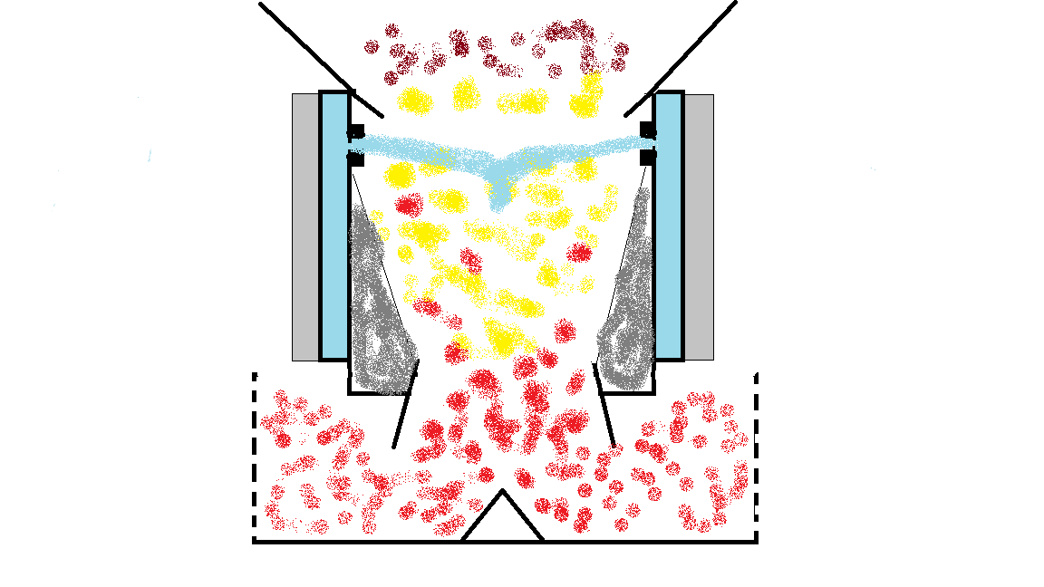
So, this is what l came up with
The features of the new design are the new GEK inspired reduction zone flows horizontaly instead of verticaly, lowering the sistem considerably.
The air preheat shuld feed the gasifier with hotter air, and allso aid ti the flywheel effect.
The overhanging balcony shuld provide a turbolent enviroment for the pirolisis gases to burn completely.
The cooling fins from the air intake manifold (coloured grey on the picture) shuld cool the reduced gas soon, in order to prevent it to break down to soot and CO2 due to natural phenomenom of CO brakedown under high temp.
This said, there is only one more feature left to mention.
I was thinking… In a imbert, we have a strongly turbolent enviroment. While this helps the combustion of tars, it allso has a week point. The turbolent gasses can escape in the lower part of the gasifier between and behind the air nozzles unoxidized. So, l came up with a design that has only one nozzle, (or none at all?) trugh the whole plane of the oxidation zone. Just a gap in the firetube, to alow a high speed blanket of hot air to oxidise all the taks produced.
The gap its self is shealded a bit with two forged 1x1cm steel rims, surrounding the airgap.
Folowing the clasic lmbert dimensions for the air nozzle surface area, there fore air velocity, placed in the form of a air blanket, l think the tars have no chance!
If my plans are right, l culd manage to get trugh with firetube height of about 15cm in the alubox, leaveing me 45 cm of hopper space. A conciderable difference!
l have everithing prepared for the new hearth, a few welds and we are up to the next point.
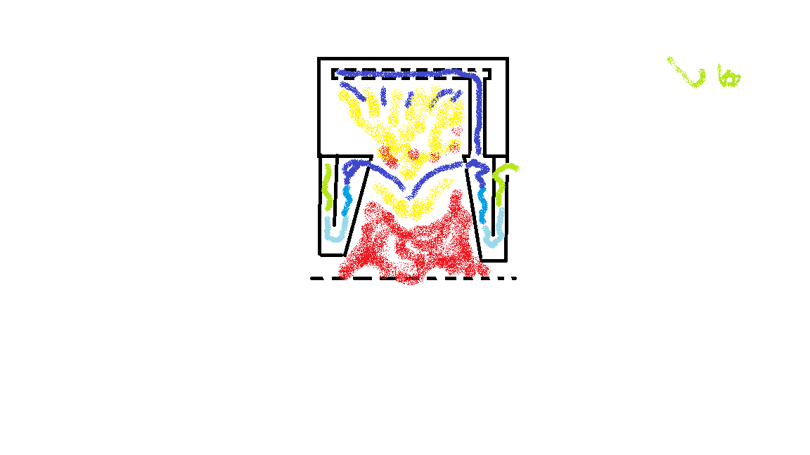
This is a nother one l came up with, @Chris you are free to move or delete it if you wish (it has nome wk features)
A double throat tar free wk Imbert 
but for now, lll stick with the first one.
Hi, Kristijan!
10.3.2017!
Glad to see the wheels turning!
2 starting comments:
1924 George Imbert patented his first woodgas 4-nozzle gasifier.
It had an upstreaming solid-wall “basket” reduction zone, concentric around the hearth.
1926 George Imbert patented his first straight “firetube” gasifier, which had a ring-slitz for air distribution just under the silo-funnel… but no balcony-ring.
“Nothing is new under the sun”… it seams…
1929 George Imbert returned to nozzles, (his favorite 5) for better penetration of the center part of the hearth.
…
In your first proposal I would leave no part of the reduction tube “naked” and outside the heath tube’s protection ash!
Turning the narrow end downward for increasing velocity and fighting ash clogging! (moderate)
Bottom insulated!
Tube end at least 0,3 diameters abowe bottom insulation.
The hearth double-wall outer “skin” as a “star” seen vertically; the air-side of beams = 3 to 4 mm, the gas-side = 15 to 20 mm because the outside will otherwise clogg fast.
“Buckled” from 0,8 - 1,5 mm SS. Beams 30 - 50 mm long (horizontally)
“No Flow” along the center tube! Inserted (short 50 – 100 mm) , (thick ~10 mm) cylindrical ring between the inner tube and the inside of the “star” gives peripheral distribution of air in (down) and (abowe) to the nozzles.
The ALU box is preferably displaced by a ventilating tube-wall box.
Max, thanks for the reply and a useful and interassting history lesson!
I was thinking about air curtain penetration, but with my size of “the ring of fire” (l culdnt help my self but to sing that good old Johnny Cashs song all he tiime when l forged them  ) l think it shuld be good.
The basket reduction has perforated botom right?
I put that cone out trugh the insulated firetube inenioly, to have least possibe heat loss back up from the reduction char, but now that you menioned it, l think l culd find a way to insulate it and make it flush.
The bottom l plan to insulate with siporex, carved to desired shape and size. Wery light, insulative and fire resistant. Allso disposible.
I plan to mount a thermostat operated car radiator fan on the front side of the alubox and go with the condenseing hopper. Hide it with a nice grill.
Allso, the filtration and cooling will be different.
A scheme:
Gasifier, cyclone, hot filter, small cooler, semi hot towel filter, final cooler on the front side of the alubox with the condense tank.
Kristijan,
This will be interesting! Keep us posted!

Kristijan, I like that a lot and I’m so envious - both you and Wayne have green grass. I won’t be in welding season for another mounth or two.
Ha! The apricots and peaches are just a few days from bluming! I love spring…
But with warm days comes loads of work, so l sugest you enjoy your office next to the woodgas boiler and a can of beer for a litle while 
Yeah, I’ve seen them on post cards. We’ll get carrots and apples in August - right before frost…
Good Morning KristijanL.
On your first design . . . the oxidization-to-reduction “throat” is the true ring-of-fire high erosion piece.
If you make this as a drop on plate with your reverse cone-hole welded on to it, you will be able to pullout and replace easy in service.
How many do this. You are experienced advanced enough to know that this WILL gas tight ash seal!!
And then you can just then pull our drop in different dimensions fine tuning for results.
Regards
J-I-C Steve Unruh
Steve, very good tip, but unfortunaly a hour too late  aleady wealded. Althugh luckly l went with a wide restriction (9.5cm) so there is enough room for a insert.
The gasifier is desighned to have easy acces from both top and bottom.
A question thuh… as Jan pointed out some posts ago, is there any point to put in a oerhanging balcony in such a small gasifier? I am a bit affraid of bridgeing…
I have the allpowerlabs grid tie power pallet . I was to have gotten version 5 but got version 4 . It arrived burnt out , broken and seized with tar … I wanted a refund . Allpowerlabs wanted another $10,000 to send out tech . After three years I got it working . I capped the air inlet . I used the lighter tube as air inlet , I extended lighter tube to same height as air nozzles ,
put on gate valve to restrict air going through lighter tube . Actually works now
Hello KristijanL.
On Dutch John’s MicroGasifier site sub-chapter look at his line-illustration of his tiniest gasifier for his lawn mower. ~1/4 the size of yours I believe.
Look at his just above the jets transition “pyrolisis cone”.
This used a graded screen wood chip described in the text.
You could quiz him on bridging problems.
www.woodgas.nl
Regards
J-I-C Steve Unruh
I have some observation when i make charcoal in the retort system…
some Tar leaving the hot retort is not even gas but a sirup like liquid, the colder it gets the more sticky, but never gas untill it burns away in hot charcoal or open fire.
I use this observation to “separate”, in different stages, the quality’s from the wood vinegar
If you have more of these tar’s then average, then maybe a drip guidance / balcony / funneling could guide that tar just in front of the nozzle tip / blast zone ?
Hi, Kristijan!
12.2.2017
Sorry for being a bit harsh, even after some concideration, but:
It took George Imbert 3 years to abandon his slitz-ring air feed in a narrow and long firetube, “landing” on a charcoal bed.
You have a broad and short one; about 70 – 80 X 3 mm holes blowing through a sloppy slitz around the perifery.
For you it will take 3 hours — not 3 years to see that the center region will perform like a tar cookery!
To get a white-glow center asks for determined “hosekeeping” with the airflow at disposal… ~60% of cold delivered gas…
Everything is now dependent on how much oxygen can reach the spot just abowe the entrance of the restriction — that will hardly happen on idle and low power…
Then the balcony lower edge should not be dripping tar on the nozzle-tips (making coke and passing down by!) but place their dripping 10 – 15 mm further in towards the center!
That way the tar lands in white-glowing char and the right reactions happen!
Don’t worry about fuel clogging, a mobile gasifier chars the surface of the woodbits abowe the nozzles if you offer a tight and hot nozzle-tip circle; ~0,7 m/s imaginary vertical flow in the tip-circle!
Relaxing and listening…