Leitinger wood gasifier

Hi, Kristijan!
6.4.2017

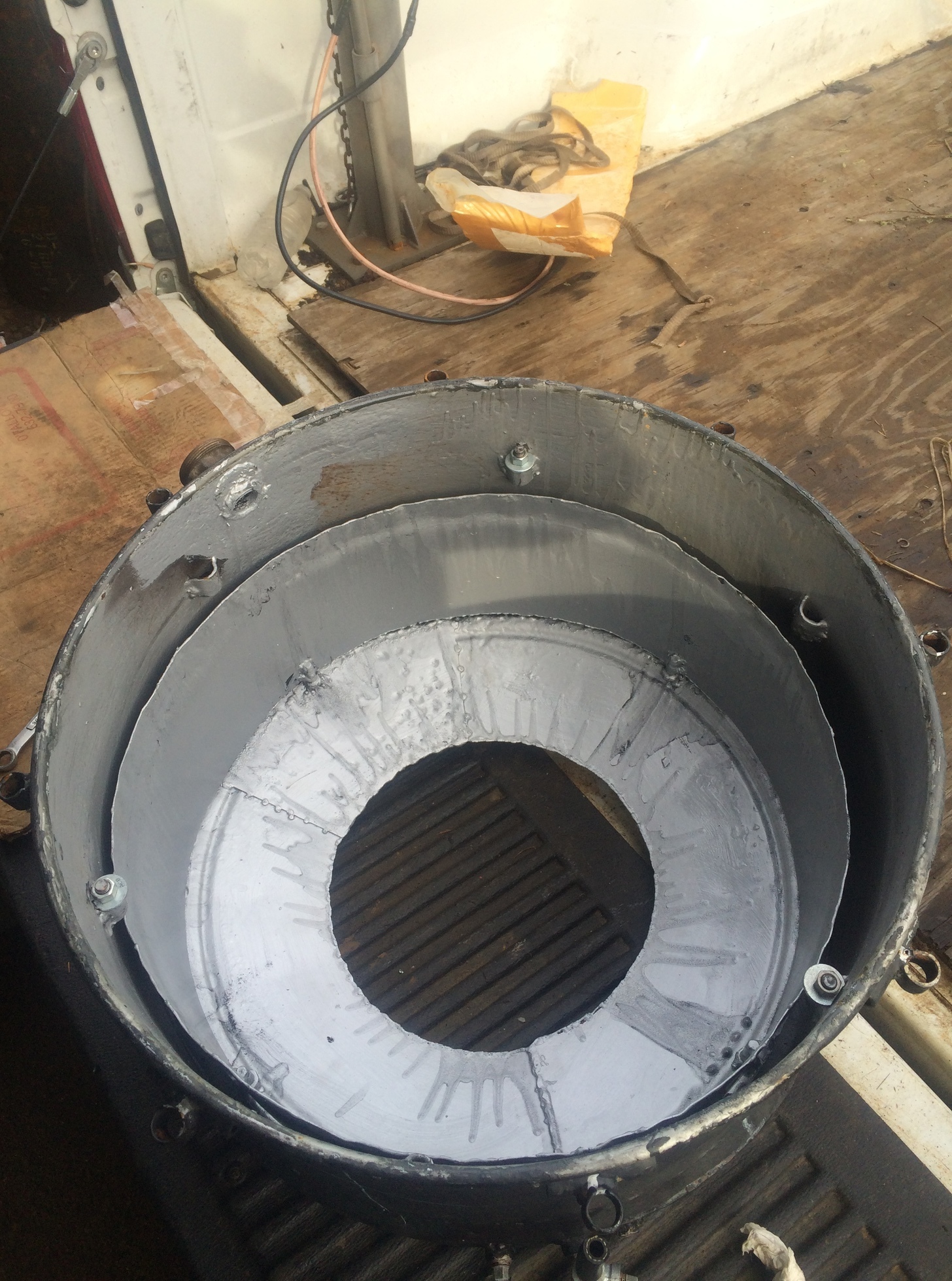
On mess. 923 you observed that only a “patch” above the restriction entrance is glowing bright despite that all the hearth-area gets equal supply of air, when you have had the lid open for a while.
That is nothing strange! The sides around the glowing center-patch have almost
no draft!

However much air is available above the fuel level, the combustion needs draft through the fuel to glow!

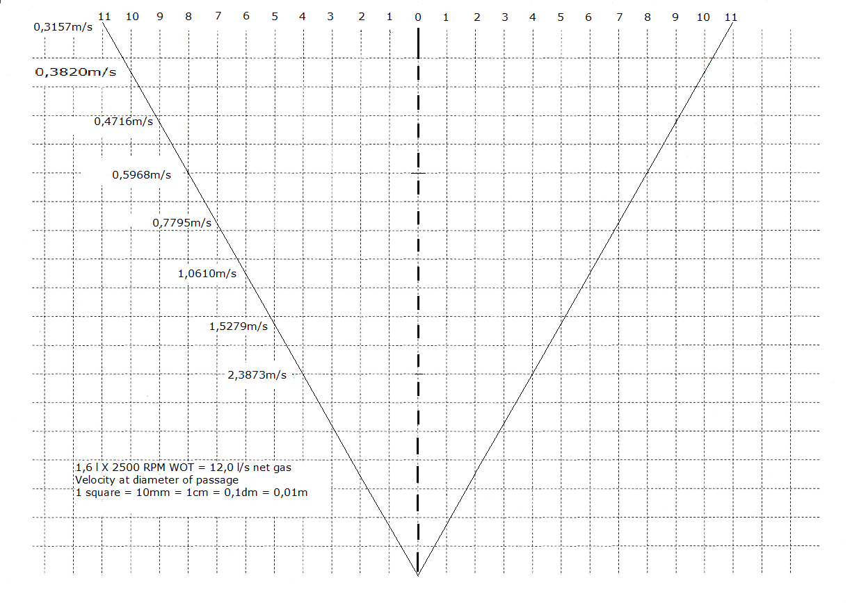
The minimum draft is ~0,5 m/s to keep a fire going!

When the gas demand increases the glow would spread out as long as the increased draft can support a diameter and volume of the “glow-patch” increase.
This will take time, and as you observed, there was not a fast enough response to a fast increase on gas demand…

Now, the uppermost (highest) nozzle row has the task of setting the maximum oxidation volume for top demand.
At “full blow” the oxidation should end at the restriction entrance.
At idle, it happens higher up, and the reduction draft is low above the restriction = cool and weak reduction.

Many’ a constructor has tried out to put smaller-hole nozzles nearer the restriction, but done nothing to control the floppy flow at main nozzles during idle.

To be effective, the main nozzles should be cut out and taken over by an equal in number smole-hole nozzles to sustain a “heart-function” in the upper end.
At the same time the lower end nearer the restriction
should have the same count of small nozzles blasting.

The idea is to retain blast temperatures at the reduction entrance and a live standby top level.

At idle we can use high motor vacuum to get high blastings with the small-nozzles rings, but that asks for cut-off control of the main nozzles,

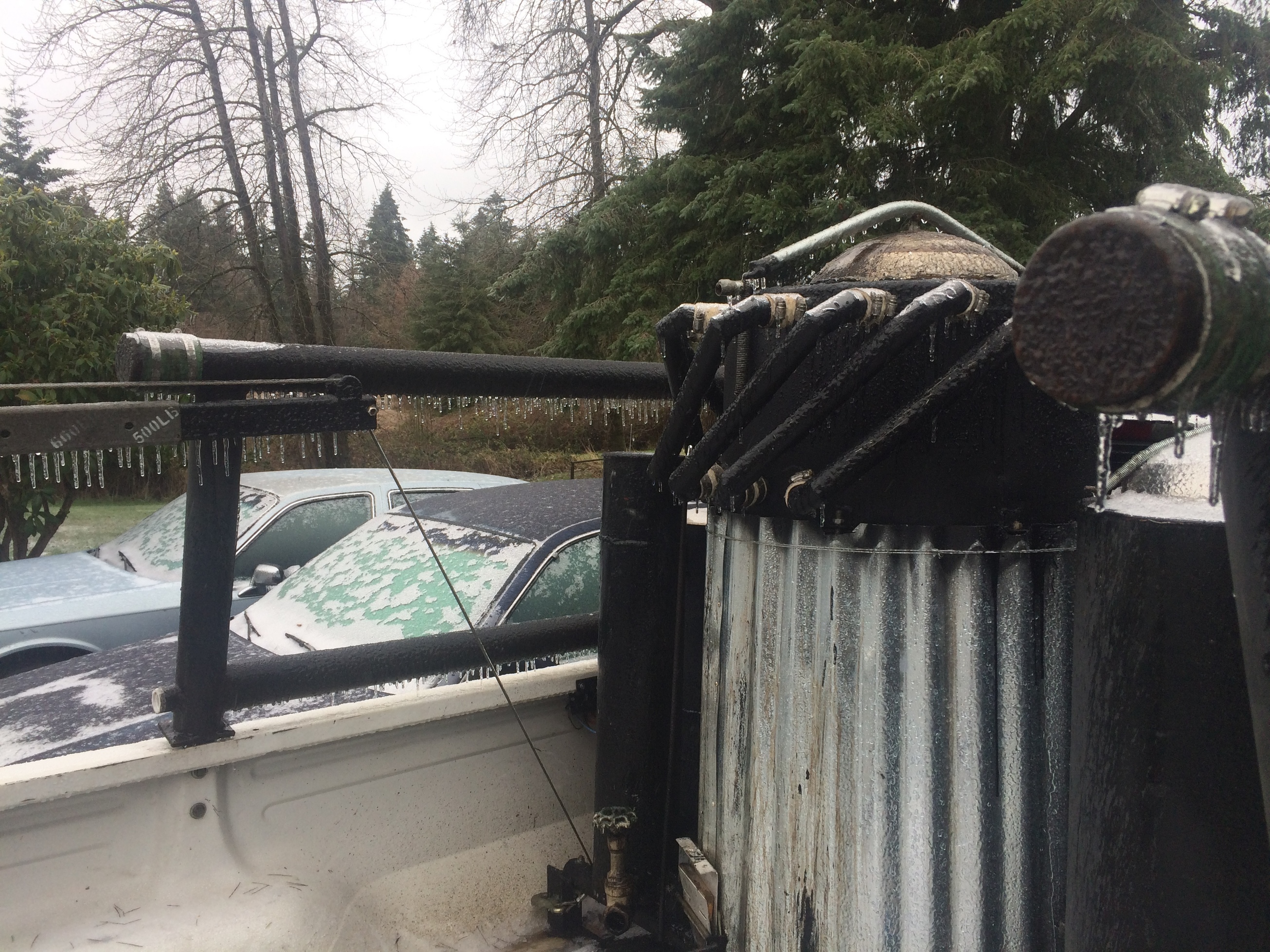
AND Reinforced filter barrels!

Reason in all! Normally 4 to 6 in of H20 is giving good blasting, so double this would go a long way on idle.

As soon as the normal nozzles are “let loose” all is back to normal for drive. The small ones need no arrangements.

Koen, l am still a big fan of the secondairy air nozzles on the restriction top, just not compatible with my low design.

Max, l like the lighting port idea!

1 Like

Hi, Kristijan!
7.4.2017
Message 941 is available…

Max,

Those are some preety smat and advanced words you put down. Thank you.

I was thinkin of controling the nozzle flow on different heights before but abandoned the idea becouse l saw to much complexity to proceed. It looks like l was wrong.

Ok my first idea in how to make the idle to drive transition is make a spring loaded diafragm valve operated with engine vacuum. Idle-high vacuum- shuts main nozzles off. WOT-low vacuum-diafragm opens all the nozzles. Kind of like the diafragm timing advance sistem.

Will definitly put some thod to it! But first, a condensing hopper.

2 Likes

Max,
I just got the picture of the grate construction in my head! :construction_worker:

2 Likes

Hi, Kristijan!
7.4.2017

Thanks for the overwhelming comment; these are just observations made of how gas-emitting-hot and cooler wood behaves!
The gas-emitting hot wood is re-lightened in a snap, while cooler wood has to be re-heated before it can support a flame, when air is “offered”.

Taking intake manifold vacuum as a signal criterium, is a bit vague, as the gasifier already is under considerable vacuum succing through the 2 smaller-nozzle rows…

The positions of flaps are independent of vacuum developments, and can directly manouver microswithes.

The small-nozzle row near the main nozzles are there to guarantee fast reignitability after a longer idle.
They work like “pilot” flames.

The lower small-nozzle row has a “harder than normal” working condition; it has to handle the pyrolysis “cloud”
now streaming down from above boiling wood.

Let’s see what the idle air flow looks like, before “selling” or “auctioning” the flow areas for different nozzles!


Cold & Empty flows according to the
Royal Academy of Science in Stockholm
in the book Gengas

Enlargements as multiples of the Kelvin 273,15 deg. Celsius “segments”… starting from abs. 0 point.

“everyday” formula with main factors baked-in:

WOT: l X n X 3

expressing liters per second net gas at WOT

l = liter displacement
n = RPM : 1000
3 = baked-in constant factors

ex: 2500 RPM : 1000 = 2,5

(the 1000 is already baked-in into the constant factors)

1,6 X 3 X 3 = 14,4 l/s … l net gas/s at WOT

1,6 X 1 X 3 = 4,8 l/s … WOT X (1- 0,65 atm = 0,35) =

1,68 l/s net idle gas consumption.

The cool air needed for this production is: 60%
of the cool gas.

1,68 X 0,6 = 1,008 liter/s

So, the idle air flow is about 1 l/s

The full flow air is 14,4 X 60% = 8,64 l/s

The full flow has to include the idle air flow,

as the small nozzles are never closed!

Now, we have to “auction” 1 l/s air flow for both sets of idle nozzles together.

I propose 1/3 for the top set and 2/3 for he lower ones.

meaning 0,33 l/s for the top ones’
and 0,66 l/s for the lower ones’.

Actual nozzle flow areas and velocities…

I am taking a pause and listening to comments…

8.4.2017

Are the 3 mm holes 35 or 45 ?

I find it difficult to apply the nozzle-switching system without “ripping up” a lot of the two surrounding cylinders around the hearth tube.
Eaven then, the sevicing of the switch-slide would be hard to perform. Perhaps in next build, where it is taken into account when planning.

If done now, the upper part of the air mantel has to be separated below the nozzles from the rest of the mantel, and then fed through an outside valve from the lower, separated part.

The hard part is still those 35 or 45 3 mm holes, which are “bleeding” in air, making any blasting pressures impossible to achieve for any small nozzles at idle!

Still, you need to put in heat insulation between the new silo and the heart mantle-part, otherwise the condensing will only be a dream…

2 Likes

Max,

I was thinking how to calculate gas consumption at idle, of corse! With pressure difference! Thank you.

Max, in this video you can see some dimensions.

As you can see, the only way to make idle nozzles possible is install a nother set near the restriction. The makin nozzles are just a inch apart.

11 Likes

Nice work Kristijan!
Make sure, besides circulation, that you get some hot air out of the alu box and cool air in towards the hopper walls.
I admire you determination. I don’t seem to get anything done myself. I should have done a baked tar cleanout below the lower funnel for a long time now. I’ve been running around at 80km/h emptying more than half my condensation post gasification. I expect to get the upper 10% of power back as soon as I get it done.

2 Likes

i want to keep clicking on the like button…

3 Likes

Hi, Kristijan!
8.4.2017

946 is continued!

Hi, Kristijan!
10.4.2017

Have you gone into a meditative, replanning phase of solving the air distribution?
If the hearth undergoes “rescaling”, perhaps there is some help of a flow/velocity diagram I composed this night…
It is based on your once expressed statement, that you hardly go over 2500 RPM on the better roads…
The velocities aim at diameters in eaven cm.

Right, when the NCH converter at last was convinced!

3 Likes

Hi Max,

Took a day off celebrateing my sons second birthsday.

Thank you for the diagram. What shuld the optimal velocitys be?

No, for now l will stick with this hearth. I havent eaven tested it properly!

2 Likes

Hi, Krisijan!
10.4.2017

“Postcongratulations” and many happy returns!

Many factors affect the choise; fuel size and humidity, driving short or long distances, condesing mantel or not affect the top nozzle-tip circel vertical passage diameter. Preheat or not…
The colder and more heat needing (humidity) the tighter the diameter: On GMR Imbert around 0,6–0,65m/s, I use 0,95m/s with a fuel heating Imbert mantel.
No real air-preheating.
The general impression is, that there is always a need for more preheating and condensing, affecting the next start.

The volume between the top nozzles and restriction is most affected by wood-bit size.

GENGAS trucs and busses ~11% 7 – 11 liter motors!
Light loaded grassclipper (DJ) 4%,
My case ~5–6%,
A mostly fast road hard-driven Volvo 2,3 liter has 7%
of the liters per second net gas consumption. (At WOT)

Everything between the consumption and the fuel size!

2 Likes

Hello Max. I know you do not like to re-explain things that you feel are evident , so rather than getting upset with me, just ignore this post and go on. But now I realize that your knowledge is so much greater than mine, that my questions, to you, are juvenile.
So first, you are talking about setting the nozzle tip diameter? I thought that I had recently read how to calculate the meters/ sec of the air/gas flow in an Imbert style gasifier. I “assume” that if I do that calculation for your engine, I should come up with 0.6–0.65 m/s. You changed your value to 0.95 m/s. How did you know that mantel design would change the velocity by 30%? ( again I am assuming that m/s is a velocity equal to{?] [quote=“gasman, post:955, topic:2677”]
the top nozzle-tip circel vertical passage diameter
[/quote]

Then you take a percentage of this value of m/s. That percentage varies from about4% for DJ Tiny, to 11% for a lorry and yours is 5-6% How did you come up with the different percentages and finally what does that value represent?
My apologizes in advance for the misunderstandings. TomC

Hi, Tom!
10.4.2017

We have indeed two gategorys of openings:

The opening at the end of an individual nozzle =

Nozzle tip opening, usually dimensioned for air velocities
from 15 to 40m/s at max gas demand.

A common horizontal circle, touching all nozzle tips in the same plane, called:

Nozzle-tip-circle, dimensioned for an imaginary vertical
flow of 0,5 to 2m/s.

Keeping them “apart”, makes the functions much clearer.

More questions about fundamental terms?
Will answer if I can…

Hi Don, I just have to go with what Chris told me about dumping the water in the condensation tank, when he had it. Every time I go for a drive now, I have been dumping the water, I know my wood is less than 15% because I have tested it with a moisture test meter that Michael Gibb let me use. Sorry I do not have any miles to gals. data at this time. I put the fins on the hopper when I rebuild the gasifier. Maybe @Wayne can give some data on what he noticed when he added fins to his gasifier’s.
Bob

1 Like

Hello Bob and Don.

I have no real numbers or data on fins vs no fins . I just know the cooling surface area is increased by many folds and I can add damp or wet wood in the hopper, drive with power and accumulate water in the condensate tank .

Around the hopper area the space for cooling tubes is limited and should be enhanced, compared to the post gasifier cooling tubes where there is more space .

Later on I may try to put some non fined tubes back on the hopper and try to experiment to get some data .

4 Likes

While you are at it Wayne, could you take a temperature reading of the hopper cooling tubes compared to the hopper walls after the system is warmed up? Unless the cooling tubes get really warm, I am having a hard time justifying all the work of welding fins on the tubes.

1 Like

I built my first hopper with a double wall to “improve” the WK design.
However i found that I was having poor performance and not much condensate or tar collected from the hopper

So after reading responses from the experienced folks on this site I rebuilt the hopper and added lots of monorator cooling tubes (12 @ 1 1/2"). Huge difference noted and have added as much as 25% MC chunks a a test.
This wet wood just means that you get a LOT of tar and wood vinegar from the collection tank.

If i were to do over I would save about $100 and a day of fabrication and not provide the 24 connections to allow easy removal of the tubes. I have checked several times after thousands of miles and found no evidence of plugging.

9 Likes

Hi,Kristijan!
11.4.2017
About the current system: You have an excellent restriction diameter for open road WOT driving!

2 Likes