If there’s sufficient stream flow, I might go for a breast shot water wheel overpowered for the job driving an ac generator directly, sidestep the inversion and batteries. If the wheel was overpowered enough the belting would more or less provide the regulation, as the wheel would run at a constant speed. If the water power was a closer match to the demand with added mass the water wheel could serve as a flywheel to even out power spikes, a speed governor as Jo suggests, could be a mechanical governor, or an electronic dump load controller.
Would a water wheel run at a continuous speed? I’d think that a good solid rain might swell the creek enough to increase the flow, which would increase the speed of your wheel. I’m not totally sure, but I can tell by looking at a stream in the rain that it’s running faster.
Al, don’t you want to keep the wheel as light as possible to make the water weight have a bigger affect on turning it. And then yes, the flywheel will keep it running consistently, but again the water will have much to do to get the wheel spinning. Are you going to have a method of getting it spinning and up to speed where maybe the weight of the water will continue the process? TomC
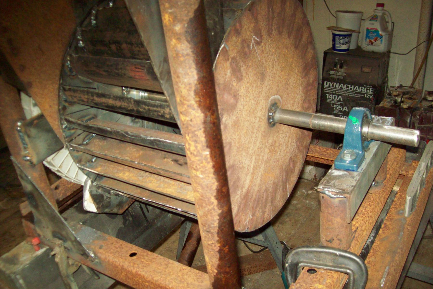
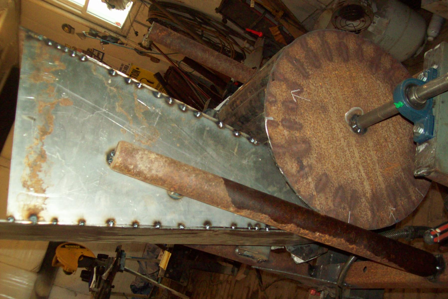
Garry these are designed for low head, I think I can get 3ft drop into the wheel. Running it with a drill it put out 3 phase, rectified to 35vdc@ 15amps. If it seems it can do more I can install another gen. on the flywheel pulley.
Nice work Al, I like your turbine! What are the dimensions that you used in terms of diameter, width, and vane size? Are the vanes cut from thin-walled tube? if so, what diameter was it? I am thinking of trying to build a new turbine to replace my squirrel cage fan, and this looks a lot like what I was envisioning. I remember finding a bunch of formulas to design an “ideal” crossflow turbine, but seem to recall that with my rather small flow rate, i got some weird dimensions. I have about 200 gpm (0.0126 m^3 / sec) coming down my pipeline, and i have a net head of 14’ (4.25 m).
My experience so far is that the intake for my penstock is the weakest link - but with only 3 feet of head, are you going to have to pipe your water far?
My feeling on the flywheel is that it might not really be needed, but it probably cant hurt. My guess is that the water will spin it up just fine, and then it will help keep a nice consistent output RPM.
I will also weigh in and say that batteries would probably be a much easier solution than trying to run an inverter directly. the speed your turbine is going to be spinning will depend on the load you place on the generator - it would be a nightmare to try and get it to regulate itself, and you dont want the whole thing to just stop if you apply a load that is larger than the max output it can handle.
Looking forward to seeing it up and running, keep up the good work!
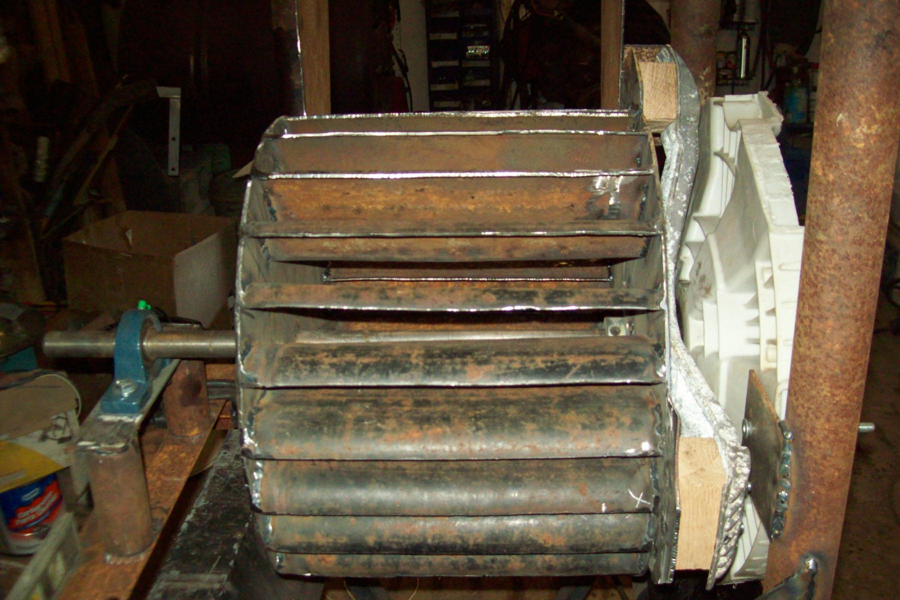
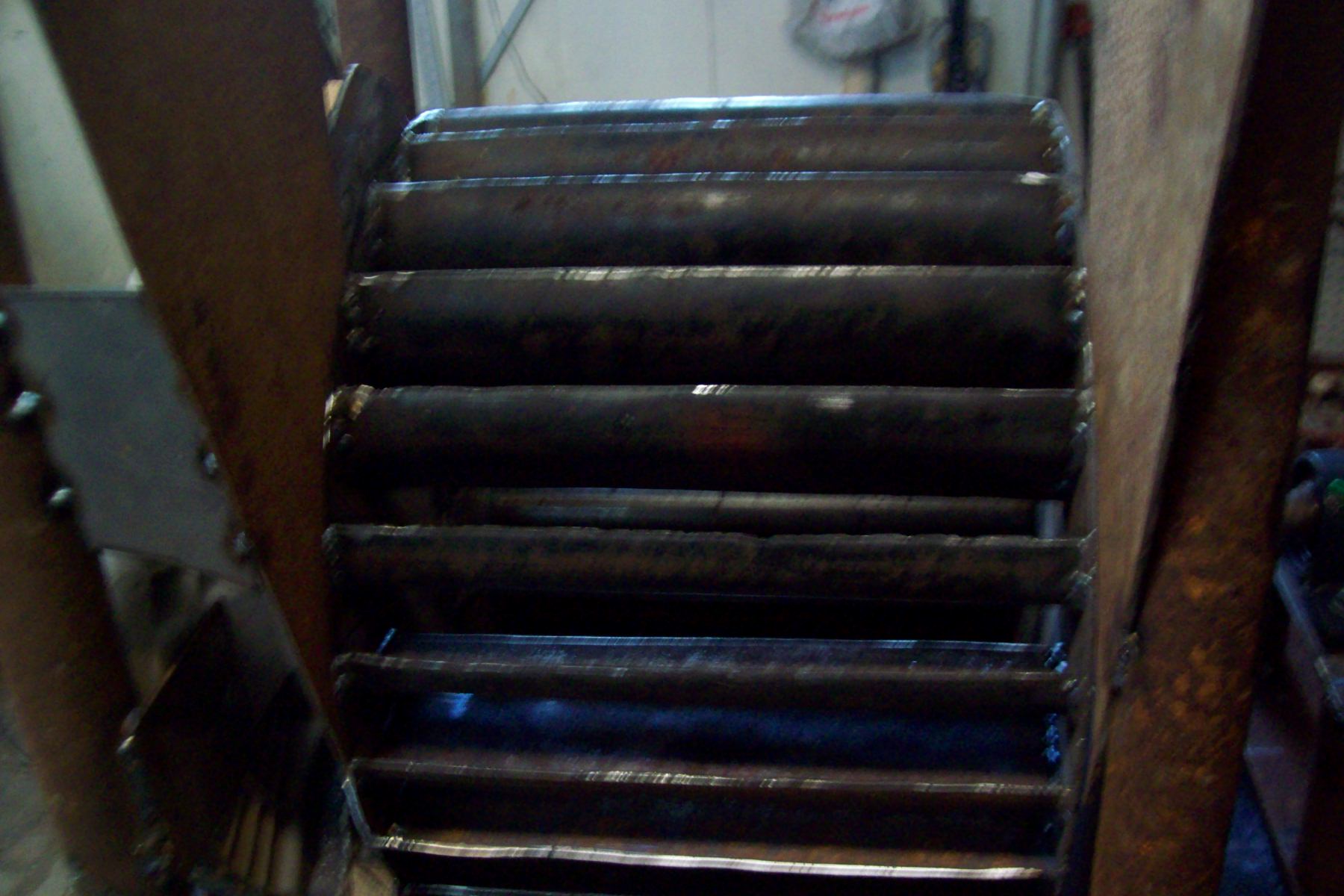
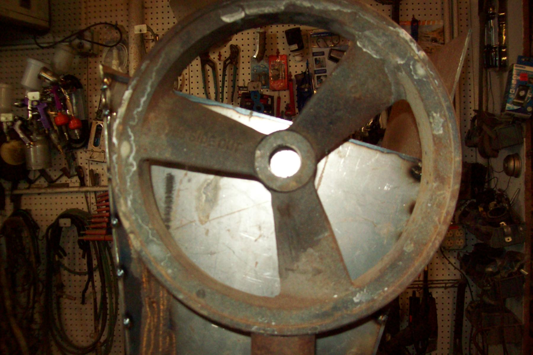
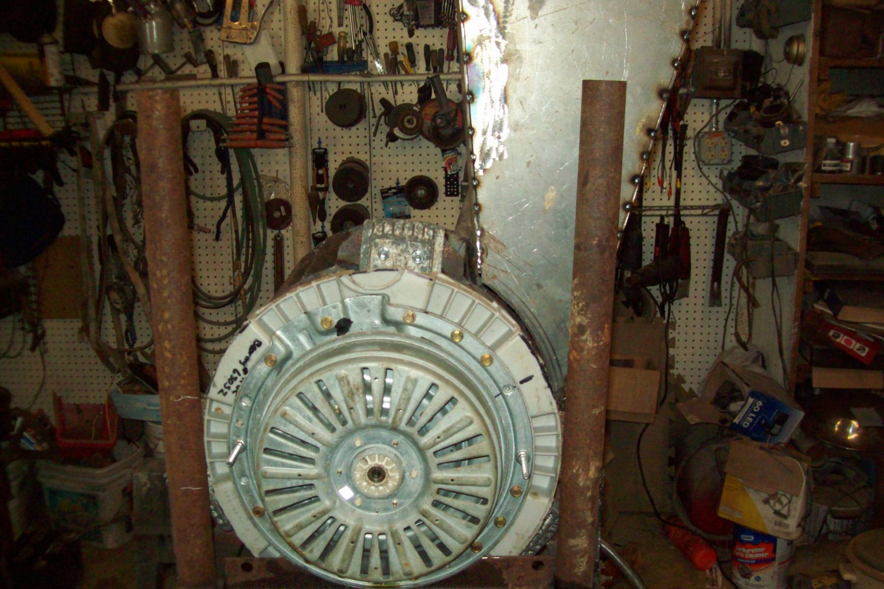
Carl, this is a total experiment, dim.; 16in dia, 12in wide, the vanes were cut from 2in pipe, cut in half. pressed, and hammered to the shape of an air plane wing sliced length wise. The stream I have has lots of flow, not much head. I’m going to channel as much water as possible through a flume, and drop it straight down to wheel. Here is good info.https://pdf.usaid.gov/pdf_docs/PNAAP285.pdf
Well I am looking forward to seeing how it turns out. There was some interesting stuff in that PDF. I revisited some of the plans I had looked at (found here: Crossflow Turbine - A DIY Design Manual | PDF | Circle | Turbine ) and I am going to attempt to put together something similar. I will post some pics when I get something starting to take shape. Keep us posted on your progress!
Hey Al, I got some good work done on my turbine today.
Here is a picture of the Mark II
I got a section of 3" thin walled stainless pipe that I cut up for my vanes, and then I used a a thick steel pipe section with a 3.5" outside diameter to hammer them into the ideal radius of curvature according to the equations in that design manual. There are 18 vanes in all, and it took a little doing to get the brazing to turn out right. Some of the vanes are not perfectly aligned, but I think it is going to work. I will install it tomorrow along with a bigger nozzle, and see if I can squeeze a few more watts out of my system.
Very nice. I would aim to cut the vane profile into the end plates. It could be tedious, not a bad job with a plasma cutter, but would allow simple assembly.
Getting the end plates cut with a plasma cutter at the local steel shop had been my first plan, but I got bogged down trying to make the CAD file. with a total of 36 grooves, and nothing but a little jig saw to make the cuts, i quickly gave up on trying to make them myself. The silver braze I used was really expensive, but once I got the hang of it, I only needed a tiny bit on each vane.
I am fairly confident that it is more or less balanced, at least for the sorts of speeds I am going to subject it to. I weighed my individual vanes and they deviated from the average by maybe 5% at most. The whole assembly probably weighs 10 pounds, so I am hoping that it will act a bit as a flywheel. I am going to slap it in this morning and see how it goes.
The good news was that swapping out the turbines was really easy - I managed to get the new one close enough to fit right in to my housing. Here is the Mark II next to the blower fan.
The bad news is that I didnt get as much of a bump in performance as I had hoped for. It was putting out 75watts or so, now it has maybe crept up to 85, with the occaisonal surge up to 95 watts. Its not nothing, and it lifts my daily output up closer to 2 kWh, so that is good. the water jet coming out the bottom now feels almost like it has more velocity to it, so I think the next step is to try out some larger pulleys and see if I can get some more juice that way. My ultimate goal is to get it up to 100 watts.
Here is the little bridge I finally got around to building, now looking at all the water flowing in the main creek, I get to thinking… what about a little undershot waterwheel? Maybe next year…
I understand that breast shot is about the highest efficiency. The Scots believed in “overshot” breast shot wheels, using a penstock similar to what a Banki turbine would have.
An undershot, backshot or breast shot wheel has the advantage in a stream that it will continue to rotate correctly if largely flooded.
You could greatly boost the power output of your current setup with more head.
Hey Garry, I skimmed over those PDF’s and they look interesting. I am going to file them away and hopefully not read them in depth until I am much more caught up on spring projects! I have 2 big design problems for making hydro work effectively at my place:
The water flow is highly variable. The water level in the main creek (flowing under my bridge) is about as high as it gets. Its probably about 10-12’ wide and a foot deep. In late summer, it will dry up to a trickle, to where I could channel the entire flow into a space 1 foot wide and less than a foot deep.
The terrain is pretty gradual. To get 14 feet of net head, I needed to run 400’ of pipe (losing several feet of head due to friction in the process). I could keep laying pipe back up the hill, but the slope doesnt get any better, it stays at about 5-7% all the way to the property line. I think I could run about 1200’ of penstock in all, but it would be a lot of work, and I would maybe have to think about larger pipe to reduce friction loss - which would be costly. Also, I would have to make sure that I designed a bulletproof intake, as walking half a mile to go clean the screen every day would be a chore.
I like how simple a waterwheel would be to build, so I imagine that I will probably try it at some point. I will keep you all posted!
I have a bigger creek to play with, but the same kinds of flow issues.
A tube penstock is a big project, and unless the diameter is very large, the friction losses will cancel the gain of head.
I would be looking more at making a stream bed dam upstream, and then take a wood or concrete flume to a generating site adjacent to the creek. That way in flooding the equipment is out of direct harm. Doubling or tripling the head of your present setup would be a great gain, and could be done with the same wheel.
I am sure you already know about the sectional Banki turbines, you could tack on a smaller section for very low flow conditions, and with greater head probably still generate significant power.