Hi Koen,
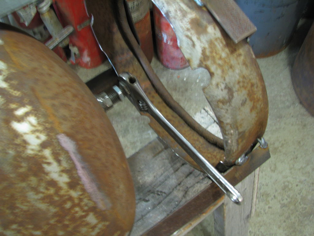
I have a horizontal rotatable grate with 2" sides and 1" or so less diam than the shell (housing). It sits on a 3/4" threaded rod run up through the bottom. I use a pr of vise grips to rotate it. (when I remember). With the threaded rod this grate is shaken back and forth through about 45 or 50 degrees. If you keep rotating mine in one direction it will move out of “adjustment” (imbert design dimensions on chart).
I haven’t seen a vertical shaker yet. I’m not sure I like the vertical movement for no particular reason though.
. The starter relay sounds like a good idea, but will it pull the fully loaded grate back to the starting point? I’m not sure if this is what you meant to use it for. A ratcheting system could work kicking it around x degrees per shot. A little more complex, I think. I’m doing the manual for now (see pics), but Dan Cox has a neat motor driven rotating grate, check out his posts here and his youtube vids, very informative, well thought out, diligently pursued and interestingly presented with some candid humor.
Pic 1 General build info
Pic 2 Wrench on welded on nut rotates grate
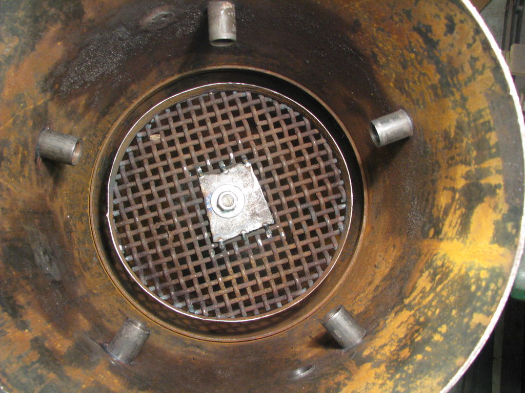
Pic 3 Size of grate, about 3/4" space around it. Attachment plate too large, see pic 4
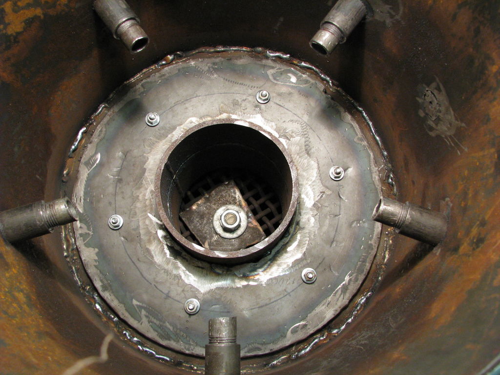
Pic 4 Hot gas flowing down through fire tube cannot use that portion of the glowing char above that large plate and a cool cone develops there and little or no reduction takes place there.Heat loss and less reduced gas equals lower quality gas. This is also my intro to internal leaks as I only spot welded the fire tube to its flange and gas was sucked around the tube by passing the reduction zone all together further reducing the quality of the gas. The flare had a lot of orange in it, compared to my present almost colorless gas.
Note also in Pic 4 that the firetube support flange is welded in and the firetube flange is gasketed and bolted to prevent gas by passing the reduction zone. Don’t skip this step, it’s a bear to tear down to do this after your gas doesn’t flare or burns smoky or has a moisture plume present in the flare.
The nozzles were 1/4’ holes drilled in plugs, not as shown.
Pic 5 I reduced the area affected by the support rod. Next time I will use four 1/4" x 3/4" x 5" arms welded to the rod to support the grate to further promote flow through the system. The new grate profile is supposed to help prevent clogging through better flow path.Exposes a lot of char edges to hot gas flow.. less prone to plugging than the small grid screen. Semi self clearing.
One more note, the grate height is adjustable for operating experimentation. I haven’t tried this yet. My gas is burning real clean so I’m not going to mess with this adjustment.
These are part of my 75% operator’s learning curve.
Hope this helps. Pepe
Matt, Thanks for the feed back on the timer, I’ll check it out. So far that gasket material seems to be working ok.